EP0125596A1 - Ruban d'isolation - Google Patents
Ruban d'isolation Download PDFInfo
- Publication number
- EP0125596A1 EP0125596A1 EP84105113A EP84105113A EP0125596A1 EP 0125596 A1 EP0125596 A1 EP 0125596A1 EP 84105113 A EP84105113 A EP 84105113A EP 84105113 A EP84105113 A EP 84105113A EP 0125596 A1 EP0125596 A1 EP 0125596A1
- Authority
- EP
- European Patent Office
- Prior art keywords
- insulating strip
- insulating
- cable
- end faces
- thickness
- Prior art date
- Legal status (The legal status is an assumption and is not a legal conclusion. Google has not performed a legal analysis and makes no representation as to the accuracy of the status listed.)
- Withdrawn
Links
- 239000000853 adhesive Substances 0.000 claims abstract description 7
- 230000001070 adhesive effect Effects 0.000 claims abstract description 7
- 239000010410 layer Substances 0.000 claims abstract description 5
- 230000001681 protective effect Effects 0.000 claims abstract description 5
- 239000012777 electrically insulating material Substances 0.000 claims abstract description 4
- 238000009413 insulation Methods 0.000 claims abstract description 4
- 239000012790 adhesive layer Substances 0.000 claims abstract description 3
- 230000001154 acute effect Effects 0.000 claims description 4
- 238000004804 winding Methods 0.000 abstract 1
- 101100390562 Mus musculus Fen1 gene Proteins 0.000 description 1
- 101100119953 Pyrococcus furiosus (strain ATCC 43587 / DSM 3638 / JCM 8422 / Vc1) fen gene Proteins 0.000 description 1
- 239000004020 conductor Substances 0.000 description 1
- 239000013013 elastic material Substances 0.000 description 1
Images
Classifications
-
- H—ELECTRICITY
- H02—GENERATION; CONVERSION OR DISTRIBUTION OF ELECTRIC POWER
- H02G—INSTALLATION OF ELECTRIC CABLES OR LINES, OR OF COMBINED OPTICAL AND ELECTRIC CABLES OR LINES
- H02G1/00—Methods or apparatus specially adapted for installing, maintaining, repairing or dismantling electric cables or lines
- H02G1/16—Methods or apparatus specially adapted for installing, maintaining, repairing or dismantling electric cables or lines for repairing insulation or armouring of cables
Definitions
- the invention relates to an insulating strip made of electrically insulating material with an adhesive layer on the inner surface for insulating uninsulated areas on strands, cables and the like. Like. By wrapping the insulating strip with the insulating strip.
- the invention has for its object to provide an insulating strip of the type mentioned, with which it is possible to easily and quickly isolate stripped points on cables and strands, especially in inaccessible places. Furthermore, two wires or strands knotted together should also be able to be connected to one another without any problems.
- the length and the thickness of the insulating strip correspond to the simple circumference or the thickness of the insulating layer of the strand or the cable, the end faces at the beginning and end of the insulating strip are cut obliquely and the inner surface of the insulating strip and the blunt Angled end face are covered with an adhesive on which there is a protective film.
- the insulating strips are adapted in length and thickness to the location to be isolated in just one turn around this point and firmly glued to the adjacent areas of the strand or the cable.
- the end faces at the beginning and end of the insulating strip are cut obliquely in such a way that these end faces fit against one another when the insulating strip is placed in one turn around the point to be insulated.
- the two end faces at the beginning and end of the insulating strip expediently run parallel to one another. This is particularly useful in cases in which the elasticity of the insulating strip is high and at the same time the thickness of the insulating strip is small compared to the diameter of the cable to be insulated.
- the end faces expediently run on Start and end of the insulating strip so that their imaginary extensions enclose an acute angle.
- the insulating strip is advantageously made of rubber. This gives the insulating strip a high degree of elasticity, so that any unevenness and irregularities in the cable to be insulated do not appear to be a further problem.
- the end faces are chamfered, they offer comparatively large connecting areas for the adhesive. In addition, any unevenness and tolerances in the cable can be adjusted. As a result, a sleeve is wrapped around the cable, which is used not only to isolate a damaged area, but which also mechanically holds the isolated area together.
- the width of the insulating strip can be kept approximately the same for the essential applications, while the length of the insulating strip must be adapted to the circumference of the cable to be insulated. This means that there must be correspondingly different fits for different cable diameters.
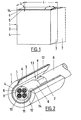
- the insulating strip shown in FIG. 1 (not to scale) fen 1 is made of electrically insulating material. Its length 1 corresponds to the circumference of the cable to be insulated, while its width b is adapted approximately to the thickness of the insulation layer of the cable.
- the end faces 2 and 3 at the beginning and end of the insulating strip 1 are cut obliquely.
- an adhesive 5 is provided, on which a protective film 6 is located.
- the end faces 2 and 3 can run parallel to one another, as is shown in solid lines in FIG. 1. In other cases, it is advisable to arrange the end face adjoining the inside 4 as shown in dashed lines in FIG. This also takes into account the difference between the inside diameter and the outside diameter of the insulating strip 1 when it is wound around a cable. In the embodiment shown in dashed lines in Figure 1, the end faces 2 and 7 at the beginning and end of the insulating strip 1 run such that their imaginary extensions enclose an acute angle.
- FIG. 2 shows the state in which the insulating strip 1 is partially wrapped around a cable 8 with the strands 9, 10, 11 and 12.
Landscapes
- Cable Accessories (AREA)
- Insulating Bodies (AREA)
Applications Claiming Priority (2)
| Application Number | Priority Date | Filing Date | Title |
|---|---|---|---|
| DE19838314164 DE8314164U1 (de) | 1983-05-13 | 1983-05-13 | Isolierstreifen |
| DE8314164U | 1983-05-13 |
Publications (1)
| Publication Number | Publication Date |
|---|---|
| EP0125596A1 true EP0125596A1 (fr) | 1984-11-21 |
Family
ID=6753306
Family Applications (1)
| Application Number | Title | Priority Date | Filing Date |
|---|---|---|---|
| EP84105113A Withdrawn EP0125596A1 (fr) | 1983-05-13 | 1984-05-07 | Ruban d'isolation |
Country Status (2)
| Country | Link |
|---|---|
| EP (1) | EP0125596A1 (fr) |
| DE (1) | DE8314164U1 (fr) |
Cited By (2)
| Publication number | Priority date | Publication date | Assignee | Title |
|---|---|---|---|---|
| CN113161936A (zh) * | 2021-04-14 | 2021-07-23 | 国网安徽省电力有限公司凤台县供电公司 | 一种卡扣机构以及绝缘包裹机器人 |
| CN114597828A (zh) * | 2022-05-01 | 2022-06-07 | 翁会兰 | 一种电缆用破损处修补装置及修补方法 |
Families Citing this family (1)
| Publication number | Priority date | Publication date | Assignee | Title |
|---|---|---|---|---|
| DE102012210455A1 (de) | 2012-06-21 | 2013-12-24 | Robert Bosch Gmbh | Verfahren zum Reparieren einer Zelle mit einem metallischen Gehäuse, die eine Beschädigung an einer elektrischen Isolationsschicht aufweist |
Citations (4)
| Publication number | Priority date | Publication date | Assignee | Title |
|---|---|---|---|---|
| DE1950021A1 (de) * | 1968-10-04 | 1970-04-09 | Hitachi Ltd | Kommutatorloser Motor |
| DE2937749A1 (de) * | 1979-09-18 | 1981-03-19 | Siemens AG, 1000 Berlin und 8000 München | Mehrfache wiederverwendbare kabelmuffe aus schrumpfbarem material |
| US4278836A (en) * | 1978-09-15 | 1981-07-14 | Bingham Loran S | Repair coupling for flexible electrical conduit |
| DE3115330A1 (de) * | 1980-04-24 | 1982-01-14 | Thomas & Betts Corp., 08869 Raritan, N.J. | Schutzhuelle fuer abgedichtete kabelspleissverbindungen |
-
1983
- 1983-05-13 DE DE19838314164 patent/DE8314164U1/de not_active Expired
-
1984
- 1984-05-07 EP EP84105113A patent/EP0125596A1/fr not_active Withdrawn
Patent Citations (4)
| Publication number | Priority date | Publication date | Assignee | Title |
|---|---|---|---|---|
| DE1950021A1 (de) * | 1968-10-04 | 1970-04-09 | Hitachi Ltd | Kommutatorloser Motor |
| US4278836A (en) * | 1978-09-15 | 1981-07-14 | Bingham Loran S | Repair coupling for flexible electrical conduit |
| DE2937749A1 (de) * | 1979-09-18 | 1981-03-19 | Siemens AG, 1000 Berlin und 8000 München | Mehrfache wiederverwendbare kabelmuffe aus schrumpfbarem material |
| DE3115330A1 (de) * | 1980-04-24 | 1982-01-14 | Thomas & Betts Corp., 08869 Raritan, N.J. | Schutzhuelle fuer abgedichtete kabelspleissverbindungen |
Cited By (2)
| Publication number | Priority date | Publication date | Assignee | Title |
|---|---|---|---|---|
| CN113161936A (zh) * | 2021-04-14 | 2021-07-23 | 国网安徽省电力有限公司凤台县供电公司 | 一种卡扣机构以及绝缘包裹机器人 |
| CN114597828A (zh) * | 2022-05-01 | 2022-06-07 | 翁会兰 | 一种电缆用破损处修补装置及修补方法 |
Also Published As
| Publication number | Publication date |
|---|---|
| DE8314164U1 (de) | 1983-09-29 |
Similar Documents
| Publication | Publication Date | Title |
|---|---|---|
| DE69323918T2 (de) | Elektrisches Kabel | |
| DE69607112T2 (de) | Verbindung von energiekabeln | |
| DE19549406C2 (de) | Verfahren zur Herstellung eines Sektorleiters für elektrische Energiekabel | |
| DE8111469U1 (de) | Schutzhülle für abgedichtete Kabelspleißverbindungen | |
| DE19857334A1 (de) | Kabelgarnitur zum Schutz einer Kabelverbindung in der Mittelspannungstechnik | |
| DE3522173C1 (de) | Geschirmte Bandleitung | |
| DE8018519U1 (de) | Wickelbare Kabelmuffeneinlage | |
| DE8314164U1 (de) | Isolierstreifen | |
| DE7709329U1 (de) | Geschirmtes, kunststoffisoliertes Starkstromkabel mit Schichtenmantel | |
| DE3131274C2 (de) | Erdverbindung für Schichtenmantel oder dgl. eines elektrischen Kabels | |
| DE1965224A1 (de) | Verfahren und Vorrichtung zum Herstellen von Paaren oder Vien von Fernsprechkabeln in einem Arbeitsgang | |
| DE2419843A1 (de) | Abgeschirmtes elektrisches kabel, das mindestens einen isolierten leiter und eine metallische abschirmung um denselben aufweist | |
| DE3016585A1 (de) | Mehrader-kabelverbindung fuer mittelspannungs-kabel | |
| DE2516041C2 (de) | Anordnung zur Erdverbindung eines Kabelschirms und Verfahren zur Herstellung | |
| DE2628151A1 (de) | Verfahren zum anbringen eines schutzkontaktes an einem kabel und schutzvorrichtung hierfuer | |
| DE69412810T2 (de) | Elektrisches kabel und sein herstellungsverfahren | |
| DE10231205A1 (de) | Verfahren zum Bewickeln von Transformatoren | |
| DE19522628C2 (de) | Verfahren zur Herstellung eines Sektorleiters für elektrische Energiekabel | |
| DE2537377C3 (de) | Anordnung zur Erdverbindung eines Kabelschirms | |
| DE2422003A1 (de) | Starkstromkabel mit extrudierter kunststoffisolierung und extrudierter leitender deckschicht | |
| DE547545C (de) | Hochspannungskabel mit schraubenfoermig angeordneten elektrostatischen Schutzbaendern | |
| DE3336195A1 (de) | Leitungsstueck einer elektrischen leitung | |
| DE29514144U1 (de) | Klemmverbindung zum Anschluß eines elektrischen Leiters an den Schirm und/oder den Metallmantel eines elektrischen Kabels | |
| DE950204C (de) | Gerillter rohrfoermiger Leiter, insbesondere fuer die UEbertragung von Hochfrequenzstroemen | |
| DE19522627A1 (de) | Verfahren zur Herstellung eines Leiters für elektrische Energiekabel |
Legal Events
| Date | Code | Title | Description |
|---|---|---|---|
| PUAI | Public reference made under article 153(3) epc to a published international application that has entered the european phase |
Free format text: ORIGINAL CODE: 0009012 |
|
| AK | Designated contracting states |
Designated state(s): BE DE FR GB IT NL SE |
|
| STAA | Information on the status of an ep patent application or granted ep patent |
Free format text: STATUS: THE APPLICATION IS DEEMED TO BE WITHDRAWN |
|
| 18D | Application deemed to be withdrawn |
Effective date: 19850722 |