EP0125635A2 - Méthode pour sélectionner un signal de réception composite dans les appareils d'inspection ultrasonore et appareil correspondant - Google Patents
Méthode pour sélectionner un signal de réception composite dans les appareils d'inspection ultrasonore et appareil correspondant Download PDFInfo
- Publication number
- EP0125635A2 EP0125635A2 EP84105289A EP84105289A EP0125635A2 EP 0125635 A2 EP0125635 A2 EP 0125635A2 EP 84105289 A EP84105289 A EP 84105289A EP 84105289 A EP84105289 A EP 84105289A EP 0125635 A2 EP0125635 A2 EP 0125635A2
- Authority
- EP
- European Patent Office
- Prior art keywords
- composite signal
- gate
- signal
- composite
- ultrasonic
- Prior art date
- Legal status (The legal status is an assumption and is not a legal conclusion. Google has not performed a legal analysis and makes no representation as to the accuracy of the status listed.)
- Granted
Links
Images





Classifications
-
- G—PHYSICS
- G01—MEASURING; TESTING
- G01N—INVESTIGATING OR ANALYSING MATERIALS BY DETERMINING THEIR CHEMICAL OR PHYSICAL PROPERTIES
- G01N29/00—Investigating or analysing materials by the use of ultrasonic, sonic or infrasonic waves; Visualisation of the interior of objects by transmitting ultrasonic or sonic waves through the object
- G01N29/36—Detecting the response signal, e.g. electronic circuits specially adapted therefor
- G01N29/38—Detecting the response signal, e.g. electronic circuits specially adapted therefor by time filtering, e.g. using time gates
-
- G—PHYSICS
- G01—MEASURING; TESTING
- G01N—INVESTIGATING OR ANALYSING MATERIALS BY DETERMINING THEIR CHEMICAL OR PHYSICAL PROPERTIES
- G01N29/00—Investigating or analysing materials by the use of ultrasonic, sonic or infrasonic waves; Visualisation of the interior of objects by transmitting ultrasonic or sonic waves through the object
- G01N29/04—Analysing solids
- G01N29/07—Analysing solids by measuring propagation velocity or propagation time of acoustic waves
-
- G—PHYSICS
- G01—MEASURING; TESTING
- G01N—INVESTIGATING OR ANALYSING MATERIALS BY DETERMINING THEIR CHEMICAL OR PHYSICAL PROPERTIES
- G01N29/00—Investigating or analysing materials by the use of ultrasonic, sonic or infrasonic waves; Visualisation of the interior of objects by transmitting ultrasonic or sonic waves through the object
- G01N29/44—Processing the detected response signal, e.g. electronic circuits specially adapted therefor
- G01N29/48—Processing the detected response signal, e.g. electronic circuits specially adapted therefor by amplitude comparison
-
- G—PHYSICS
- G01—MEASURING; TESTING
- G01N—INVESTIGATING OR ANALYSING MATERIALS BY DETERMINING THEIR CHEMICAL OR PHYSICAL PROPERTIES
- G01N2291/00—Indexing codes associated with group G01N29/00
- G01N2291/01—Indexing codes associated with the measuring variable
- G01N2291/015—Attenuation, scattering
-
- G—PHYSICS
- G01—MEASURING; TESTING
- G01N—INVESTIGATING OR ANALYSING MATERIALS BY DETERMINING THEIR CHEMICAL OR PHYSICAL PROPERTIES
- G01N2291/00—Indexing codes associated with group G01N29/00
- G01N2291/02—Indexing codes associated with the analysed material
- G01N2291/028—Material parameters
- G01N2291/02854—Length, thickness
-
- G—PHYSICS
- G01—MEASURING; TESTING
- G01N—INVESTIGATING OR ANALYSING MATERIALS BY DETERMINING THEIR CHEMICAL OR PHYSICAL PROPERTIES
- G01N2291/00—Indexing codes associated with group G01N29/00
- G01N2291/04—Wave modes and trajectories
- G01N2291/044—Internal reflections (echoes), e.g. on walls or defects
Definitions
- the present invention relates to an ultrasonic flaw detecting technique and particularly includes a technique in which ultrasonic waves are generated from a plurality of vibrator elements with delay time factors, the reflection echoes of the ultrasonic waves are received, the received signals are composed with the delay time factors, and judgement is made as to whether the composite signal is a composite signal based on the reception signals from the focal area in the main lobe or not.
- An ultrasonic inspection apparatus for inspecting the inside of an object to be inspected or a test piece by using a plurality of ultrasonic vibrator elements is known, for example, by U.S. Patent No. 4,173,007 and Japanese Patent Application Laid-open No. 211061/1982.
- the ultrasonic wave transmission timings of the respective vibrator elements are controlled through delay means so that it is made possible to attain a state in which the acoustic pressure distribution of the acoustic waves transmitted from the vibrator elements toward the test piece is collected or focused onto the inspection target position and to perform the scanning to displace the focal point.
- a probe composed of a plurality of ultrasonic vibrator elements is called an array probe or array sensor. Combining this array probe with delay means, as described above, it is made possible to higher the acoustic pressure at the inspection target position to increase the intensity of the reflection echo from the inspection target position.
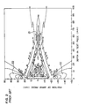
- Fig. 4 shows the state of acoustic pressure level in the test piece 10 when the same first delay time is given to each of the vibrator elements 3A and 3B, a second delay time which is slightly delayed from the first one is given to the vibrator element 3C, and a third delay time which is slightly delayed from the second delay time is given to the vibrator element 3D.
- a pseudo focal point F' can be formed in addition to the desired focal point F.
- the ultrasonic waves are superposed in the state that the wavelengths of the respective waves are shifted by integer multiple to form a portion of high acoustic pressure level, resulting in the formation of grating lobe.
- An object of the present invention is therefore to provide a method of transmitting/receiving ultrasonic waves and an apparatus therefor.
- the ultrasonic inspection method in which ultrasonic waves respectively transmitted from a plurality of vibrator means are reflected by a reflector in a test piece to produce reflection waves and the reflection waves are received as reception signals which are composed into a composite signal, comprises the steps of: detecting the existence of a composite signal based on the reflection waves from a focal point in a main lobe at each of at least a first time point at which the composite signal can be detected, a second and a third time point in the vicinity of the first time point at which the composite signal can not be detected; and deciding that the composite signal is based on the reflection waves from a position of inspection target when the existence of the composite signal is detected only at the first time point.
- the ultrasonic inspection apparatus comprising a plurality of vibrator means, composing means for receiving respective output signals of the plurality of vibrator means to compose the output signals to thereby produce an output
- signal processing means for receiving the output of the composite means
- a time gate circuit including: a plurality of detection means which are arranged to receive the output of the composite means and detecting operation time points of which are set to a time point at which a composite signal based on the reflection waves from a focal point in a main lobe can be detected and a time point at which the composite signal can not be detected; and a judgement circuit connected to the respective outputs of the plurality of detection means and for judging a state in which a part of the plurality of detection means detect the composite signal while the remainder of the plurality of detection means can not detect the composite signal.
- Figs. 5, 6, 7a, 7b and 7c are diagrams for the explanation of the principle.
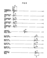
- Fig. 5 shows that in what timing the ultrasonic waves are transmitted from the vibrator elements 3A to 3D of Fig. 4 and in what timing the ultrasonic echoes with respect to the transmitted ultrasonic waves are received from the focal point F when a reflector exists at the focal point F.
- the ultrasonic waveform transmitted from each of the vibrator elements 3A to 3D is the fundamental transmission wave A as shown if a high tension impulse is directly applied to each vibrator element, a high tension impulse is applied to the respective vibrator elements through the corresponding delay elements in an actual case so that the impulse is transmitted as the transmission waves A 1 , A 2 , A3 and A4 from the respective vibrator elements.
- the transmission timings from the respective vibrator elements 3A to 3D are shifted in the manner as shown in Figs. 5 and 11.
- the transmission timings are adjusted by the respective delay elements such that the transmission waves A 1 , A 2 , A3 and A4 can reach the focal point F at the same time and the respective phases of the transmission waves A 1 , A 2 , A 3 and A4 coincide with each other, so that the composite wave B of the transmission waves A l , A 2 , A 3 and A4 is as shown in Fig. 5. If a reflector exists at the focal point F, the composite wave B of the transmission waves A 1 , A 2 , A3 and A4 is reflected as reflection echoes toward the respective vibrator elements with the same phase and the same timing.
- the vibrator elements 3A to 3D receive this reflection echoes as the reception waves B 1 , B 2 , B 3 and B 4 after the lapse of time corresponding to the wave propagation distances from the focal point F to the respective vibrator elements 3A to 3D, so that the reception timings of the reception waves B 1 , B 2 , B 3 and B 4 become shifted from each other, as shown in Figs. 5 and 11, by the time difference set in the respective delay elements.
- the reception waves B l , B 2 , B 3 and B 4 are converted by the respective vibrator elements 3A to 3D into electric signals which are passed through the respective delay elements to make the above-mentioned time difference vanish and added to each other to be composed into a reception composite wave C.
- the arrival timings of the respective transmission waves Al, A 2 , A3 and A4 coincide with each other, so that the duration of the composite signal B is the same as the duration G of the fundamental transmission wave A.
- the duration of each of the reception waves B 1 , B 2 , B 3 and B 4 also coincides with the duration of the fundamental transmission wave A. If such reception waves B 1 , B 2' B 3 and B 4 are added to be composed with each other while they are registered with each other in timing at their respective left end in the drawing, the duration of the composite reception wave C obtained by the above-mentioned addition and composition substantially coincides with the duration G of the fundamental transmission wave A.
- Figs. 6 and 12 similarly shows the various waveforms shown in Figs. 5 and 11, with respect to the pseudo focal point F'.
- the duration of the composite wave D at the pseudo focal point F ' of the respective transmission waves All A 2 , A3 and A4 is longer than the duration G of the fundamental transmission wave A. This is because the transmission ultrasonic wave from the vibrator element 3D first apears at the pseudo focal point F' and then the transmission ultrasonic waves from the vibrator elements 3C, 3B, and 3A successively appear at the pseudo focal point F' in above-named order, to thereby be composed thereat.
- ultrasonic echoes are reflected from a reflector toward the vibrator elements 3A to 3D if the reflector exists at the pseudo focal point F', the reflection timings do not coincide with each other and shift by integer multiple from each other differing from the case of Fig. 5.
- the ultrasonic echoes reflected from the pseudo focal point F' and received by the vibrator elements 3A to 3D as the reception waves B l ,, B 2 , B 3 and B 4 are as shown in Fig. 6 and the duration of the addition/composite wave E is further elongated.
- a focal point F is determined in advance as a detection position, the respective timings at which the ultrasonic echoes are received by the vibrator elements are known at the time when the focal point is determined and the duration of the ultrasonic echoes are also known, so that if this fact is utilized, it is made possible to judge or determine whether the ultrasonic echoes are based on the main lobe or grating lobe when the ultrasonic echoes are obtained.
- Figs. 7a, 7b, and 7c illustrate the way of judgement.
- the duration of the composite reception wave C with respect to the focal point F is substantially the same as that of the transmission ultrasonic wave and therefore it is made possible to perform the judgement as to whether the ultrasonic echoes are those from the main lobe of ultrasonic beam or not on the basis of an ultrasonic signal extracted though a time gate having time width agreed with the period of the used ultrasonic wave.
- a delay circuit control signal used in an ultrasonic beam control device (32 in Fig. 8).
- the ultrasonic beam control device (32) performs the setting of the amount of delay time of a delay circuit (34 in Fig.
- TTL level of a transistor-transistor-logic (TTL) (not shown) used is a circuit in which the TTL level signal (delay circuit control signal) is converted into an analog quantity of voltage by a D-A converter and a gate is opened when a comparator detects the fact that the analog quantity of voltage exceeds a predetermined voltage.
- TTL level signal delay circuit control signal
- a gate is opened when a comparator detects the fact that the analog quantity of voltage exceeds a predetermined voltage.
- the gate starting time is set such that one of the three time gates abstracts the ultrasonic echoes from the focal point F, one of the remainder two time gates extracts the ultrasonic echoes reflected before the first-mentioned ultrasonic echoes, and the remainder time gate starts its time gating at the ending time of the duration of the ultrasonic echoes from the focal point F.
- the ultrasonic reception signals extracted through these at least three time gates a, b and c which are the gate outputs a 0 , b 0 and c 0 are converted through waveform shapers such as comparators into digital.
- each of the digital signals a l , b 1 and c 1 can take, generally, either one of the two states, "0" and “1"
- the operations may include eight modes as shown in the following table.
- Fig. 8 shows the outline of arrangement of the apparatus.
- an input device 31 serves to input control parameters such as the acoustic velocity in the test piece, the frequency of the used ultrasonic wave, the scanning region of the ultrasonic beam in the test piece, etc. which are applied to an ultrasonic beam control device 32.
- the ultrasonic beam control device 32 performs its control operation such that it transmits a pulse generation signal, a delay time control signal, a time gate start signal (including a time gate width signal), and flaw position signal to a pulse generator 33, a delay circuit 34, a time gate circuit 36, and a signal processing device 37, respectively, so that an ultrasonic beam is transmitted to a predetermined position in a test piece and an obtained reflection echo signal is displayed.
- the pulse generator 33 generates a high tension pulse (impulse or high-frequency pulse) for ultrasonic inspection in response to the pulse generation signal from the ultrasonic beam control device 32 and transmits the high tension pulse to the delay circuit 34.
- the delay circuit 34 supplies the high tension pulse from the pulse generator 33 to an array probe with time delays in response to the delay time control signal for vibrator elements of the array probe 35 from the ultrasonic beam control device 32.
- the array probe 35 transmits, on the basis of the time-delayed high tension pulses, ultrasonic beams under the control of deflection and focusing into a test piece.
- the thus transmitted ultrasonic waves propagates in the test piece and reflected by a reflector if there exists any reflector in the test piece.
- the reflection ultrasonic waves are received by the array probe 35 and then supplied to a signal processing device 37 and a gate circuit 36 according to the present invention after composed through the delay circuit 34.
- time gate circuit 36 a necessary portion is extracted out of the reception ultrasonic waves in response to the time gate start signal and the time gate width signal from the ultrasonic beam control device 32 and the extracted ultrasonic signal portion is subject to logic operations in a predetermined way after it has been coded into a binary signal of "0" and "1" by a waveform shaper in the circuit 36, the result of logic operations being supplied to the signal processing device 37.
- the signal processing device 37 Upon the reception of the result of logic operations, the signal processing device 37 obtains the position of the reflector by using an ultrasonic beam control signal, with respect to the incident angle of ultrasonic beam into the test piece, the focal position in the test piece, etc., applied from the ultrasonic beam control device 32, a reception ultrasonic signal from the delay circuit 34, and an reflection wave judgement signal representing the reflection ultrasonic wave from the main lobe of ultrasonic beam applied from the time gate circuit 36.
- the signal processing device 37 transmits data such as a reflector position signal, an ultrasonic scanning signal, etc., to the display 38.
- the display 38 can display the shape of the reflector in the test piece on A, B and C scopes, the indication as to whether the reflection waves are those from the main lobe of the ultrasonic beam or not, or only the indication of the reflection waves from the main lobe.
- Fig. 9 is a time chart of various signals in the circuit 36.
- the three gate circuits Upon the reception of a gate width signal H from the ultrasonic beam control device 32, the three gate circuits set their gate widths respectively corresponding to the gate width signal and wait for the respective gate start signals a 0 ', b 0 ' and c 0 '. That is, the time (gate width) of the three gates 51a, 51b, and 51c is set on the basis of the gate width signal and the time gates 51a, 51b, and 51c wait for the gate start signals a 0 ', b O t and c 0 '.
- the gate width signal H is inputted in advance into the input device 31 as one wavelength time of ultrasonic wave. Since the gate start time varies depending on the kind of used array probe, the gate start time is once inputted into the input device 31 and made agreed with the reception of ultrasonic wave by using a computing circuit or computer in the ultrasonic beam control device 32 to thereby transmit the signals a 0 ', b 0 ' and c 0 '.
- the composite signal C is subject to the time gates a, b and c so that the composite signal portions are extracted at the respective time gates a, b and c as the gate outputs a 0 , b 0 and c Q .
- These gate outputs a 0 , b 0 and c 0 are converted into the digital signals a 1 , b 1 and c 1 of "0" and "1" which are outputted and held as they are until the gate time band of the time gate c terminates.
- Fig. 9 is a time chart in the case where the ultrasonic echoes are those from the main lobe of the ultrasonic beam.
- the gate circuits 51a, 51b and 51c corresponding to the time gates a, b and c are supplied with a common composite reception wave as well as the corresponding gate start signals a 0 ', b 0 ' and c 0 '.
- the respective gate outputs a 0 , b 0 and c 0 from the gate circuits 51a, 51b and 51c are converted into the digital signals a l , b 1 and c l through waveform shaping circuits 52a, 52b, and 52c, which are constituted by such as comparators having variable sensitivity-adjusting-threshold value so as to have flip-flop functions, and then processed to gain a logical product by an AND circuit 54 in response to the gate start signal c 0 '.
- Invertors 53a and 53c are provided for inverting the digital signals a l and c l .
- the existence of ultrasonic echoes is detected at a time point at which ultrasonic echoes can be obtained and time points in advance of and in the behind of the first mentioned time point, and when the existence is detected in a predetermined manner, the ultrasonic echoes are received as those from the main lobe.
- the operations can be easily achieved, the arrangement is simple, and the position evaluation of a reflector existing in a test piece can be surely attained with a good S/N without being affected by the grating lobe.
Landscapes
- Physics & Mathematics (AREA)
- Health & Medical Sciences (AREA)
- Life Sciences & Earth Sciences (AREA)
- Chemical & Material Sciences (AREA)
- Analytical Chemistry (AREA)
- Biochemistry (AREA)
- General Health & Medical Sciences (AREA)
- General Physics & Mathematics (AREA)
- Immunology (AREA)
- Pathology (AREA)
- Engineering & Computer Science (AREA)
- Signal Processing (AREA)
- Acoustics & Sound (AREA)
- Investigating Or Analyzing Materials By The Use Of Ultrasonic Waves (AREA)
- Measurement Of Velocity Or Position Using Acoustic Or Ultrasonic Waves (AREA)
Applications Claiming Priority (2)
| Application Number | Priority Date | Filing Date | Title |
|---|---|---|---|
| JP58081797A JPS59208457A (ja) | 1983-05-12 | 1983-05-12 | 超音波送受信方法とその装置 |
| JP81797/83 | 1983-05-12 |
Publications (3)
| Publication Number | Publication Date |
|---|---|
| EP0125635A2 true EP0125635A2 (fr) | 1984-11-21 |
| EP0125635A3 EP0125635A3 (en) | 1988-05-04 |
| EP0125635B1 EP0125635B1 (fr) | 1990-12-19 |
Family
ID=13756476
Family Applications (1)
| Application Number | Title | Priority Date | Filing Date |
|---|---|---|---|
| EP84105289A Expired EP0125635B1 (fr) | 1983-05-12 | 1984-05-10 | Méthode pour sélectionner un signal de réception composite dans les appareils d'inspection ultrasonore et appareil correspondant |
Country Status (4)
| Country | Link |
|---|---|
| US (1) | US4592237A (fr) |
| EP (1) | EP0125635B1 (fr) |
| JP (1) | JPS59208457A (fr) |
| DE (1) | DE3483752D1 (fr) |
Cited By (2)
| Publication number | Priority date | Publication date | Assignee | Title |
|---|---|---|---|---|
| EP0211427A3 (fr) * | 1985-08-05 | 1989-08-02 | Hitachi, Ltd. | Appareil et méthode pour émettre et recevoir des signaux ultrasonores |
| KR100795822B1 (ko) * | 2006-03-24 | 2008-01-17 | 남종현 | 고지혈증 및 뇌졸중 회복 및 예방에 효과가 있는 천연 식물추출물 조성물, 이를 유효성분으로 하는 천연차 및 이의제조방법 |
Families Citing this family (14)
| Publication number | Priority date | Publication date | Assignee | Title |
|---|---|---|---|---|
| DE3788757D1 (de) * | 1986-08-20 | 1994-02-24 | Siemens Ag | Verfahren und Einrichtung zur adaptiven Fokussierung bei einem medizinischen Ultraschall-Bildgabegerät. |
| US5570691A (en) * | 1994-08-05 | 1996-11-05 | Acuson Corporation | Method and apparatus for real-time, concurrent adaptive focusing in an ultrasound beamformer imaging system |
| US6247367B1 (en) * | 1998-04-16 | 2001-06-19 | California Institute Of Technology | Multiplexed ultrasonic system |
| US6678403B1 (en) * | 2000-09-13 | 2004-01-13 | Peter J. Wilk | Method and apparatus for investigating integrity of structural member |
| DE10334902B3 (de) * | 2003-07-29 | 2004-12-09 | Nutronik Gmbh | Verfahren und Schaltungsanordnung zur Verarbeitung von Signalen, die bei der zerstörungsfreien Prüfung von Gegenständen durch Reflexion von Ultraschallwellen erzeugt werden |
| US8087297B2 (en) * | 2004-03-04 | 2012-01-03 | Ludwiczak Damian R | Vibrating debris remover |
| US7454973B2 (en) * | 2005-04-01 | 2008-11-25 | Hitachi, Ltd. | Ultrasonic inspection method and ultrasonic inspection equipment |
| US7467052B2 (en) * | 2005-11-10 | 2008-12-16 | Vaccaro Christopher M | Systems and methods for detecting discontinuous fibers in composite laminates |
| CN102970937B (zh) * | 2010-06-30 | 2015-07-08 | 富士胶片株式会社 | 超声诊断装置和超声诊断方法 |
| JP5798117B2 (ja) * | 2010-06-30 | 2015-10-21 | 富士フイルム株式会社 | 超音波診断装置及び超音波診断装置の作動方法 |
| US9595092B2 (en) * | 2013-05-10 | 2017-03-14 | The Boeing Company | Methods and systems for inspection of composite irregularities |
| JP6223783B2 (ja) * | 2013-11-07 | 2017-11-01 | 三菱日立パワーシステムズ株式会社 | 超音波探傷センサおよび超音波探傷方法 |
| US10018113B2 (en) * | 2015-11-11 | 2018-07-10 | General Electric Company | Ultrasonic cleaning system and method |
| US12153019B2 (en) * | 2021-03-31 | 2024-11-26 | Evident Scientific, Inc. | Adaptive total focusing method (TFM) such as for zero-degree acoustic inspection |
Family Cites Families (5)
| Publication number | Priority date | Publication date | Assignee | Title |
|---|---|---|---|---|
| DE2107063C3 (de) * | 1971-02-15 | 1979-08-23 | Krautkraemer, Gmbh, 5000 Koeln | Ultraschall-Impulsechoverfahren zur selbsttätigen Unterscheidung zwischen Nutz- und Störsignalen bei der zerstörungsfreien Werkstoffprüfung sowie Schaltungseinrichtung zur Durchführung des Verfahrens |
| US4267584A (en) * | 1977-07-01 | 1981-05-12 | Siemens Gammasonics, Inc. | Permutating analog shift register variable delay system |
| US4173007A (en) * | 1977-07-01 | 1979-10-30 | G. D. Searle & Co. | Dynamically variable electronic delay lines for real time ultrasonic imaging systems |
| US4228686A (en) * | 1978-01-03 | 1980-10-21 | Raytheon Company | Fresnel focussed imaging system |
| JPS5618854A (en) * | 1979-07-25 | 1981-02-23 | Fujitsu Ltd | Ultrasonic diagnosing device |
-
1983
- 1983-05-12 JP JP58081797A patent/JPS59208457A/ja active Granted
-
1984
- 1984-05-10 DE DE8484105289T patent/DE3483752D1/de not_active Expired - Lifetime
- 1984-05-10 EP EP84105289A patent/EP0125635B1/fr not_active Expired
- 1984-05-14 US US06/609,834 patent/US4592237A/en not_active Expired - Fee Related
Cited By (2)
| Publication number | Priority date | Publication date | Assignee | Title |
|---|---|---|---|---|
| EP0211427A3 (fr) * | 1985-08-05 | 1989-08-02 | Hitachi, Ltd. | Appareil et méthode pour émettre et recevoir des signaux ultrasonores |
| KR100795822B1 (ko) * | 2006-03-24 | 2008-01-17 | 남종현 | 고지혈증 및 뇌졸중 회복 및 예방에 효과가 있는 천연 식물추출물 조성물, 이를 유효성분으로 하는 천연차 및 이의제조방법 |
Also Published As
| Publication number | Publication date |
|---|---|
| JPH0257268B2 (fr) | 1990-12-04 |
| EP0125635A3 (en) | 1988-05-04 |
| US4592237A (en) | 1986-06-03 |
| JPS59208457A (ja) | 1984-11-26 |
| EP0125635B1 (fr) | 1990-12-19 |
| DE3483752D1 (de) | 1991-01-31 |
Similar Documents
| Publication | Publication Date | Title |
|---|---|---|
| US4592237A (en) | Method of selecting composite reception signal in ultrasonic inspection apparatus and apparatus therefor | |
| US3911730A (en) | Ultrasonic transducer probe system | |
| US4830015A (en) | Method and system for measuring an ultrasound tissue characterization | |
| JPH08103444A (ja) | 超音波診断装置及び超音波多重走査線ビーム形成方法 | |
| US4446740A (en) | Frequency controlled hybrid ultrasonic imaging arrays | |
| US4862892A (en) | Ultrasonic reflex transmission imaging method and apparatus with artifact removal | |
| CA1103489A (fr) | Appareil de type digital pour la reproduction holographie aux ultrasons | |
| WO2005012941B1 (fr) | Procede et circuit de controle non destructif d'objets au moyen d'ondes ultrasonores | |
| JPH08201356A (ja) | 固体材料の音速測定方法および超音波探触子 | |
| JP2763155B2 (ja) | 運動する器官や血液の運動速度を超音波エコーグラフで測定する装置 | |
| US5024094A (en) | Ultrasonic imaging system of bonding zone | |
| JP3709308B2 (ja) | 超音波振動方向制御方法及び装置並びに当該装置を用いた材料劣化診断装置 | |
| EP0068052B1 (fr) | Appareil et procédé pour l'imagerie ultrasonore | |
| US4361042A (en) | Digital type ultrasonic holography apparatus | |
| JP2507467B2 (ja) | 斜角超音波探傷装置 | |
| JP2001255308A (ja) | 超音波探傷方法及びその装置 | |
| SU864115A1 (ru) | Способ ультразвукового контрол листового проката | |
| EP0018079A1 (fr) | Appareil digital d'holographie à ultrason | |
| JP2803308B2 (ja) | 超音波診断装置 | |
| JPH08327613A (ja) | 電子走査型超音波検査方法及び装置 | |
| RU96100813A (ru) | Способ ультразвуковой дефектоскопии и устройство, его реализующее | |
| JPH0161181B2 (fr) | ||
| SU947747A2 (ru) | Ультразвуковой эхо-импульсный дефектоскоп | |
| JP6145202B1 (ja) | 超音波診断装置 | |
| JPH03114452A (ja) | 超音波診断装置 |
Legal Events
| Date | Code | Title | Description |
|---|---|---|---|
| PUAI | Public reference made under article 153(3) epc to a published international application that has entered the european phase |
Free format text: ORIGINAL CODE: 0009012 |
|
| AK | Designated contracting states |
Designated state(s): DE FR |
|
| PUAL | Search report despatched |
Free format text: ORIGINAL CODE: 0009013 |
|
| AK | Designated contracting states |
Kind code of ref document: A3 Designated state(s): DE FR |
|
| 17P | Request for examination filed |
Effective date: 19880506 |
|
| 17Q | First examination report despatched |
Effective date: 19891016 |
|
| GRAA | (expected) grant |
Free format text: ORIGINAL CODE: 0009210 |
|
| AK | Designated contracting states |
Kind code of ref document: B1 Designated state(s): DE FR |
|
| REF | Corresponds to: |
Ref document number: 3483752 Country of ref document: DE Date of ref document: 19910131 |
|
| ET | Fr: translation filed | ||
| PGFP | Annual fee paid to national office [announced via postgrant information from national office to epo] |
Ref country code: FR Payment date: 19910418 Year of fee payment: 8 |
|
| PGFP | Annual fee paid to national office [announced via postgrant information from national office to epo] |
Ref country code: LU Payment date: 19910826 Year of fee payment: 9 |
|
| PLBE | No opposition filed within time limit |
Free format text: ORIGINAL CODE: 0009261 |
|
| STAA | Information on the status of an ep patent application or granted ep patent |
Free format text: STATUS: NO OPPOSITION FILED WITHIN TIME LIMIT |
|
| 26N | No opposition filed | ||
| EPTA | Lu: last paid annual fee | ||
| PG25 | Lapsed in a contracting state [announced via postgrant information from national office to epo] |
Ref country code: FR Effective date: 19930129 |
|
| REG | Reference to a national code |
Ref country code: FR Ref legal event code: ST |
|
| PGFP | Annual fee paid to national office [announced via postgrant information from national office to epo] |
Ref country code: DE Payment date: 19960628 Year of fee payment: 13 |
|
| PG25 | Lapsed in a contracting state [announced via postgrant information from national office to epo] |
Ref country code: DE Free format text: LAPSE BECAUSE OF NON-PAYMENT OF DUE FEES Effective date: 19980203 |