EP0125643B1 - Abflusskanal, insbesondere Abflussrinne oder Abflussrohr - Google Patents
Abflusskanal, insbesondere Abflussrinne oder Abflussrohr Download PDFInfo
- Publication number
- EP0125643B1 EP0125643B1 EP84105308A EP84105308A EP0125643B1 EP 0125643 B1 EP0125643 B1 EP 0125643B1 EP 84105308 A EP84105308 A EP 84105308A EP 84105308 A EP84105308 A EP 84105308A EP 0125643 B1 EP0125643 B1 EP 0125643B1
- Authority
- EP
- European Patent Office
- Prior art keywords
- spray nozzles
- channel
- drain
- duct
- flushing
- Prior art date
- Legal status (The legal status is an assumption and is not a legal conclusion. Google has not performed a legal analysis and makes no representation as to the accuracy of the status listed.)
- Expired
Links
- 239000007921 spray Substances 0.000 claims description 30
- 238000004140 cleaning Methods 0.000 claims description 18
- 238000011010 flushing procedure Methods 0.000 claims description 15
- 239000003795 chemical substances by application Substances 0.000 claims description 4
- 239000002991 molded plastic Substances 0.000 claims 1
- 239000007787 solid Substances 0.000 description 7
- 239000011324 bead Substances 0.000 description 3
- 239000003599 detergent Substances 0.000 description 3
- 238000002347 injection Methods 0.000 description 2
- 239000007924 injection Substances 0.000 description 2
- 239000007788 liquid Substances 0.000 description 2
- 239000000463 material Substances 0.000 description 2
- 150000001875 compounds Chemical class 0.000 description 1
- 238000004519 manufacturing process Methods 0.000 description 1
- 238000002360 preparation method Methods 0.000 description 1
- 238000009420 retrofitting Methods 0.000 description 1
- XLYOFNOQVPJJNP-UHFFFAOYSA-N water Substances O XLYOFNOQVPJJNP-UHFFFAOYSA-N 0.000 description 1
Images
Classifications
-
- E—FIXED CONSTRUCTIONS
- E04—BUILDING
- E04D—ROOF COVERINGS; SKY-LIGHTS; GUTTERS; ROOF-WORKING TOOLS
- E04D13/00—Special arrangements or devices in connection with roof coverings; Protection against birds; Roof drainage ; Sky-lights
- E04D13/04—Roof drainage; Drainage fittings in flat roofs, balconies or the like
- E04D13/064—Gutters
-
- E—FIXED CONSTRUCTIONS
- E03—WATER SUPPLY; SEWERAGE
- E03F—SEWERS; CESSPOOLS
- E03F9/00—Arrangements or fixed installations methods or devices for cleaning or clearing sewer pipes, e.g. by flushing
-
- E—FIXED CONSTRUCTIONS
- E04—BUILDING
- E04D—ROOF COVERINGS; SKY-LIGHTS; GUTTERS; ROOF-WORKING TOOLS
- E04D13/00—Special arrangements or devices in connection with roof coverings; Protection against birds; Roof drainage ; Sky-lights
- E04D13/04—Roof drainage; Drainage fittings in flat roofs, balconies or the like
- E04D13/076—Devices or arrangements for removing snow, ice or debris from gutters or for preventing accumulation thereof
Definitions
- the invention relates to a cleaning device for a drainage channel, consisting of a nozzle system which has spray nozzles distributed at regular intervals along the length of the channel and which can be pressurized with a pressurized flushing medium via at least one flushing agent line running along the channel.
- Such a cleaning device is known from US-A-2 887 073.
- the spray nozzles which can be acted upon with flushing medium, serve to keep the drain channel free of solid deposits.
- the spray nozzles are cleaned from time to time with a flushing medium; for example water.
- the flushing medium emerging from the flushing nozzles is intended to whirl up the deposited solids and to flush away.
- the cleaning device known from US-A-2 887 073 has a number of disadvantages. Namely, the flushing agent line supplying the spray nozzles with flushing medium is part of the wall of the drainage channel. For this reason, the previously known cleaning device is fundamentally not suitable for use on existing drainage channels. To use the previously known cleaning device, it is therefore necessary to replace the entire existing drain channel with a new drain channel. Furthermore, the assembly of the individual, p mmstoffschönsab- cut with the S channel sections provided difficult because at the same time a tight connection must be established between the located in the walls of the channel sections Spül effetsabexcellenten with the preparation of the compound of the channel sections.
- This cleaning device known according to US-A-4 183 368 can be easily retrofitted to existing drainage channels, requires less material and assembly and also has a good cleaning effect in the area of action of the spray nozzle, because the spray jet directed in the discharge direction supports the flow in the direction of the drain.
- it has disadvantages in that it only works for relatively short and rectilinear drainage channels, e.g. B. for gutters of single family houses, can be used. If the drainage channel is longer or not straight, this cleaning device is unsuitable because a backwater forms outside the area of action of the spray jet, causing the channel to overflow.
- the invention proposes, starting from the cleaning device of the type mentioned at the outset, that the detergent line consists of hollow profiles which can be retrofitted into the drain channel and which are provided at regular intervals with spray nozzles inclined in the drain direction of the channel.
- the cleaning device according to the invention can be installed in a particularly advantageous manner with little effort and cost retrospectively on any drainage channel.
- the spray nozzles located at regular intervals directly on the hollow profiles, inclined in the drain direction of the channel, produce a uniformly strong flow through the injector effect, regardless of the length and the course of the drain channel, over the entire length range of the drain channel, which detects and entrains the deposited solids without a jam can occur anywhere in the course of the drainage channel.
- a preferred embodiment of the invention provides that the hollow profiles are designed as plastic injection molded parts with molded spray nozzles. Such a production of the hollow profiles and the nozzles is particularly inexpensive.
- the spray nozzles can also advantageously be charged with a gaseous or vaporous medium.
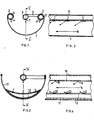
- the channel-shaped drainage channel is designated by the reference number 1.
- the drain channel 1 is designed as a gutter with a semicircular cross-section and has the edge beads 2 typical of gutters on both sides.
- Hollow profiles 3 (tubes) are inserted into the edge beads on both sides and are provided with spray nozzles 4 at regular intervals as seen in the longitudinal direction of the channel 1.
- another hollow profile 5 (tube) which is fastened to an edge bead 2 of the drain channel 1 by means of cross members 6 and is also provided with spray nozzles 7.
- the hollow profiles 3 and 5 (tubes) are advantageously produced as injection-molded parts made of plastic, the spray nozzles 4 and 7 being expediently molded in one piece.
- the hollow profiles 3 and 5 are manufactured separately and subsequently installed in existing drainage channels 1.
- the spray nozzles 4 and 7 in the hollow profiles 3 and 5 are inclined to the direction of the discharge, which is indicated in FIG. 2 by an arrow 8, in such a way that the solids deposited in the discharge channel 1 receive a pulse in the direction of the discharge from the flushing medium emerging from the spray nozzles .
- the spray nozzles 4 assigned to the walls of the drain channel 1 are additionally arranged approximately tangentially to the curved walls of the drain channel 1; so that a liquid cushion forms on the walls, on which the solids float.
- a hollow profile 12 is arranged on the bottom of the drainage channel 11, which is adapted to the cross-sectional shape of the channel 11 and is provided with spray nozzles 13 at regular intervals when viewed in the longitudinal direction.
- the hollow profile 12 and the hollow profile 15 (tube) are made as injection molded parts made of plastic, the spray nozzles 13 and 16 being molded in one piece.
- the hollow profile 12 and the hollow profile 15 (tube) are also manufactured separately and subsequently installed in the existing drainage channel 1.
- the hollow profiles 3, 5, 12 and 15 are connected in a manner not shown to a pump which acts on the spray nozzles 4, 7, 13 and 16 with a pressurized liquid flushing medium.
- the spray nozzles 4, 7, 13 and 16 can also be acted upon by a gaseous or vaporous rinsing medium under high pressure. In this case too, the spray nozzles are supplied with flushing medium via the hollow profiles.
Landscapes
- Engineering & Computer Science (AREA)
- Architecture (AREA)
- Civil Engineering (AREA)
- Structural Engineering (AREA)
- Health & Medical Sciences (AREA)
- Life Sciences & Earth Sciences (AREA)
- Hydrology & Water Resources (AREA)
- Public Health (AREA)
- Water Supply & Treatment (AREA)
- Sink And Installation For Waste Water (AREA)
- Nozzles (AREA)
Description
- Die Erfindung betrifft eine Reinigungseinrichtung für einen Abflußkanal, bestehend aus einem Düsensystem, welches in regelmäßigen Abständen auf die Länge des Kanales verteilt angeordnete Spritzdüsen aufweist, die über mindestens eine entlang dem Kanal verlaufende Spülmittelleitung mit einem unter Druck stehendem Spülmedium beaufschlagbar sind.
- Eine derartige Reinigungseinrichtung ist aus der US-A-2 887 073 bekannt. Die mit Spülmedium beaufschlagbaren Spritzdüsen dienen dazu, den Abflußkanal von sich ablagernden Feststoffen freizuhalten. Zu diesem Zweck werden die Spritzdüsen von Zeit zu Zeit mit einem Spülmedium; beispielsweise Wasser, beaufschlagt. Das aus den Spüldüsen austretende Spülmedium soll die abgelagerten Feststoffe aufwirbeln und fortspülen.
- Die aus der US-A-2 887 073 bekannte Reinigungseinrichtung hat eine Reihe von Nachteilen. Und zwar ist die die Spritzdüsen mit Spülmedium versorgende Spülmittelleitung Bestandteil der Wandung des Abflußkanales. Aus diesem Grunde ist die vorbekannte Reinigungseinrichtung grundsätzlich nicht zur Verwendung an bestehenden Abflußkanälen geeignet. Für die Verwendung der vorbekannten Reinigungseinrichtung ist es also notwendig, den gesamten vorhandenen Abflußkanal gegen einen neuen Abflußkanal auszutauschen. Weiterhin gestaltet sich der Zusammenbau der einzelnen, mit den Spülmittelleitungsab- schnitten versehenen Kanalabschnitte schwierig, weil gleichzeitig mit der Herstellung der Verbindung der Kanalabschnitte eine dichte Verbindung zwischen den in den Wänden der Kanalabschnitte befindlichen Spülleitungsabschnitten hergestellt werden muß. Ein weiterer wesentlicher Nachteil besteht schließlich darin, daß die vorbekannte Reinigungseinrichtung im Hinblick auf ihre Reinigungswirkung unvollkommen ist, weil nur eine unzureichende Strömung in Abflußrichtung erzeugt wird. Die Spritzdüsen verlaufen nämlich bei dieser vorbekannten Reinigungseinrichtung quer zur Abflußrichtung, so daß die Strömung in Abflußrichtung im wesentlichen durch das Gefälle des Abflußkanales erzeugt werden muß.
- Zur Vermeidung der aufgeführten Nachteile ist es aus der US-A-4 183 368 bekannt, im Anfangsbereich des Abflußkanales mittels einer geeigneten, nachträglich montierbaren Befestigungseinrichtung oberhalb des Abflußkanales eine Spritzdüse zu installieren, die über eine Rohrleitung mit Spülmittel versorgt wird und einen kräftigen Spülmittelstrahl erzeugt, der in Strömungsrichtung des Abflußkanales eine intensive, in Abflußrichtung gerichtete Strömung erzeugt.
- Diese nach der US-A-4 183 368 bekannte Reinigungseinrichtung kann zwar auf einfache Weise nachträglich an vorhandenen Abflußkanälen installiert werden, erfordert weniger Aufwand an Material und Montage und hat im Einwirkungsbereich der Spritzdüse auch eine gute Reinigungswirkung, weil der in Abflußrichtung gerichtete Strahl der Spritzdüse die Strömung in Abflußrichtung unterstützt. Sie hat jedoch insofern Nachteile, als sie nur für verhältnismäßig kurze und geradlinig verlaufende Abflußkanäle, z. B. für Dachrinnen von Einfamilienhäusern, verwendbar ist. Bei größerer Länge oder nicht geradlinigem Verlauf des Abflußkanales ist diese Reinigungseinrichtung jedoch ungeeignet, weil sich außerhalb des Einwirkungsbereiches des Strahles der Spritzdüse ein Rückstau bildet, der den Kanal zum Überlaufen bringt.
- Es ist deshalb Aufgabe der Erfindung, die Reinigungseinrichtung der eingangs genannten Art dahingehend weiterzubilden, daß sie für den nachträglichen Einbau in beliebige vorhandene Abflußkanäle geeignet ist, geringe Material- und Montagekosten erfordert und auch bei sehr langen oder nicht geradlinig verlaufenden Abflußkanälen eine gute Reinigungswirkung über die gesamte Länge des Abflußkanales hat.
- Zur Lösung dieser Aufgabe schlägt die Erfindung ausgehend von der Reinigungseinrichtung der eingangs genannten Art vor, daß die Spülmittelleitung aus nachträglich in den Abflußkanal einbaubaren Hohlprofilen besteht, welche in regelmäßigen Abständen mit in Abflußrichtung des Kanales geneigten Spritzdüsen versehen sind.
- Die Reinigungseinrichtung gemäß der Erfindung kann auf besonders vorteilhafte Weise mit wenig Aufwand und Kosten nachträglich an jedem beliebigen Abflußkanal installiert werden. Die in regelmäßigen Abständen direkt an den Hohlprofilen befindlichen, in Abflußrichtung des Kanales geneigten Spritzdüsen erzeugen durch Injektorwirkung unabhängig von der Länge und vom Verlauf des Abflußkanales im gesamten Längenbereich des des Abflußkanales gleichzeitig eine gleichmäßig starke Strömung, die die abgelagerten Feststoffe erfaßt und mitreißt, ohne daß irgendwo im Verlauf des Abflußkanales ein Stau auftreten kann.
- Eine bevorzugte Ausführungsform der Erfindung sieht vor, daß die Hohlprofile als Kunststoff-Spritzgußteile mit angegossenen Spritzdüsen ausgebildet sind. Eine derartige Herstellung der Hohlprofile und der Düsen ist besonders kostengünstig.
- Um besonders hartnäckige Feststoffablagerungen ablösen zu können, sind die Spritzdüsen zweckmäßig zusätzlich mit einem gas- oder dampfförmigen Medium beaufschlagbar.
- Ausführungsbeispiele der Erfindung werden im folgenden anhand der Zeichnung näher erläutert. Es zeigen :
- Fig. 1 einen Querschnitt durch einen als Dachrinne ausgebildeten Abflußkanal gemäß der Erfindung ;
- Fig. 2 einen Längsschnitt entlang der Linie 11-11 in Figur 1 ;
- Fig. 3 einen Querschnitt durch einen Abflußkanal gemäß der Erfindung in einer zweiten Ausführungsform ;
- Fig. 4 einen Längsschnitt entlang der Linie IV-IV in Figur 3.
- In der Zeichnung ist jeweils der rinnenförmige Abflußkanal mit dem Bezugszeichen 1 bezeichnet. Beim Ausführungsbeispiel der Figuren 1 und 2 ist der Abflußkanal 1 als Dachrinne mit halbkreisförmigen Querschnitt ausgebildet und weist an beiden Seiten die für Dachrinnen typischen Randwülste 2 auf. In die Randwülste sind auf beiden Seiten Hohlprofile 3 (Rohre) eingesetzt, die in Längsrichtung des Kanales 1 gesehen in regelmä- ßigen Abständen mit Spritzdüsen 4 versehen sind. Mittig oberhalb des Bodens des Abflußkanales 1 befindet sich ein weiteres Hohlprofil 5 (Rohr), welches mittels Querträgern 6 an einer Randwulst 2 des Abflußkanales 1 befestigt ist und ebenfalls mit Spritzdüsen 7 versehen ist. Die Hohlprofile 3 und 5 (Rohre) sind vorteilhaft als Spritzgußteile aus Kunststoff hergestellt, wobei die Spritzdüsen 4 und 7 zweckmäßig einteilig angespritzt sind. Die Hohlprofile 3 und 5 (Rohre) werden gesondert hergestellt und nachträglich in vorhandene Abflußkanäle 1 eingebaut. Die Spritzdüsen 4 und 7 in den Hohlprofilen 3 und 5 verlaufen geneigt zur Abflußrichtung, die in Figur 2 durch einen Pfeil 8 angedeutet ist, derart, daß die in dem Abflußkanal 1 abgelagerten Feststoffe von dem aus den Spritzdüsen austretenden Spülmedium einen Impuls in der Abflußrichtung erhalten. Dabei sind die den Wänden des Abflußkanales 1 zugeordneten Spritzdüsen 4 zusätzlich etwa tangential zu den gewölbten Wänden des Abflußkanales 1 angeordnet; so daß sich entlang den Wänden ein Flüssigkeitspolster bildet, auf welchem die Feststoffe aufschwimmen.
- Beim Ausführungsbeispiel der Figuren 3 und 4 ist am Boden des Abflußkanales 11 ein Hohlprofil 12 angeordnet, welches der Querschnittsform des Kanales 11 angepaßt ist und in Längsrichtung gesehen in regelmäßigen Abständen mit Spritzdüsen 13 versehen ist. Auch diese Spritzdüsen 13 verlaufen, wie in Figur 4 erkennbar ist, zur Abflußrichtung (Pfeil 14) geneigt, so daß sie den in dem Abflußkanal 11 abgelagerten Feststoffen einen Impuls in der Abflußrichtung (Pfeil 14) erteilen. Auch bei diesem Ausführungsbeispiel befindet sich oberhalb der Mitte des Kanalbodens ein Hohlprofil 15 (Rohr) mit Spritzdüsen 16, welches dem Hohlprofil 5 (Rohr) in den Figuren 1 und 2 entspricht.
- Auch das Hohlprofil 12 und das Hohlprofil 15 (Rohr) sind als Spritzgußteile aus Kunststoff hergestellt, wobei die Spritzdüsen 13 und 16 einteilig angespritzt sind. Auch das Hohlprofil 12 und das Hohlprofil 15 (Rohr) wird gesondert hergestellt und nachträglich in den vorhandenen Abflußkanal 1 eingebaut.
- Die Hohlprofile 3, 5, 12 und 15 sind in nicht näher dargestellter Weise an eine Pumpe angeschlossen, welche die Spritzdüsen 4, 7, 13 und 16 mit einem unter Druck stehendem flüssigen Spülmedium beaufschlagt. Gegebenenfalls können die Spritzdüsen 4, 7, 13 und 16 zusätzlich auch mit einem unter hohem Druck stehenden gas-oder dampfförmigen Spülmedium beaufschlagt werden. Auch in diesem Falle erfolgt die Versorgung der Spritzdüsen mit Spülmedium über die Hohlprofile.
Claims (3)
Priority Applications (1)
| Application Number | Priority Date | Filing Date | Title |
|---|---|---|---|
| AT84105308T ATE47186T1 (de) | 1983-05-11 | 1984-05-10 | Abflusskanal, insbesondere abflussrinne oder abflussrohr. |
Applications Claiming Priority (4)
| Application Number | Priority Date | Filing Date | Title |
|---|---|---|---|
| DE19833317228 DE3317228A1 (de) | 1983-05-11 | 1983-05-11 | Abflusskanal, insbesondere abflussrinne oder abflussrohr |
| DE3317228 | 1983-05-11 | ||
| DE19833319424 DE3319424A1 (de) | 1983-05-28 | 1983-05-28 | Abflusskanal |
| DE3319424 | 1983-05-28 |
Publications (3)
| Publication Number | Publication Date |
|---|---|
| EP0125643A2 EP0125643A2 (de) | 1984-11-21 |
| EP0125643A3 EP0125643A3 (en) | 1986-02-05 |
| EP0125643B1 true EP0125643B1 (de) | 1989-10-11 |
Family
ID=25810700
Family Applications (1)
| Application Number | Title | Priority Date | Filing Date |
|---|---|---|---|
| EP84105308A Expired EP0125643B1 (de) | 1983-05-11 | 1984-05-10 | Abflusskanal, insbesondere Abflussrinne oder Abflussrohr |
Country Status (5)
| Country | Link |
|---|---|
| US (1) | US4634312A (de) |
| EP (1) | EP0125643B1 (de) |
| AU (1) | AU570956B2 (de) |
| CA (1) | CA1248713A (de) |
| DE (1) | DE3480103D1 (de) |
Cited By (2)
| Publication number | Priority date | Publication date | Assignee | Title |
|---|---|---|---|---|
| DE10200623A1 (de) * | 2002-01-10 | 2003-07-31 | Grass Dieter | Dachrinnenreinigungssystem |
| DE102015109717A1 (de) | 2015-06-17 | 2016-12-22 | Dennis Bartsch | Vorrichtung zur Reinigung einer Dachrinne |
Families Citing this family (30)
| Publication number | Priority date | Publication date | Assignee | Title |
|---|---|---|---|---|
| DE3636235A1 (de) * | 1985-10-24 | 1987-04-30 | Erich Sterzel | Duesenanordnung zur erzeugung einer gerichteten stroemung |
| US4899770A (en) * | 1987-04-30 | 1990-02-13 | Wilson R E | Apparatus for preventing deterioration of concrete pipe |
| US4972863A (en) * | 1989-07-19 | 1990-11-27 | Dan Golden | Rain gutter cleaner |
| US5037541A (en) * | 1990-05-30 | 1991-08-06 | Ruey Jang Shiau | Sanitary device for sewerage channel |
| FR2678013B1 (fr) * | 1991-06-18 | 1993-09-17 | Spiess Claude | Gouttiere autonettoyante se deversant dans un caisson muni d'un hachoir. |
| US5119849A (en) * | 1991-07-01 | 1992-06-09 | Hinkley Robert A | Gutter backflush apparatus |
| US5378355A (en) * | 1992-12-04 | 1995-01-03 | Water Pollution Control Corporation | Direct delivery in-situ diffuser cleaning |
| US5727350A (en) * | 1994-02-16 | 1998-03-17 | Marcella; Frank V. | Self-cleaning gutter |
| US5514310A (en) * | 1994-03-25 | 1996-05-07 | Sander; Daniel G. | Method of foaming prior to injection molding |
| US5548931A (en) * | 1995-01-03 | 1996-08-27 | Bryant; Johnnie J. | Quick cleaning gutter system |
| US20040223807A1 (en) * | 1998-12-17 | 2004-11-11 | Joseph Bevilacqua | Self-flushing gutter pipe |
| DE19906224B4 (de) * | 1999-02-15 | 2006-05-24 | Infineon Technologies Ag | Abzugsvorrichtung |
| US6926210B2 (en) * | 2003-08-27 | 2005-08-09 | David Baxter | System for maintaining gutter debris free |
| FR2859914B1 (fr) * | 2003-09-23 | 2007-09-14 | Laurent Sauzade | Gouttiere a double fond anti-incendie |
| US7188784B1 (en) * | 2004-07-17 | 2007-03-13 | Mullins Michael S | Automatic rain gutter flushing system |
| US20060086377A1 (en) * | 2004-10-21 | 2006-04-27 | Micron Technology, Inc. | Self-flushing basement drainage pipe |
| EP2006459A1 (de) * | 2007-06-21 | 2008-12-24 | Herbert Wuersch | Abwasserschacht |
| US20100043831A1 (en) * | 2007-09-26 | 2010-02-25 | Thomas William Koenig | Rain Gutter Member |
| CN102121270A (zh) * | 2011-04-07 | 2011-07-13 | 清华大学深圳研究生院 | 一种用于冲洗排水管道的导管、冲洗管及冲洗系统 |
| WO2015115912A1 (en) * | 2014-01-29 | 2015-08-06 | Wheeler Trevor Edwin | A gutter cleaning system |
| US9074374B1 (en) | 2014-09-04 | 2015-07-07 | Albert Chao | Gutter cleaning apparatus |
| CN105178415A (zh) * | 2015-09-10 | 2015-12-23 | 清华大学深圳研究生院 | 一种合流制排水管道的沉积物处理系统及方法 |
| US9518390B1 (en) | 2016-01-05 | 2016-12-13 | Albert Chao | Self propelled blower |
| AU2018268843B2 (en) * | 2017-05-16 | 2024-03-07 | Xylem Water Solutions Zelienople Llc | Self-cleaning, groutless, filter underdrain |
| US10344481B2 (en) | 2017-07-17 | 2019-07-09 | Daniel J. Song | Self-cleaning gutter system |
| DE102019004306B4 (de) * | 2019-06-18 | 2021-02-04 | Rolf Seelheim | Vorrichtung zur Verhinderung von Schmutzeintrag bei Regenrinnen |
| EP3770357B1 (de) * | 2019-07-23 | 2022-12-28 | Marcel Boschung AG | Gebäude mit einer enteisungseinrichtung |
| US10858838B1 (en) * | 2019-10-29 | 2020-12-08 | Kim Kwee Ng | Debris diversion and removal in a gutter |
| CN111139923B (zh) * | 2020-01-16 | 2025-01-10 | 珠江水利委员会珠江水利科学研究院 | 基于冲击扰动原理的高压气清淤方法 |
| CN111139924B (zh) * | 2020-01-21 | 2025-03-21 | 珠江水利委员会珠江水利科学研究院 | 基于高压喷射的排水管道水利自动清淤方法 |
Family Cites Families (12)
| Publication number | Priority date | Publication date | Assignee | Title |
|---|---|---|---|---|
| US1485499A (en) * | 1921-06-23 | 1924-03-04 | Fleharty Company | Track pan for railroads |
| FR727927A (fr) * | 1931-11-07 | 1932-06-27 | Chantier Et Ateliers De Saint | Dispositif de ramonage des suies dans les chaudières marines ou terrestres |
| US2057691A (en) * | 1933-12-20 | 1936-10-20 | Ranney Leo | Method of and apparatus for excavating |
| US2623234A (en) * | 1950-10-23 | 1952-12-30 | Alvin I Brown | Suction or fluid pressure gutter cleaning apparatus, including a fluid reversing valve |
| US2887073A (en) * | 1955-05-10 | 1959-05-19 | John J Lane | Self-cleaning gutter and downspout attachment to collect debris |
| US3507396A (en) * | 1966-07-25 | 1970-04-21 | Ramsay Homa | Gutters for rainwater |
| CH536703A (de) * | 1972-08-24 | 1973-05-15 | Symalit Ag | Verfahren zur Herstellung einer Kunststoffrinne |
| US3802449A (en) * | 1973-01-05 | 1974-04-09 | L Mulinex | Drain pipe flushing device |
| US4028895A (en) * | 1975-11-14 | 1977-06-14 | Franzmeier Alvin W | Rain gutter attachment |
| US4142370A (en) * | 1977-12-12 | 1979-03-06 | Giordano Louis G | Snap-on end cap for gutters and process for applying same |
| US4183368A (en) * | 1978-06-30 | 1980-01-15 | Husted Gary V | Eave trough flushing system |
| US4407097A (en) * | 1980-02-15 | 1983-10-04 | Allen Jack H | Rain gutter construction |
-
1984
- 1984-05-04 US US06/607,222 patent/US4634312A/en not_active Expired - Fee Related
- 1984-05-08 CA CA000453864A patent/CA1248713A/en not_active Expired
- 1984-05-09 AU AU27819/84A patent/AU570956B2/en not_active Ceased
- 1984-05-10 EP EP84105308A patent/EP0125643B1/de not_active Expired
- 1984-05-10 DE DE8484105308T patent/DE3480103D1/de not_active Expired
Cited By (4)
| Publication number | Priority date | Publication date | Assignee | Title |
|---|---|---|---|---|
| DE10200623A1 (de) * | 2002-01-10 | 2003-07-31 | Grass Dieter | Dachrinnenreinigungssystem |
| DE10200623B4 (de) * | 2002-01-10 | 2005-09-08 | Grass, Dieter | Dachrinnenreinigungssystem |
| DE102015109717A1 (de) | 2015-06-17 | 2016-12-22 | Dennis Bartsch | Vorrichtung zur Reinigung einer Dachrinne |
| DE102015109717B4 (de) * | 2015-06-17 | 2021-02-11 | Dennis Bartsch | Vorrichtung zur Reinigung einer Dachrinne |
Also Published As
| Publication number | Publication date |
|---|---|
| CA1248713A (en) | 1989-01-17 |
| DE3480103D1 (en) | 1989-11-16 |
| US4634312A (en) | 1987-01-06 |
| EP0125643A3 (en) | 1986-02-05 |
| AU2781984A (en) | 1984-11-15 |
| AU570956B2 (en) | 1988-03-31 |
| EP0125643A2 (de) | 1984-11-21 |
Similar Documents
| Publication | Publication Date | Title |
|---|---|---|
| EP0125643A2 (de) | Abflusskanal, insbesondere Abflussrinne oder Abflussrohr | |
| CH665464A5 (de) | Steckmuffendichtung an einem betonrohr. | |
| DE2922888A1 (de) | Filterrohr fuer drainagezwecke | |
| DE2641477A1 (de) | Vorrichtung zum richten eines mediumstroms zu einem fahrzeugscheinwerfer | |
| EP3825480A1 (de) | Spülwasserverteiler | |
| DE3317228A1 (de) | Abflusskanal, insbesondere abflussrinne oder abflussrohr | |
| EP0047482B1 (de) | Abwasserrohr mit Reinigungsöffnung und wegnehmbarer Rückstauklappe | |
| DE102016221650A1 (de) | Fluidverteilerkörper und Sanitärbrause | |
| DE2224519A1 (de) | Ein- oder mehrstufiger waescher | |
| DE2261674A1 (de) | Vorrichtung zum ansaugen und beimischen von zusatzstoffen in einen fluessigkeitsstrom | |
| EP0563081B1 (de) | Verfahren zum reinigen eines tropfenabscheiders und tropfenabscheider mit reinigungsvorrichtung | |
| EP0198073B1 (de) | Vorrichtung zur einbringung eines gases in einer flüssigkeit | |
| DE2704663A1 (de) | Rohranschluss fuer abortbecken und verfahren zu seiner herstellung | |
| DE2412988A1 (de) | Anlage zum waschen eines verschmutzten gases | |
| EP0643177A1 (de) | Urinal | |
| DE2533968C3 (de) | Aus zumindest zwei miteinander verbundenen Rohrschüssen aus thermoplastischen Kunststoff zusammengesetzte Rohrleitung für Kanalsickersysteme | |
| DE9309852U1 (de) | Befestigungseinrichtung an einem Kraftfahrzeug-Scheinwerfer oder einer -Leuchte für ein Waschgerät | |
| DE19757438B4 (de) | Einrichtung zur lösbaren Montage von Sprühdüsenlanzen in Gaswaschern | |
| DE8315702U1 (de) | Abflusskanal | |
| DE2437644B2 (de) | Sauerstofflanze für Konverter | |
| DE8314018U1 (de) | Abflusskanal, insbesondere abflussrinne oder abflussrohr | |
| DE3518951A1 (de) | Speicher- u. spuelvorrichtung fuer ein zeitweise gefuelltes becken insbesondere fuer ein regenbecken | |
| DE2306321C3 (de) | Einrichtung zum Erhöhen des Mengenstromes durch Ablauf rohre · | |
| DE69800509T2 (de) | Abwasserkanal | |
| DE2909696A1 (de) | Filterduese zum einsetzen in wandoeffnungen, insbesondere der zwischenboeden von fluessigkeitsbehaeltern |
Legal Events
| Date | Code | Title | Description |
|---|---|---|---|
| PUAI | Public reference made under article 153(3) epc to a published international application that has entered the european phase |
Free format text: ORIGINAL CODE: 0009012 |
|
| AK | Designated contracting states |
Designated state(s): AT BE CH DE FR GB IT LI NL SE |
|
| PUAL | Search report despatched |
Free format text: ORIGINAL CODE: 0009013 |
|
| AK | Designated contracting states |
Designated state(s): AT BE CH DE FR GB IT LI NL SE |
|
| 17P | Request for examination filed |
Effective date: 19860731 |
|
| 17Q | First examination report despatched |
Effective date: 19870320 |
|
| GRAA | (expected) grant |
Free format text: ORIGINAL CODE: 0009210 |
|
| ITF | It: translation for a ep patent filed | ||
| AK | Designated contracting states |
Kind code of ref document: B1 Designated state(s): AT BE CH DE FR GB IT LI NL SE |
|
| REF | Corresponds to: |
Ref document number: 47186 Country of ref document: AT Date of ref document: 19891015 Kind code of ref document: T |
|
| REF | Corresponds to: |
Ref document number: 3480103 Country of ref document: DE Date of ref document: 19891116 |
|
| GBT | Gb: translation of ep patent filed (gb section 77(6)(a)/1977) | ||
| ET | Fr: translation filed | ||
| PLBE | No opposition filed within time limit |
Free format text: ORIGINAL CODE: 0009261 |
|
| STAA | Information on the status of an ep patent application or granted ep patent |
Free format text: STATUS: NO OPPOSITION FILED WITHIN TIME LIMIT |
|
| 26N | No opposition filed | ||
| ITTA | It: last paid annual fee | ||
| PGFP | Annual fee paid to national office [announced via postgrant information from national office to epo] |
Ref country code: GB Payment date: 19920511 Year of fee payment: 9 |
|
| PGFP | Annual fee paid to national office [announced via postgrant information from national office to epo] |
Ref country code: CH Payment date: 19920512 Year of fee payment: 9 |
|
| PGFP | Annual fee paid to national office [announced via postgrant information from national office to epo] |
Ref country code: AT Payment date: 19920519 Year of fee payment: 9 |
|
| PGFP | Annual fee paid to national office [announced via postgrant information from national office to epo] |
Ref country code: SE Payment date: 19920521 Year of fee payment: 9 |
|
| PG25 | Lapsed in a contracting state [announced via postgrant information from national office to epo] |
Ref country code: AT Effective date: 19930510 Ref country code: GB Effective date: 19930510 |
|
| PG25 | Lapsed in a contracting state [announced via postgrant information from national office to epo] |
Ref country code: SE Effective date: 19930511 |
|
| PGFP | Annual fee paid to national office [announced via postgrant information from national office to epo] |
Ref country code: BE Payment date: 19930525 Year of fee payment: 10 |
|
| PGFP | Annual fee paid to national office [announced via postgrant information from national office to epo] |
Ref country code: FR Payment date: 19930527 Year of fee payment: 10 |
|
| PG25 | Lapsed in a contracting state [announced via postgrant information from national office to epo] |
Ref country code: LI Effective date: 19930531 Ref country code: CH Effective date: 19930531 |
|
| PGFP | Annual fee paid to national office [announced via postgrant information from national office to epo] |
Ref country code: NL Payment date: 19930531 Year of fee payment: 10 |
|
| PGFP | Annual fee paid to national office [announced via postgrant information from national office to epo] |
Ref country code: DE Payment date: 19930730 Year of fee payment: 10 |
|
| GBPC | Gb: european patent ceased through non-payment of renewal fee |
Effective date: 19930510 |
|
| REG | Reference to a national code |
Ref country code: CH Ref legal event code: PL |
|
| PG25 | Lapsed in a contracting state [announced via postgrant information from national office to epo] |
Ref country code: BE Effective date: 19940531 |
|
| BERE | Be: lapsed |
Owner name: STERZEL ERICH Effective date: 19940531 |
|
| PG25 | Lapsed in a contracting state [announced via postgrant information from national office to epo] |
Ref country code: NL Effective date: 19941201 |
|
| NLV4 | Nl: lapsed or anulled due to non-payment of the annual fee | ||
| EUG | Se: european patent has lapsed |
Ref document number: 84105308.5 Effective date: 19931210 |
|
| PG25 | Lapsed in a contracting state [announced via postgrant information from national office to epo] |
Ref country code: FR Effective date: 19950131 |
|
| PG25 | Lapsed in a contracting state [announced via postgrant information from national office to epo] |
Ref country code: DE Effective date: 19950201 |
|
| REG | Reference to a national code |
Ref country code: FR Ref legal event code: ST |