EP0125664A1 - Compteur de fluide à piston rotatif avec porte intérieure avec diamètre intérieur contrôlé du piston rotatif - Google Patents
Compteur de fluide à piston rotatif avec porte intérieure avec diamètre intérieur contrôlé du piston rotatif Download PDFInfo
- Publication number
- EP0125664A1 EP0125664A1 EP84105380A EP84105380A EP0125664A1 EP 0125664 A1 EP0125664 A1 EP 0125664A1 EP 84105380 A EP84105380 A EP 84105380A EP 84105380 A EP84105380 A EP 84105380A EP 0125664 A1 EP0125664 A1 EP 0125664A1
- Authority
- EP
- European Patent Office
- Prior art keywords
- gate
- rotor
- vane
- vanes
- fluid
- Prior art date
- Legal status (The legal status is an assumption and is not a legal conclusion. Google has not performed a legal analysis and makes no representation as to the accuracy of the status listed.)
- Granted
Links
- 239000012530 fluid Substances 0.000 title claims abstract description 91
- 230000000979 retarding effect Effects 0.000 claims description 10
- 230000008878 coupling Effects 0.000 claims 2
- 238000010168 coupling process Methods 0.000 claims 2
- 238000005859 coupling reaction Methods 0.000 claims 2
- 230000006835 compression Effects 0.000 description 26
- 238000007906 compression Methods 0.000 description 26
- 230000000694 effects Effects 0.000 description 26
- 230000002829 reductive effect Effects 0.000 description 18
- 238000013461 design Methods 0.000 description 15
- 238000007789 sealing Methods 0.000 description 13
- 230000008901 benefit Effects 0.000 description 6
- 239000007789 gas Substances 0.000 description 6
- 230000007246 mechanism Effects 0.000 description 6
- 230000009467 reduction Effects 0.000 description 6
- 238000010276 construction Methods 0.000 description 5
- 238000000034 method Methods 0.000 description 5
- 230000037303 wrinkles Effects 0.000 description 5
- 230000009471 action Effects 0.000 description 4
- 230000002411 adverse Effects 0.000 description 4
- 238000013459 approach Methods 0.000 description 4
- 238000005259 measurement Methods 0.000 description 4
- 230000009286 beneficial effect Effects 0.000 description 3
- 230000008859 change Effects 0.000 description 3
- 238000006073 displacement reaction Methods 0.000 description 3
- 230000002093 peripheral effect Effects 0.000 description 3
- 238000012360 testing method Methods 0.000 description 3
- 230000007423 decrease Effects 0.000 description 2
- 230000000670 limiting effect Effects 0.000 description 2
- 239000007788 liquid Substances 0.000 description 2
- VNWKTOKETHGBQD-UHFFFAOYSA-N methane Chemical compound C VNWKTOKETHGBQD-UHFFFAOYSA-N 0.000 description 2
- 230000004048 modification Effects 0.000 description 2
- 238000012986 modification Methods 0.000 description 2
- 230000004044 response Effects 0.000 description 2
- 230000002441 reversible effect Effects 0.000 description 2
- 238000007493 shaping process Methods 0.000 description 2
- 230000000007 visual effect Effects 0.000 description 2
- XLYOFNOQVPJJNP-UHFFFAOYSA-N water Substances O XLYOFNOQVPJJNP-UHFFFAOYSA-N 0.000 description 2
- 230000004075 alteration Effects 0.000 description 1
- 238000010586 diagram Methods 0.000 description 1
- 238000013551 empirical research Methods 0.000 description 1
- 230000001050 lubricating effect Effects 0.000 description 1
- 238000004519 manufacturing process Methods 0.000 description 1
- 239000003345 natural gas Substances 0.000 description 1
- 238000004904 shortening Methods 0.000 description 1
- 238000004088 simulation Methods 0.000 description 1
- 230000007704 transition Effects 0.000 description 1
- 238000009966 trimming Methods 0.000 description 1
- 238000012800 visualization Methods 0.000 description 1
Images


Classifications
-
- F—MECHANICAL ENGINEERING; LIGHTING; HEATING; WEAPONS; BLASTING
- F02—COMBUSTION ENGINES; HOT-GAS OR COMBUSTION-PRODUCT ENGINE PLANTS
- F02M—SUPPLYING COMBUSTION ENGINES IN GENERAL WITH COMBUSTIBLE MIXTURES OR CONSTITUENTS THEREOF
- F02M31/00—Apparatus for thermally treating combustion-air, fuel, or fuel-air mixture
-
- G—PHYSICS
- G01—MEASURING; TESTING
- G01F—MEASURING VOLUME, VOLUME FLOW, MASS FLOW OR LIQUID LEVEL; METERING BY VOLUME
- G01F3/00—Measuring the volume flow of fluids or fluent solid material wherein the fluid passes through the meter in successive and more or less isolated quantities, the meter being driven by the flow
- G01F3/02—Measuring the volume flow of fluids or fluent solid material wherein the fluid passes through the meter in successive and more or less isolated quantities, the meter being driven by the flow with measuring chambers which expand or contract during measurement
- G01F3/04—Measuring the volume flow of fluids or fluent solid material wherein the fluid passes through the meter in successive and more or less isolated quantities, the meter being driven by the flow with measuring chambers which expand or contract during measurement having rigid movable walls
- G01F3/06—Measuring the volume flow of fluids or fluent solid material wherein the fluid passes through the meter in successive and more or less isolated quantities, the meter being driven by the flow with measuring chambers which expand or contract during measurement having rigid movable walls comprising members rotating in a fluid-tight or substantially fluid-tight manner in a housing
Definitions
- This invention relates to fluid meters and, more particularly, to a fluid meter of the internal gate rotary vane type.
- Rotary vane-type fluid meters with an internal sealing gate generally exhibit excellent performance characteristics compared to other types of rotary positive displacement meters (such as the lobed impeller or external sealing gate type meters). As a general rule, the reason for better performance is better fluid flow through the meter and lower friction of the moving parts.
- Fluid meters have exacting requirements for minimum performance. For a given full capacity rating, a meter must not exceed some standard of maximum pressure drop, or differential, across the meter connections (as this is a measure of its lack of friction and flow impediments). For gaseous rotary meters this standard is presently one inch water column (1/27 psig) at full capacity on natural gas (0.6 S.G.) where the inlet is at seven inches water column (1/4 psig) over atmospheric pressure. As some pressure differential would normally occur across a pipe of equal length, connection to connection, such a requirement dictates low friction of mechanism and minimal fluid flow impediments. It follows that designs having lower mechanical friction and fewer flow impediments have a higher capacity and thus more commercial value.
- Another measure of fluid meter performance is accuracy of measuring actual volume from low flow rates to capacity. While 100% accuracy is desirable at all flow rates, it is recognized as being impossible. Accordingly, industry standards use a minimum level of performance which allow some deviations in accuracy. In the United States for gaseous rotary meters this standard presently is a band of + 1% around 100% accuracy for flow rates which the meter must meet during many years of operation without calibration, at all rated pressures, and in all conceivable ambient temperatures. Therefore, a meter with minimal friction and fewer flow impediments is more likely to meet accuracy requirements given such operating conditions.
- Rangeability is defined, for gaseous meters, as the ratio of full flow rate divided by that lower flow rate which falls out of the accuracy band of 100% +1%. Rangeability is expressed as a ratio (such as 20:1 which would mean the meter's accuracy was falling below 99% at 5% of full flow). This performance criteria is a very sensitive measure of the meter's mechanical friction and/or freedom from compression/suction cycles as these cause the rotating components to try to operate slower than the gas velocity, which results in blowby at the seals. Rangeability can also be a measure of the sealing effectiveness (seal blowby at a given differential), but mechanical friction and/or compression/suction cycles cause the increased pressure differential to drive fluids through the seal.
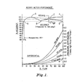
- FIG. 1 illustrates a typical performance chart for a gaseous rotary meter.
- the highest accuracy values cannot exceed 101% (see Points B and C) and the lowest accuracy values cannot be lower than 99%, including compression frequencies (see Point D) and "boost” or “droop” at full capacity (Point E is a "droop", F is a "boost”).
- the Rangeability of this example is 20:1 (or 100%+ 5%, the point at which the accuracy curve falls below 99%, Point G).
- the flange-to-flange pressure differential cannot exceed 1.0" H 2 0 (see Point H) for 7.0" H 2 0 inlet pressure.
- a rotary meter having a high operating pressure differential due to mechanical friction or flow impediments would result in the capacity being lowered until the 1.0" H 2 0 differential were met.
- a rotary meter with substantial compressive cycles might not even qualify to the standard.
- a rotary meter with high rotational velocity friction due to such items as geared gate driving mechanisms, bearings, lubricating baths, and seals, or flow rate related impediments, might have excessive "droop" as to limit capacity.
- a rotary meter whose accuracy is adversely affected by pressure might not qualify.
- a rotary meter having high tare friction (and possibly poor sealing) might substantially reduce rangeability.
- a fluid meter having a gate with at least two pockets which rotates at the same velocity as a rotor having the same number of vanes and wherein the inner diameter of the rotor vanes is controlled to provide a properly sized orifice between the vane inner diameter surface and the gate hub so as to provide a driving torque to the gate due to the passage of the vanes through the gate pocket, the gate driving torque being balanced to match gate retarding torques due to friction of the gate drive train and friction of the gate bearings.
- FIGS. 2A-2F are section views of a contemporary meter showing rotor 10, rotor vanes 11, 12, 13 and 14, gate 30, gate pockets 31 and 32, housing 50, inlet port 51, outlet port 52, and sealing crescent 53.
- Such construction can be observed in Wrinkle's Patent No. 3,482,446 as improved by Schneider's Patent No. 4,109,528 and Schneider's Patent No. 3,554,032 as improved by Schneider's Patent No. 3,842,672.
- These patents cover the only known commercially available vane-type rotary meters with an internal seal gate.
- FIG. 2A it can be observed that incoming fluid can fill the inlet cavity 54 until stopped by the seal gate 30 and vane 12.
- the seals on gate 30 are effected against the housing 50 at the gate cavity 55 at the point 33 and against the sealing crescent 53 at the point 34.
- These seal points 33 and 34 must be sufficiently tight (small clearance) and long enough to substantially impede fluid flow when the outlet port 52 is at a lower pressure than the inlet port 51.
- the seals on the rotor vane 12 are effected at the housing 50 at the rotor 10 outer diameter at point 15 and at the inner diameter at point 16 against the crescent 53. Again the seal points 15 and 16 must be sufficiently tight and long enough to substantially impede fluid flow.
- the gate 30 is also driven counterclockwise (generally by timing gearing) so as to synchronize the gate pocket 31 with the passage of the leaving vane 11 and the gate pocket 32 with the returning vane 14.
- timing gearing generally by timing gearing
- FIG. 2C a portion of fluid has now been trapped between vanes 11 and 12 which, for these illustrations, becomes the measured actual volume.
- the measured volume also includes the gate pocket 31 volume less the returning gate pocket 32 volume, the latter being smaller because of the vane 14 displacement which makes up for half each of vanes 11 and 12 displacement. This is why the capacity of the meter is the swept area of the vanes and ignores the vane thickness.
- FIGS. 2D-2F continue the cycle until, in FIG. 2F, the measured gas is expelled to the outlet port 52.
- FIGS. 2A-2F show a 2 pocket gate and 4 vane rotor with relative rotational velocities in the ratio of 2 to 4; i.e., the gate 30 rotational velocity is twice (200%) that of the rotor 10. It is well known that any other ratio which synchronizes the vanes into gate pockets will work (but is not necessarily preferred) as long as there are at least two vanes (required for sealing).
- FIG. 3 allows the viewer to maintain a constant perspective of a gate pocket while observing the passage of a rotor vane with respect to rotational position.
- the example shown is the FIG. 2A-2F example of 2 gate pocket/4 rotor vane configuration with the gate rotational velocity being twice the rotor rotational velocity. It would appear, from examination of FIG. 3, that fluid turbulence is relatively minimal in the pocket (especially compared to lobed or external gate designs), and indeed it is. However, further examination reveals that there are some compression/suction cycles even with a good basic entry and exit of the vane in a gate pocket.
- FIG. 3 allows the viewer to maintain a constant perspective of a gate pocket while observing the passage of a rotor vane with respect to rotational position.
- the example shown is the FIG. 2A-2F example of 2 gate pocket/4 rotor vane configuration with the gate rotational velocity being twice the rotor rotational velocity. It would appear, from examination of FIG. 3, that fluid turbulence is relatively minimal in the pocket
- FIG. 4 shows the FIG. 2B position of FIG. 3 crosshatched with an area of fluid 36 dotted.
- FIG. 5 shows the FIG. 2C position of FIG. 3 crosshatched with the same area of fluid 36 dotted.
- the vane 14 (at FIG. 2C crosshatched) has now completely entered the pocket 32.
- the entry of the vane 14 displaced some fluid (that area of the vane under the line 40) and it can be presumed that half of the displaced fluid went to either side of the vane 14.
- That portion of the fluid displaced by the vane 14 pertinent to the discussion is 41 (it causes a compression to area 36).
- the vane 14 has vacated an area 42 (shown as joined circles) which is a suction to area 36.
- Area 42 (the suction) is larger than area 41 (the compression) so the net effect is a suction on area 36.
- the rotor 10 is the driving force in a meter (due to pressure differential from inlet to outlet).
- the rotor 10 through some driving mechanism (like gears) causes the gate 30 to be driven. While the drive to the gate 30 is a modest torque, it should be noted that it is through a 200% speed increaser (for a 2 pocket gate, 4 vane rotor); which more than doubles the required torque from the rotor 10 to drive the gate 30. It is more than double the torque because gear train and bearing friction increase with rotational velocity.
- FIG. 6 shows a diagram of resultant forces. It can be seen in FIG.
- Such a 2 pocket/4 vane rotor arrangement can also be observed to have, of the possible available combinations of gate/rotor ratios, the one of the higher gate rotational velocities which results in higher gate drive train frictions, higher gate bearing rotational velocities and resultant friction (which also lowers bearing life), and has higher rotating element inertia (if the mass and diameters of components are identical).
- FIG. 7 uses the technique of FIGS. 3-5 to show the characteristics of vane entry/exit to a gate pocket. It can be observed in FIG. 7 that the vane entry/exit is not like the FIG. 3 example. In FIG. 7, the vane 21 has a higher angle of attack to the gate pocket 22.
- an additional benefit of this 1:1 ratio is that other types of gate driving mechanism (than gear trains) are possible.
- Another benefit is that the inertia of rotating elements is minimized (for rotating elements of the same diameter and mass). Reduction in rotating component inertia allows the meter to be more responsive to changes in fluid flow rate, improves measured accuracy during a change in flow rate (lower inertia reduces the pressure differential across the rotating elements which reduces seal blowby), reduces mechanical strain on components due to sudden, major changes in flow rate, reduces the mechanical strain on the gate drive train, and reduces the overrun/reverse characteristics of rotary meters which occurs when the flow rate is quickly reduced (such as the reduction of a burner to a pilot flame) which can extinguish ("suck-out") a pilot.
- Another benefit is that bearing velocity of the gate components is reduced so that bearing life is improved.
- the preferred embodiment should have a 1:1 gate to rotor rotational velocity ratio of at least 2 gate pockets/2 rotor vanes where the aiding forces of the vane passage through the gate pocket is balanced (by trimming the vane inner diameter to provide the desired orifice 26) against the forces of the gate drive friction and gate bearing friction.
- Proper dimensions of the orifice 26 are obtained through empirical testing, since different sized meters have different bearings, etc., which results in different retarding forces. Additional benefits of this lowest practical ratio are lowest gate drive friction, lowest gate bearing friction, and lowest inertia of rotating components (for a given diameter and mass of rotating components). The effect on meter performance is to improve and stabilize accuracy over wide flow rates and to reduce pressure differential (which improves capacity) and to improve rangeability.
- rotor, gate, and crescent geometry Another consideration is rotor, gate, and crescent geometry.
- rotational velocity friction By minimizing rotational velocity friction, inaccuracies due to variable friction are minimized and rangeability is improved (increase in ratio).
- the objective in selecting geometry is therefore to minimize component rotational velocity.
- the capacity per revolution of a rotary vane meter is the swept area of a rotor vane in one revolution.
- the vane 46 outer diameter is D r
- the vane 46 inner diameter is D i
- the vane 46 length is L v
- the swept volume (or capacity) V in one revolution is a cylinder having a volume as follows:
- D i has some constraints to reducing its diameter.
- one major constraint is that the gate bearing hub diameter D h must be inside the vane inner diameter D i so that the vane 11 can pass the gate 30.
- Another major constraint is that the gate hub must have a vane inner tip orifice 38 for balancing vane driving torque to friction (as previously discussed).
- FIG. 9 capacity per revolution (V in FIG. 9) can be maximized for a given rotor diameter D r and vane length (Z v in FIG. 9) if the vane inner diameter D i is minimized by increasing the gate to its maximum diameter D g (which still seals).
- FIGS. 11 and 12 demonstrate the effect of D i if the gate diameter D g is maximized (within its constraints).
- FIG. 13A shows a 3 vane rotor and FIG. 13B shows a 4 vane rotor which have an increased gate diameter D g which still seals appropriately.
- D g the gate diameter of the rotor vane inner diameter D i to its minimum value.
- This maximizes the volume V for a given rotor outer diameter D and vane length L.
- This reduction in friction improves meter performance; variances in accuracy due to friction are reduced, pressure differential to drive the rotor is reduced (thus capacity rating is increased), and rangeability can be improved both due to lower rotating friction as well as lower driving pressure differential.
- the rotating inertia is reduced in proportion to rotating velocity for the rotor, and to a lesser degree for the gate (as it is a larger diameter). This improves meter response during changes in flow rate.
- an internal gate vane-type rotary meter in order to reduce rotating velocity for the purpose of reducing rotating friction to improve meter accuracy, and in order to reduce rotating inertia for the purpose of improving meter response and accuracy during changes in flow rate, an internal gate vane-type rotary meter should be designed to maximize the gate diameter. It is possible to maximize the gate diameter by reducing the crescent sealing arc to:
- rotor vane length (L v in FIG. 9). It has been the practice in rotary meter design to maximize the length of vanes (length parallel) to the axis of rotor rotation) within the constraints of mechanical construction. For instance, contemporary 4 vaned rotors with a rotor end plate on both ends have a vane length L v to rotor diameter D r ratio of 1:1. Contemporary 3 vaned rotors with cantilevered vanes from one rotor end plate have a vane length L v to rotor diameter D ratio of 1:2. These constructions are illustrated r in FIGS. 14A and 14B, respectively.
- FIGS. 15A and 15B graphically illustrates this aspect ratio issue.
- Such fluid dynamic effects are proportional to fluid mass; thus the adverse effects of a higher aspect ratio is more pronounced at higher (i.e., capacity) flow rates and when the fluid's mass increases (i.e., at higher pressures for gaseous fluids).
- another reason to limit the aspect ratio is to minimize effects of gas density.
- Another effect of limiting the aspect ratio is that increasing the rotor diameter to compensate for reduced vane length results in improved volumetric efficiency (the ratio of the swept volume to the volume occupied by the mechanism), because as shown in FIG. 9, the swept volume is related to the second power of the diameter ( D 2 ) but only to the first power of the vane length (L v ): this allows a lower rotational velocity of the rotor. As previously observed, slowing component rotational velocity reduces rotating friction proportionately. It should be noted, however, that rotational inertia is reduced in proportion to the lower rotational velocity but increased due to the outward movement of rotating component mass (rotating component design must attempt to minimize mass towards the component periphery).
- Another effect of limiting the aspect ratio by increasing the rotor diameter and shortening rotor vanes is that the starting torque is increased in proportion to the increase in diameter of the rotor (the force, pressure differential, of liquid against the rotor vane has a larger moment arm around the rotor centerline).
- This increase in starting torque is highly beneficial to rangeability as the rotating components more readily overcome tare friction of gate drive and bearings allowing the rotor to more nearly match the velocity of the measured fluid at low flow rates (which are also at very low pressure differentials).
- This additional torque is also very beneficial in driving devices powered by a rotor (such as mechanical volume correctors).
- FIG. 17 shows a typical method.
- the problem with the method shown in FIG. 17, however, is that fluids tend (due to their mass) to continue in the same direction and velocity as their initial direction and velocity in the entrance pipe or as exiting the meter outlet chamber 75.
- pressure differential is one of the parameters of meter rating.
- FIG. 18 shows this schematically. In the schematic FIG. 18, (and referring to FIG.
- FIGS. 13A and 13B disclose this principle.
- the amount of fluid turning can be substantially reduced depending on the number of vanes on the rotor; from 360° arc to 240° arc for a 3 vane rotor (FIG. 19A), and from 360° arc to 180° arc for a 4 vane rotor (FIG. 19B).
- the radius R 1 for the inlet conduits 79, 81 and the radius R 2 for the outlet conduits 80, 82 can be made larger (more gentle turn) without significantly increasing the flange-to-flange dimension W f .
- the result of this approach is to significantly lower the differential pressure required to pass fluid through the housing (without rotating elements). Benefits are higher capacity rating for a given pipe size and reduction in gaseous fluid density effects as might occur with higher pressures.
- the preferred embodiment is a 3 vane rotor (due to the geometry of rotating elements in a 1:1 ratio of gate to rotor rotational velocities with a maximized gate diameter and balanced torque orifice as herein described).
- the suction and compression points next to the gate are significantly detached from the fluid flow as shown in FIGS. 19A and 19B but absolutely require fluid flow.
- the tapered fluid inlet and outlet chambers are required for proper fluid feed and exit to gate and rotor.
- a "practical" meter housing 83 which minimizes pressure differential losses due to fluid dynamic considerations of turning and changes in velocity.
- the rotor 100 and gate 101 are mounted on the housing 83 for rotation about parallel displaced axes. If the inlet pipe fluid flow and cross-sectional area is considered to be 100%, then chamber 84 also is 100% (but can be used to convert from the circular pipe inner diameter to rectangular shape as a transition). Turning vane 85 splits the 100% into the fluid flow requirement behind the turning vanes at the rotor (the tapered inlet chamber 73 of FIG.
- the result to performance is improved accuracy (particularly at full capacity) and reduced aberrations of accuracy due to gaseous fluid density (as at higher operating pressures).
- a housing configuration for in-line piping of conduits and turning vanes structured to fulfill the fluid feeding requirements at the rotor while directing most of the fluid flow through gently curving conduits which reduce the typical 360° arc of fluid flow through the meter to 240° of arc thus improving accuracy at high flow rates and/or at higher operating pressures.
- the reduced crescent (under 180° of arc) is a prerequisite to this design.
Landscapes
- Engineering & Computer Science (AREA)
- Physics & Mathematics (AREA)
- Fluid Mechanics (AREA)
- General Physics & Mathematics (AREA)
- Chemical & Material Sciences (AREA)
- Combustion & Propulsion (AREA)
- Mechanical Engineering (AREA)
- General Engineering & Computer Science (AREA)
- Measuring Volume Flow (AREA)
- Rotary Pumps (AREA)
Applications Claiming Priority (2)
| Application Number | Priority Date | Filing Date | Title |
|---|---|---|---|
| US494206 | 1983-05-13 | ||
| US06/494,206 US4487064A (en) | 1983-05-13 | 1983-05-13 | Internal gate rotary vane fluid meter with controlled rotor vane inner diameter |
Publications (2)
| Publication Number | Publication Date |
|---|---|
| EP0125664A1 true EP0125664A1 (fr) | 1984-11-21 |
| EP0125664B1 EP0125664B1 (fr) | 1987-11-11 |
Family
ID=23963499
Family Applications (1)
| Application Number | Title | Priority Date | Filing Date |
|---|---|---|---|
| EP84105380A Expired EP0125664B1 (fr) | 1983-05-13 | 1984-05-11 | Compteur de fluide à piston rotatif avec porte intérieure avec diamètre intérieur contrôlé du piston rotatif |
Country Status (9)
| Country | Link |
|---|---|
| US (1) | US4487064A (fr) |
| EP (1) | EP0125664B1 (fr) |
| JP (1) | JPS59212717A (fr) |
| KR (1) | KR850000062A (fr) |
| AU (1) | AU564407B2 (fr) |
| BR (1) | BR8402288A (fr) |
| CA (1) | CA1201306A (fr) |
| DE (2) | DE125664T1 (fr) |
| DK (1) | DK236184A (fr) |
Families Citing this family (3)
| Publication number | Priority date | Publication date | Assignee | Title |
|---|---|---|---|---|
| US5513529A (en) * | 1991-06-07 | 1996-05-07 | Liquid Controls Corporation | Housing assembly for flow meter |
| DE202017106254U1 (de) * | 2017-10-16 | 2019-01-17 | Flaco-Geräte GmbH | Durchflussmessgerät |
| CN110645237B (zh) * | 2019-09-02 | 2022-01-14 | 厦门理工学院 | 一种管道导流装置 |
Citations (2)
| Publication number | Priority date | Publication date | Assignee | Title |
|---|---|---|---|---|
| US3842672A (en) * | 1973-05-09 | 1974-10-22 | Singer Co | Flow profiler for high pressure rotary meters |
| GB2059509A (en) * | 1979-09-24 | 1981-04-23 | Singer Co | Rotary fluid meter |
Family Cites Families (3)
| Publication number | Priority date | Publication date | Assignee | Title |
|---|---|---|---|---|
| US1994397A (en) * | 1933-03-23 | 1935-03-12 | Loveridge Claude Warren | Rotary engine |
| US3482446A (en) * | 1966-04-25 | 1969-12-09 | American Meter Co | Fluid meter |
| GB1455422A (en) * | 1973-10-03 | 1976-11-10 | Dresser Europe Sa | Rotary liquid flow meter |
-
1983
- 1983-05-13 US US06/494,206 patent/US4487064A/en not_active Expired - Fee Related
-
1984
- 1984-03-23 CA CA000450318A patent/CA1201306A/fr not_active Expired
- 1984-05-03 AU AU27652/84A patent/AU564407B2/en not_active Ceased
- 1984-05-10 JP JP59093821A patent/JPS59212717A/ja active Pending
- 1984-05-11 EP EP84105380A patent/EP0125664B1/fr not_active Expired
- 1984-05-11 DK DK236184A patent/DK236184A/da not_active Application Discontinuation
- 1984-05-11 DE DE198484105380T patent/DE125664T1/de active Pending
- 1984-05-11 BR BR8402288A patent/BR8402288A/pt unknown
- 1984-05-11 DE DE8484105380T patent/DE3467404D1/de not_active Expired
- 1984-05-12 KR KR1019840002563A patent/KR850000062A/ko not_active Withdrawn
Patent Citations (2)
| Publication number | Priority date | Publication date | Assignee | Title |
|---|---|---|---|---|
| US3842672A (en) * | 1973-05-09 | 1974-10-22 | Singer Co | Flow profiler for high pressure rotary meters |
| GB2059509A (en) * | 1979-09-24 | 1981-04-23 | Singer Co | Rotary fluid meter |
Also Published As
| Publication number | Publication date |
|---|---|
| KR850000062A (ko) | 1985-02-25 |
| DE3467404D1 (de) | 1987-12-17 |
| DK236184A (da) | 1984-11-14 |
| AU564407B2 (en) | 1987-08-13 |
| EP0125664B1 (fr) | 1987-11-11 |
| CA1201306A (fr) | 1986-03-04 |
| JPS59212717A (ja) | 1984-12-01 |
| DE125664T1 (de) | 1985-02-14 |
| BR8402288A (pt) | 1984-12-18 |
| DK236184D0 (da) | 1984-05-11 |
| US4487064A (en) | 1984-12-11 |
| AU2765284A (en) | 1984-11-15 |
Similar Documents
| Publication | Publication Date | Title |
|---|---|---|
| CA1131498A (fr) | Pompe axiale volumetrique polyvalent | |
| US4534227A (en) | Device for measuring the flow of a fluid | |
| CN100494915C (zh) | 异型腔流量计 | |
| US4479384A (en) | Internal gate rotary vane fluid meter with improved element geometry | |
| US4487064A (en) | Internal gate rotary vane fluid meter with controlled rotor vane inner diameter | |
| US3756079A (en) | Turbine flowmeter | |
| EP0125663B1 (fr) | Compteur de fluide à piston rotatif muni d'une porte intérieure avec proportion contrôlée de longueur du piston rotatif | |
| EP0125661B1 (fr) | Compteur de fluide à piston rotatif avec porte intérieure avec passage d'admission et d'échappement contourné | |
| US3613451A (en) | Mass flowmeter | |
| US3842672A (en) | Flow profiler for high pressure rotary meters | |
| US3482446A (en) | Fluid meter | |
| JPS6328246B2 (fr) | ||
| US3301052A (en) | Turbine flowmeter | |
| US4827767A (en) | Flow meter | |
| US2262231A (en) | Liquid metering device | |
| US6065352A (en) | Turbine meter with a rotor having accuracy enhancing rotor blades | |
| US2843094A (en) | Positive displacement type fluid meter | |
| CN223623651U (zh) | 流量计 | |
| RU2126144C1 (ru) | Счетчик газа и жидкости | |
| CN201548265U (zh) | 一种浮动内齿轮式低脉动齿轮流量计 | |
| RU2327957C1 (ru) | Роликолопастной расходомер | |
| SU870946A1 (ru) | Ротационный счетчик жидкости | |
| SU1058415A1 (ru) | Турбинный преобразователь расхода И.П.Андреева | |
| SU1527501A1 (ru) | Турбинный расходомер газа | |
| US1646373A (en) | of connebsville |
Legal Events
| Date | Code | Title | Description |
|---|---|---|---|
| PUAI | Public reference made under article 153(3) epc to a published international application that has entered the european phase |
Free format text: ORIGINAL CODE: 0009012 |
|
| AK | Designated contracting states |
Designated state(s): DE FR GB IT NL |
|
| ITCL | It: translation for ep claims filed |
Representative=s name: BARZANO' E ZANARDO MILANO S.P.A. |
|
| EL | Fr: translation of claims filed | ||
| DET | De: translation of patent claims | ||
| 17P | Request for examination filed |
Effective date: 19850222 |
|
| 17Q | First examination report despatched |
Effective date: 19860704 |
|
| GRAA | (expected) grant |
Free format text: ORIGINAL CODE: 0009210 |
|
| ITF | It: translation for a ep patent filed | ||
| AK | Designated contracting states |
Kind code of ref document: B1 Designated state(s): DE FR GB IT NL |
|
| ET | Fr: translation filed | ||
| REF | Corresponds to: |
Ref document number: 3467404 Country of ref document: DE Date of ref document: 19871217 |
|
| PG25 | Lapsed in a contracting state [announced via postgrant information from national office to epo] |
Ref country code: GB Effective date: 19880511 |
|
| PLBE | No opposition filed within time limit |
Free format text: ORIGINAL CODE: 0009261 |
|
| STAA | Information on the status of an ep patent application or granted ep patent |
Free format text: STATUS: NO OPPOSITION FILED WITHIN TIME LIMIT |
|
| 26N | No opposition filed | ||
| PG25 | Lapsed in a contracting state [announced via postgrant information from national office to epo] |
Ref country code: NL Effective date: 19881201 |
|
| NLV4 | Nl: lapsed or anulled due to non-payment of the annual fee | ||
| PG25 | Lapsed in a contracting state [announced via postgrant information from national office to epo] |
Ref country code: FR Free format text: LAPSE BECAUSE OF NON-PAYMENT OF DUE FEES Effective date: 19890131 |
|
| GBPC | Gb: european patent ceased through non-payment of renewal fee | ||
| PG25 | Lapsed in a contracting state [announced via postgrant information from national office to epo] |
Ref country code: DE Effective date: 19890201 |
|
| REG | Reference to a national code |
Ref country code: FR Ref legal event code: ST |