EP0125712A1 - Bâti, tel que coffret d'un tourne-disques, avec un couvercle de protection fermant la face supérieure du bâti - Google Patents
Bâti, tel que coffret d'un tourne-disques, avec un couvercle de protection fermant la face supérieure du bâti Download PDFInfo
- Publication number
- EP0125712A1 EP0125712A1 EP84200517A EP84200517A EP0125712A1 EP 0125712 A1 EP0125712 A1 EP 0125712A1 EP 84200517 A EP84200517 A EP 84200517A EP 84200517 A EP84200517 A EP 84200517A EP 0125712 A1 EP0125712 A1 EP 0125712A1
- Authority
- EP
- European Patent Office
- Prior art keywords
- section
- housing
- sliding
- front section
- central
- Prior art date
- Legal status (The legal status is an assumption and is not a legal conclusion. Google has not performed a legal analysis and makes no representation as to the accuracy of the status listed.)
- Granted
Links
- 239000000428 dust Substances 0.000 title claims abstract description 59
- 230000008878 coupling Effects 0.000 claims abstract description 17
- 238000010168 coupling process Methods 0.000 claims abstract description 17
- 238000005859 coupling reaction Methods 0.000 claims abstract description 17
- 238000006073 displacement reaction Methods 0.000 claims description 5
- QNRATNLHPGXHMA-XZHTYLCXSA-N (r)-(6-ethoxyquinolin-4-yl)-[(2s,4s,5r)-5-ethyl-1-azabicyclo[2.2.2]octan-2-yl]methanol;hydrochloride Chemical compound Cl.C([C@H]([C@H](C1)CC)C2)CN1[C@@H]2[C@H](O)C1=CC=NC2=CC=C(OCC)C=C21 QNRATNLHPGXHMA-XZHTYLCXSA-N 0.000 claims description 4
- 238000010276 construction Methods 0.000 description 3
- 230000009977 dual effect Effects 0.000 description 2
- 230000000284 resting effect Effects 0.000 description 1
Images


Classifications
-
- G—PHYSICS
- G11—INFORMATION STORAGE
- G11B—INFORMATION STORAGE BASED ON RELATIVE MOVEMENT BETWEEN RECORD CARRIER AND TRANSDUCER
- G11B33/00—Constructional parts, details or accessories not provided for in the other groups of this subclass
- G11B33/02—Cabinets; Cases; Stands; Disposition of apparatus therein or thereon
- G11B33/027—Covers
Definitions
- the invention relates to a housing, such as the cabinet or case of a record player having a dust cover for closing the upper side of the housing, which dust cover comprises a sliding section of invented U-shaped cross-section having a central upper portion and two side portions which adjoin the upper portion and whose lower edges are slidable on the housing near opposing side walls of the housing which are upricht relative to a bottom wall thereof, the dust cover further comprising a pivotal front section which in a closed position of the dust cover occupies an erect position relative to the bottom wall to close the sliding section at the front and which in an open position of the dust cover, when the front section has been tilted and slid back together with the sliding section, is situated in a position substantially parallel to and near the central upper portion of the sliding section.
- Such a housing may serve to accommodate a variety of products, for example it may serve as a record-player cabinet or as a storage case for records, the dust cover forming a suitable closure for the housing. After being moved to the horizontal position, the front section can be slid back with the sliding section to give access to the interior of the housing.
- the advantage of such a dust cover is that it can be opened also when the vertical clearance above the housing is substantially smaller than the clearance required in the case of a housing whose entire dust cover is pivotable, so that the housing can be installed, for example, between two shelves which are situated a small distance above one another.
- a known housing of this type is the cabinet of the record player "Dual KA 61" from Dual Gebrüder Steidinger (West Germany).
- the front section after it has been pivoted, can be slid back together with the sliding section to give access to a part of the turntable and the pick-up arm of the record player, thereby enabling, for example, a record to be put on or to be removed from the turntable.
- the front section in said known housing is pivotally connected to the upper side of the sliding section and when the dust cover is opened and closed the entire front section is swung through a position in which it is situated perpendicularly above the sliding section.
- the clearance above the sliding section should be at least equal to the height of the front section, so that for opening the cover of the known housing a substantial vertical clearance above the dust cover is required.
- the housing is characterized in that the front section is of U-shaped cross-section and comprises a central front portion and two side portions which are slidable on the housing, guide slots are formed in the housing near the front corners of the housing and extend substantially parallel to the direction of sliding of the front section, ends of the guide slots cooperate with the side portions of the front section to control the pivotal movement of this section, and the front section and the sliding section carry coupling means which couple these sections to one another in the horizontal position of the central front portion of the front section in such a manner that the sliding section slides with the front section in the horizontal position of the central front portion of the front section.
- the central front portion of the front section need only be tilted through limited angles relative to the sliding section in order to open the dust cover, the central front portion of the front section being tilted directly from the position, parallel ::o the central upper portion of the sliding section, without reaching a position in which it is situated far above the central upper portion of the sliding section.
- the presence of the guide slots near the front of the housing ensure that the tilting movement of the front section relative to the other parts of the player is controlled in such a manner that the front section cannot come into contact with parts inside the housing, such as the pick-up head at the front end of the pick-up arm of a record player.
- the dust cover Owing to this pivotal movement of the front section and the provision of the coupling means on the front section and the sliding section, the dust cover can be opened and closed quickly and smoothly in one continuous movement in each case, merely requiring the front section to be moved by hand because the sliding section automatically follows this movement. Owing to the small number of simple and easy-to-mount parts this dust cover construction is particularly suitable for mass-manufactured cheap housings such as cabinets or cases of record-players.
- a preferred embodiment of the invention is characterized in that the side portions of the front section are provided with tilting projections which in the erect position of the central front portion project into the guide slots and which upon a manual displacement of the front section in the nearward direction slide over the rear ends of the guide slots, which sliding movement controls the pivotal movement towards the position substantially parallel to the central upper position of the sliding section.
- the tilting projections slide over the rear ends of the guide slots, thereby causing the front section to be tilted.
- another embodiment of the invention is characterized in that during the movement of the front section into the erect position the tilting projections abut and subsequently slide on tilting projections at the front ends of the guide slots, which sliding movement controls the pivotal movement of the front section towards the erect position.
- the coupling means comprise parts on the front section and the sliding section which are so arranged relative to each other that the two sections are coupled to each other by these parts only after the front section has been tilted to bring the central front portion thereof into the position substantially parallel to the central upper portion of the sliding section.
- This construction ensures that during the opening of the dust cover the sliding section can be moved only after completion of the tilting movement of the front section.
- the central front portion of the front section is always in the position parallel to the upper portion when it is slid back so that during this sliding movement it cannot come into contact with, for example, the pick-up head of a record player accommodated in the housing.
- a preferred embodiment of the invention is characterized in that the grip is situated on the central front portion of the front section and forms part of the coupling means and in the horizontal position of the central front portion abuts the front edge of the central upper portion of the sliding section during the backward movement.
- the grip which may serve for lifting and carrying the housing, which, for example, serves as a record-player casing, can also be used for opening and closing the dust cover in a simple and rapid manner.
- a further preferred embodiment of the invention is characterized in that viewed perpendicularly to the direction of sliding the side portions of the front section each have a substantially rhombic shape and in the position of the central front portion of the front section substantially parallel to the central upper portion of the sliding section the front section is situated almost wholly underneath the sliding section. This ensures that when the central front portion has been tilted into the position parallel to the upper portion the front section as a whole is situated at substantially the same level as when in the erect position of the central front portion, so that by a correct choice of the height of the sliding section relative to that of the front section the front section can be slid underneath the sliding section.
- the advantage of this embodiment is that practically no clearance above the sliding section is required for opening the dust cover.
- a further embodiment of the invention in which a rear portion of the housing is covered by a fixed cover, is characterized in that the side portions of the sliding section have a height such that in the open position of the dust cover the sliding section and the front section are situated almost wholly underneath -he fixed cover.
- another housing such as, for example, the cabinet of a radio or amplifier, to be placed on the fixed cover, so that the housing in accordance with the invention is particularly suitable for use in compact hi-fi systems.
- a preferred embodiment of the invention which is particularly suitable for use as a case for the storage of articles of various types is characterized in that the opposing side walls and each formed with a ridge in which is formed a guide slot. This results in a correct guidance of the front section during its pivotal movement, the parts which assist in this guidance occupying a minimal space on the housing.
- the housing 1 shown in Fig. 1 is a record-player housing which carries some control buttons 3 near a front wall 2. Near the back the housing 1 is provided with a fixed cover 4, so that at the back the housing is closed. Further, the housing 1 comprises a bottom wall 5 and two opposing side walls 6, of which only the right-hand side wall 6 is visible in Fig. 1.
- a turntable 7 is rotatably supported in the wall 5.
- This wall also carries a pivotable pick-up arm 8 which projects forwards from the space bounded by the fixed cover 4 and whose front end carries a pick-up head 9.
- the part of the upper side of the housing which is not covered by the fixed cover 4 can be closed by a movable dust cover 10.
- the dust cover 10 comprises a sliding section 11 of inverted U-shaped cross-section comprising a central upper portion 12 and two side portions 13 adjoining the upper portion. As is shown in Figs 1 and 2, the side portions 13 are slidably guided on the housing 1 near the upright side walls 6, the side portions comprising laterally projecting ridges 14 which are sliding guided by guides 1 5 on the walls 6.
- the dust cover 10 comprises a front section 16 which is U-shaped in cross-section and which comprises a central front portion 17 and two side portions 18 adjoining the front portion. As is shown in Fig. 3, the side portions 18 are slidable on the wall 5 of the housing 1, inside the side portions 13 of the sliding section 11 of the dust cover.
- the wall 5 is formed with guide slots 19 which extend substantially parallel to the direction of sliding of the front section 16 and the sliding section 11 of the dust cover 10, which direction is indicated by the arrow A in Fig. 1.
- These guide slots 19 have ends 19a and 19b which in cooperation with the side portions 18 of the front-section 16 control a tilting movement of the front section 16 in a manner to be described hereinafter.
- each side portion 18 is provided with a tilting projection 20.
- the projections 20 project into the guide slots 19 at locations such that they are clear of the ends 19a and 19b, respectively of the slots.
- the ends 19a tilting projections 21 are provided on the bottom wall 5 of the housing 1.
- the tilting projections 21 project from the upper surface of the wall 5 and in the position of the dust cover 10 shown in Fig. 3A extend into recesses 22 in the lower edges of the side portions 18 of the front section 16 of the dust cover.
- the central front portion 17 of the front section 16 has a lip 23 on its lower edge 23 which serves as a grip for moving the front section.
- the side portions 18 of the front section 16 carry projections 24 on their outer sides, which projections form part of a coupling means between the front section 16 and the sliding section 11 of the dust cover and as the front section 16 is slid in a direction opposite to that indicated by the arrow A abut inwardly projecting edge portions 25 and at the front of the side portions 13 of the sliding section 11. Viewed perpendicularly to the direction A of sliding as indicated in Fig.
- the side portions 18 of the front section 16 have a substantially rhombic shape, so that they can be slid almost wholly underneath the sliding section 11 in a horizontal position of the central front portion 17, as is shown in Fig. 3B, i . e . a position substantially parallel to the central upper position 1, 2 of the siding section 11.
- the sliding section 11 and the front section 16 of the dust cover 10 in the record player in accordance with the invention shield at least the front part of the upper side of the record player against dust and also protect the pick-up head 9 and other parts of the record player.
- the central front portion 17 of the front section 16 occupies an erect position, the grip 23 resting on the wall 5 near the front of this wall.
- the dust cover is opened by manually moving the grip 23 in the direction indicated by the arrow B in Fig. 3A, so that the tilting projections 20 are first slid against the rear ends 19b of the guide slots 19 and then slide over these ends of the slots as the front section 16 is moved further back.
- the grip 23 and the front edge 12a constitute coupling means whereby during a continuous manual displacement of the front section 16 the sliding section 11 also is moved in a rearward direction as indicated by the arrow A in Fig. 1 .
- the edges 18a of the side portions 18 of the front section 16 and the lower edges of the side portions 13 of the sliding section 11 then slide over the wall 5 of the housing 1.
- the horizontal position of the central front portion 17 of the front section 16 in which position the portion 17 is situated directly underneath and parallel to the central upper portion 12 of the sliding section 11 owing to the shape of the side portions 18, it is ensured that an accurately guided movement is obtained in such a manner that contact between the front section 16 and the pick-up head 9 or the pick-up arm 8 is precluded.
- the sliding section 11 and the front section 16 are situated almost wholly underneath the field cover 4.
- This enables another piece of equipment to be placed on the cover 4, or the record-player to be installed between two shelves which are situated at a short distance above each other.
- the grip 23 When the dust cover is to be returned to the closed position the grip 23 is held and pulled forward so that the front section 16 of the cover is slid in a direction opposite to that indicated by the arrow A.
- the coupling means comprising the front edge portions 25 of the side portions 13 of the sliding section 11'and the projections 24 on the side portions 18 of the front section 16 couple the two sections 11 and 16 to each other in such a manner that, with the central front portion 17 of the front section 16 in the horizontal position, the sliding section 11 is movedforward with the front section.
- This sliding movement of the two sections continues until the position shown in Fig. 3C is reached, in which the tilting projections 20 on the front section 16 abut the projection 21 on the wall 5 of the housing 1.
- the embodiment in the form of a record-player housing shown in Fig. 4 comprises a sliding section 26 which is also of inverted U-shaped cross-section and comprises a central upper portion 27 and two side portions 28 adjoining the upper portion.
- This embodiment differs from the first embodiment in that the sliding section 26 slides over a fixed cover 29 instead of underneath this fixed cover.
- the present embodiment comprises a front section 30 which is provided with a grip 31 at the top.
- This front section is also of U-shaped cross-section and comprises a central front portion 32 and two side portions 33 adjoining the front portion.
- the housing 1 is formed near its front corners with two guide slots 34 whose ends again cooperate with the side portions 33 of the front section 30 to guide the tilting movement of this section.
- a coupling means comprising an arcuate slot 35 in each of the side portions 33 of the front section 30 and a pin 36 on each of the side portions 28 of the sliding section 26, the pins being slidable one in each slot.
- each pin 36 is situated in an end portion of the associated slot 35, the front section 30 and the sliding section 26 thereby being coupled to one another so that they are moved back together as the movement of the front section is continued.
- the movement of the dust cover requires a minimal clearance above the dust cover so thai, as in the first embodiment, the dust cover in the present embodiment, the dust cover in the present embodiment also can be slid back and the record-player housing may be installed between two shelves which are situated a small distance above each other.
- grip 23 and 31 in the first and second embodiments respectively may be made larger so that it may serve for carrying the housing, which in the present example is used for accommodating a record player.
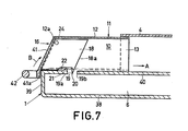
- Fig. 7 shows a housing in the form of a storage case for gramophone records, which housing has a construction derived from that of the first embodiment, corresponding parts bearing the same reference numerals as in Figs. 1 to 3.
- the housing 1 comprises a bottom wall 38 which is integral with the upright side walls 6, a rear wall and a front wall 39, and the fixed cover 4.
- On the inner surface of each side wall 6 a ridge 40 is formed, which ridge extends parallel with the bottom wall 38 and has a small width measured at right angles to the plane of the side wall 6.
- the side portions of the sliding section 11 and the front section 16 of the dust cover 10 are slidable on the ridges 40.
- each ridge 40 a guide slot 19 is formed, which slot is open to one side and has ends 19a and 19b. At the end 19a of each slot a tilting projection 21 is formed on the upper side of the respective ridge 40.
- the front section 16 comprises a central front portion 41 of which a part 41a extends over a part of the front wall 39 of the housing when the front section is in the closed position.
- the part 41a is formed with a grip 42 by means of which the housing can be lifted and carried about when the front section 16 is in the closed position.
- the grip 42 has the same function in opening and closing the dust cover 10 as the grip 23 in the first embodiment.
- the grip 42 may be used for opening the cover and after the dust cover has been closed this grip 42 may be used for lifting the housing.
- the front section 16 is latched to the housing 1 in its closed position in a manner not shown, for example near the grip 42, in order to avoid an unfavourable loading of the dust cover 10 when the housing is lifted.
- the ridges 40 occupy only a minimal space in the housing and therefore do not impede the storage of the items to be stored.
- the present embodiment is particularly suitable for the convenient and dust-tight storage and transport of various types of article such as gramophone records, documents etc.
- housing 1 with the dust cover 10 shown in Figs. 4-6 may also be used as a storage case in a manner not shown but similar to that shown in Fig. 7.
- This has the additional advantage that the dust cover 10 can be slid over the fixed cover 29, so that sliding can be effected over the outside of the housing.
Landscapes
- Casings For Electric Apparatus (AREA)
Applications Claiming Priority (2)
| Application Number | Priority Date | Filing Date | Title |
|---|---|---|---|
| NL8301365 | 1983-04-19 | ||
| NL8301365 | 1983-04-19 |
Publications (2)
| Publication Number | Publication Date |
|---|---|
| EP0125712A1 true EP0125712A1 (fr) | 1984-11-21 |
| EP0125712B1 EP0125712B1 (fr) | 1987-08-19 |
Family
ID=19841726
Family Applications (1)
| Application Number | Title | Priority Date | Filing Date |
|---|---|---|---|
| EP84200517A Expired EP0125712B1 (fr) | 1983-04-19 | 1984-04-12 | Bâti, tel que coffret d'un tourne-disques, avec un couvercle de protection fermant la face supérieure du bâti |
Country Status (5)
| Country | Link |
|---|---|
| US (1) | US4600247A (fr) |
| EP (1) | EP0125712B1 (fr) |
| JP (1) | JPS59223901A (fr) |
| CA (1) | CA1217225A (fr) |
| DE (1) | DE3465535D1 (fr) |
Families Citing this family (4)
| Publication number | Priority date | Publication date | Assignee | Title |
|---|---|---|---|---|
| NL8403117A (nl) * | 1984-10-12 | 1986-05-01 | Philips Nv | Platenspeler. |
| US4709972A (en) * | 1986-08-27 | 1987-12-01 | Eastman Kodak Company | Keyboard cabinet with sliding tray |
| JP3427642B2 (ja) * | 1996-11-08 | 2003-07-22 | ティアック株式会社 | ディスク装置 |
| US6112465A (en) * | 1999-08-24 | 2000-09-05 | Wang; Shou-Nian | Door device for an electric discharging machine |
Citations (7)
| Publication number | Priority date | Publication date | Assignee | Title |
|---|---|---|---|---|
| DE903140C (de) * | 1951-11-29 | 1954-02-01 | Schwaebische Formholz Ges M B | Plattenspielergehaeuse mit feststehendem Laufwerkboden |
| DE1207656B (de) * | 1963-08-30 | 1965-12-23 | Telefunken Patent | Plattenspieler mit Gehaeuse und Deckel |
| US3268285A (en) * | 1964-10-07 | 1966-08-23 | Wells Gardner Electronics | Sliding panel assembly |
| GB1132025A (en) * | 1966-02-18 | 1968-10-30 | Ball Office Equipment Ltd | Improvements in or relating to dispensers for sheet material |
| FR93516E (fr) * | 1967-05-30 | 1969-04-11 | Catelas Claude | Boite de classement. |
| US3549224A (en) * | 1968-07-17 | 1970-12-22 | British Ind Corp | Phonograph base and dust cover therefor |
| DE2146846A1 (de) * | 1971-09-20 | 1973-03-29 | Papst Motoren Kg | Kassettengeraet |
Family Cites Families (2)
| Publication number | Priority date | Publication date | Assignee | Title |
|---|---|---|---|---|
| US1330301A (en) * | 1916-05-22 | 1920-02-10 | Henry C Brown | Filing-cabinet for talking-machine records |
| US3782801A (en) * | 1972-09-11 | 1974-01-01 | Dual Gebrueder Steidinger | Console for record players |
-
1984
- 1984-04-11 US US06/599,040 patent/US4600247A/en not_active Expired - Fee Related
- 1984-04-12 EP EP84200517A patent/EP0125712B1/fr not_active Expired
- 1984-04-12 DE DE8484200517T patent/DE3465535D1/de not_active Expired
- 1984-04-19 CA CA000452520A patent/CA1217225A/fr not_active Expired
- 1984-04-19 JP JP59079312A patent/JPS59223901A/ja active Pending
Patent Citations (7)
| Publication number | Priority date | Publication date | Assignee | Title |
|---|---|---|---|---|
| DE903140C (de) * | 1951-11-29 | 1954-02-01 | Schwaebische Formholz Ges M B | Plattenspielergehaeuse mit feststehendem Laufwerkboden |
| DE1207656B (de) * | 1963-08-30 | 1965-12-23 | Telefunken Patent | Plattenspieler mit Gehaeuse und Deckel |
| US3268285A (en) * | 1964-10-07 | 1966-08-23 | Wells Gardner Electronics | Sliding panel assembly |
| GB1132025A (en) * | 1966-02-18 | 1968-10-30 | Ball Office Equipment Ltd | Improvements in or relating to dispensers for sheet material |
| FR93516E (fr) * | 1967-05-30 | 1969-04-11 | Catelas Claude | Boite de classement. |
| US3549224A (en) * | 1968-07-17 | 1970-12-22 | British Ind Corp | Phonograph base and dust cover therefor |
| DE2146846A1 (de) * | 1971-09-20 | 1973-03-29 | Papst Motoren Kg | Kassettengeraet |
Also Published As
| Publication number | Publication date |
|---|---|
| CA1217225A (fr) | 1987-01-27 |
| US4600247A (en) | 1986-07-15 |
| DE3465535D1 (en) | 1987-09-24 |
| EP0125712B1 (fr) | 1987-08-19 |
| JPS59223901A (ja) | 1984-12-15 |
Similar Documents
| Publication | Publication Date | Title |
|---|---|---|
| KR0156949B1 (ko) | 공구 파렛을 지니는 공구상자 | |
| US5097946A (en) | Storage unit for compact discs and the like | |
| IE53812B1 (en) | Tape cassette | |
| US4285557A (en) | Storage tray for packaged articles | |
| US5411134A (en) | Container for compact disks and the like | |
| US2785036A (en) | Cabinets | |
| GB2249473A (en) | Storage box for compact discs | |
| US4320852A (en) | Mobile file lid | |
| EP0180273B1 (fr) | Appareil pour l'enregistrement et/ou la reproduction de signaux | |
| EP0125712B1 (fr) | Bâti, tel que coffret d'un tourne-disques, avec un couvercle de protection fermant la face supérieure du bâti | |
| GB2191470A (en) | A box for thin objects | |
| GB1520999A (en) | Cassette tape recorders | |
| CA1042394A (fr) | Receptacle pour cassette de bande magnetique | |
| US5517478A (en) | Disc player for performing disc loading and ejecting in response to opening and closing of lid | |
| US3549224A (en) | Phonograph base and dust cover therefor | |
| GB2077234A (en) | Storage container for tape cassettes | |
| US5068758A (en) | Cassette loading device for a tape recorder | |
| CA1186963A (fr) | Systeme de rangement | |
| GB2096229A (en) | Anti-tilt arrangement for multi- drawer cabinet | |
| EP0238752A1 (fr) | Magasin pour unités de stockage de données en combinaison avec appareil d'écriture/lecture destiné à reçevoir le dit magasin | |
| US5502608A (en) | Tape cassette | |
| EP0666564B1 (fr) | Cassette à bande | |
| JPH0230982Y2 (fr) | ||
| CN222634907U (zh) | 具有湿度可控的容器的冷却装置 | |
| EP0971325A2 (fr) | Appareil de distribution d'articles ayant une excellente capacité de stockage et permettant une réduction de la surface d'installation |
Legal Events
| Date | Code | Title | Description |
|---|---|---|---|
| PUAI | Public reference made under article 153(3) epc to a published international application that has entered the european phase |
Free format text: ORIGINAL CODE: 0009012 |
|
| AK | Designated contracting states |
Designated state(s): CH DE FR GB IT LI |
|
| 17P | Request for examination filed |
Effective date: 19841224 |
|
| 17Q | First examination report despatched |
Effective date: 19861022 |
|
| GRAA | (expected) grant |
Free format text: ORIGINAL CODE: 0009210 |
|
| AK | Designated contracting states |
Kind code of ref document: B1 Designated state(s): CH DE FR GB IT LI |
|
| REF | Corresponds to: |
Ref document number: 3465535 Country of ref document: DE Date of ref document: 19870924 |
|
| ITF | It: translation for a ep patent filed | ||
| ET | Fr: translation filed | ||
| PLBE | No opposition filed within time limit |
Free format text: ORIGINAL CODE: 0009261 |
|
| STAA | Information on the status of an ep patent application or granted ep patent |
Free format text: STATUS: NO OPPOSITION FILED WITHIN TIME LIMIT |
|
| 26N | No opposition filed | ||
| PG25 | Lapsed in a contracting state [announced via postgrant information from national office to epo] |
Ref country code: LI Effective date: 19890430 Ref country code: CH Effective date: 19890430 |
|
| REG | Reference to a national code |
Ref country code: CH Ref legal event code: PL |
|
| PGFP | Annual fee paid to national office [announced via postgrant information from national office to epo] |
Ref country code: DE Payment date: 19900622 Year of fee payment: 7 |
|
| PGFP | Annual fee paid to national office [announced via postgrant information from national office to epo] |
Ref country code: GB Payment date: 19910402 Year of fee payment: 8 |
|
| PGFP | Annual fee paid to national office [announced via postgrant information from national office to epo] |
Ref country code: FR Payment date: 19910419 Year of fee payment: 8 |
|
| PG25 | Lapsed in a contracting state [announced via postgrant information from national office to epo] |
Ref country code: DE Effective date: 19920201 |
|
| PG25 | Lapsed in a contracting state [announced via postgrant information from national office to epo] |
Ref country code: GB Effective date: 19920412 |
|
| GBPC | Gb: european patent ceased through non-payment of renewal fee | ||
| PG25 | Lapsed in a contracting state [announced via postgrant information from national office to epo] |
Ref country code: FR Effective date: 19921230 |
|
| REG | Reference to a national code |
Ref country code: FR Ref legal event code: ST |