EP0125719A1 - Presse à balles rondes - Google Patents
Presse à balles rondes Download PDFInfo
- Publication number
- EP0125719A1 EP0125719A1 EP84200634A EP84200634A EP0125719A1 EP 0125719 A1 EP0125719 A1 EP 0125719A1 EP 84200634 A EP84200634 A EP 84200634A EP 84200634 A EP84200634 A EP 84200634A EP 0125719 A1 EP0125719 A1 EP 0125719A1
- Authority
- EP
- European Patent Office
- Prior art keywords
- belt
- crop
- members
- elements
- supporting
- Prior art date
- Legal status (The legal status is an assumption and is not a legal conclusion. Google has not performed a legal analysis and makes no representation as to the accuracy of the status listed.)
- Granted
Links
Images

Classifications
-
- A—HUMAN NECESSITIES
- A01—AGRICULTURE; FORESTRY; ANIMAL HUSBANDRY; HUNTING; TRAPPING; FISHING
- A01F—PROCESSING OF HARVESTED PRODUCE; HAY OR STRAW PRESSES; DEVICES FOR STORING AGRICULTURAL OR HORTICULTURAL PRODUCE
- A01F15/00—Baling presses for straw, hay or the like
- A01F15/07—Rotobalers, i.e. machines for forming cylindrical bales by winding and pressing
-
- A—HUMAN NECESSITIES
- A01—AGRICULTURE; FORESTRY; ANIMAL HUSBANDRY; HUNTING; TRAPPING; FISHING
- A01F—PROCESSING OF HARVESTED PRODUCE; HAY OR STRAW PRESSES; DEVICES FOR STORING AGRICULTURAL OR HORTICULTURAL PRODUCE
- A01F15/00—Baling presses for straw, hay or the like
- A01F15/07—Rotobalers, i.e. machines for forming cylindrical bales by winding and pressing
- A01F2015/078—Pressing chamber formed exclusively by flexible elements, e.g. belts
-
- A—HUMAN NECESSITIES
- A01—AGRICULTURE; FORESTRY; ANIMAL HUSBANDRY; HUNTING; TRAPPING; FISHING
- A01F—PROCESSING OF HARVESTED PRODUCE; HAY OR STRAW PRESSES; DEVICES FOR STORING AGRICULTURAL OR HORTICULTURAL PRODUCE
- A01F15/00—Baling presses for straw, hay or the like
- A01F15/07—Rotobalers, i.e. machines for forming cylindrical bales by winding and pressing
- A01F2015/0795—Pressing chamber with variable volume
-
- A—HUMAN NECESSITIES
- A01—AGRICULTURE; FORESTRY; ANIMAL HUSBANDRY; HUNTING; TRAPPING; FISHING
- A01F—PROCESSING OF HARVESTED PRODUCE; HAY OR STRAW PRESSES; DEVICES FOR STORING AGRICULTURAL OR HORTICULTURAL PRODUCE
- A01F15/00—Baling presses for straw, hay or the like
- A01F15/08—Details
- A01F15/18—Endless belts, rolls or the like
- A01F2015/183—Constructional details of belts of the press chamber
Definitions
- the invention relates to a device for form crop lying on the field into round bales, said device mainly comprising a frame movable across the field and having to relatively spaced walls, a group of guiding and stretching members arranged between and supported by said walls for guiding ans maintaining the tension of one or more endless, belt-like elements and means for picking-up the crop from the ground.
- a device of the kind set forth in the preamble delivers cylindrical bales in which the crop is compressed to a greater or lesser extent in dependence on the type of device i.e. a device in which the crop is compressed from the beginning whilst being wound or a device in which the compression of the crop takes place at the end of the winding operation.
- a disadvantage of the first-mentioned type of device is that the rolling belts which have to yield to the increasing diameter of the bale may be overloaded by excessive supply of crop so rupture of a belt may occur.
- the second type mentioned above has the inconvenience that the core of the bale os not rolled over, but irregularly compressed so that the crop cannot be satisfactorily distributed for consumption.
- the invention has for its object to obviate the aforesaid disadvantages and provides to this end a device which is distinguished in that a group of supporting members connected with a wall is arranged inside the space bounded by an endless belt element, which supporting members are disposed in a circle.
- the endless belt-like element is urged against the supporting members at a given volume of received crop so that the yielding movement of the belt-like element is limited and rupture of the belt is avoided. Nevertheless right from the beginning of the bale formation the core of the bale is exerted to pressure so that the bale has a uniform density throughout its volume.
- the device proposed by the invention can be readily adapted to the desired bale size, which depends on the kind of crop to be compressed.
- At least two belt-like elements are arranged between the walls, whose proximal active parts are converging at an angle to and away from the pick-up means.
- the space formed between the active parts is small and the crop fed into said space will be subjected from the beginning to sufficient pressure during rolling of the crop.
- the invention proposes to pass the active parts of the two belt-like elements in between a pair of guide members arranged on a holder away from and towards the pick-up means. In this way during rolling of the crop the belts can be urged by higher pressure against the crop which is conducive to the compression of the crop.
- the frame with a pivotable part for releasing the formed bale after being tied up or packed.
- this pivotable part one of the belt-like elements is supported.
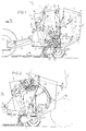
- the device illuminated in the figures mainly comprises a frame 2 which is movable in the direction of the arrow P1 on ground wheels 1 across the field.
- the frame may be coupled through a drawbar 3 with an agricultural tractor 4, only the rear wheel of which is shown schematically.
- the device is driven through the power take-off shaft and the auxiliary shaft 5, which will be set out in detail hereinafter.
- the frame 2 may be constructed in any way and mainly comprises two parallel, vertical walls 6 spaced apart by a distance such that an endless, belt-like element (see fig. 4 or 5) can operate between them.
- two endless belt-like elements 7 and 8 are arranged, each of which is passed around its own system of supporting rollers 9 and stretching rollers 10.
- the supporting rollers 9 are directly journalled on the inner side of the walls 6 and are, therefore, not dispaceable with respect thereto.
- the stretching rollers 10 are each arranged on an arm 11, the other end of which is fastened to a spindle 12 journalled in the wall 6 and having fastened to it a lever arm 13.
- the free end of the lever arm 13 is coupled with a cylinder 14 supported by the wall 6.
- the lever arm 13 with the associated cylinder 14 may be arranged on the outer side or the inner side respectively of the wall.
- the proximal runs of the belts 7 and 8 are passed between a pair of guide members 15, which are journalled on a common carrier 16 on on each side thereof and on the inner sides of the walls 6.
- the common carrier 16 is connected by a parallel guide 17 with the inner side ⁇ f the wall 6, whilst one of the pivotal shafts 18 of the parallel rods 17 is provided with a lever arm 19, the free end of which cooperates with a cylinder 20 supported by a side wall 6.
- a pick-up member is formed by a rotating pick-up mechanism 21 by which the crop 22 lying on the ground can be picked up.
- two supporting rollers 22 are obliquely arranged for supporting the picked up crop.
- roller 23 is arranged below the belt run 7 so as to be rotatably drivable in the direction of the arrow P4.
- An essential feature of the invention is that a group of supporting rollers 24 is arranged in a circular configuration inside the walls 6 and also in the space bounded by the endless, belt-like elements 7 and 8.
- the supporting members 24 may be designed in any way and they serve to limit the maximum yielding movement of the belt runs 7 and 8, which is explained further with reference to figs. 2 and 3.
- the frame is constructed so that its rear part can be tilted up, which rear part is formed by wall parts 6' pivotable about a horizontal pivotal shaft 25.
- the pivotal shaft 25 coincides with one of the rotary axes of the guide rollers 9 of the belt-like elements 8.
- a hydraulic ram 26 is provided, the upper end part of which is pivotally connected with the tiltable part 6', whereas the lower end is fastened to an arm 28 which is pivotable about a stub shaft 27 and the free end of which actuates a pressure pin 29, which is slidably fastened to the outer side of the fixed wall 6.
- the lower end of the pin 29 bears on the nose-shaped end part of a lock bolt 30, which is pivotally connected with the movable wall part 6'.
- the recess in the lock bolt 30 snaps around a locking pin 31 in the fixed wall part 6 by the tension of the spring 32.
- the locking mechanism may be provided on one side or on both sides of the device.
- the device described above operates as follows: When the device is moved in the direction of the arrow P1 across the field the pick-up means 21 can pick up the crop 22 and feed it into a space by the lower parts of the proximal runs of the belt-like elements 7, 8, the roller 23 and finally the supporting rollers 22 (see fig. 1). It appears that owing to the low position of the guide members 15 the space above the supporting rollers 22 is relatively small so that the core of the bale to be formed is compressed already in an early stage. The required rolling effect is obtained by driving the belt-like element 7 or 8 respectively in the direction of the arrow P2 or P3 respectively so that the crop is rolled up in anti-clockwise direction. The roller 23 ensures that no crop will be carried along by the lower run of the belt 7.
- the belt runs will diverge from one enother becaise more space is required to receive more crop. Therefore, the stretching rollers 10 tend to move inwards, which is counteracted by the associated cylinders 14. Also in this manner the wall remains sufficiently taut.
- the end position is attained as shown in fig. 2, from which it is apparent that a roll of a diameter corresponding with the inscribed circle of the supporting rollers 24 is formed.
- the rear part 6' can be tilted up by actuating the cylinder 26, which initially turns downwards the lever 28, which urges the pin 29 downwards and releases the latch 30.
- the rear part 6' is turned upwards into the position indicated by the broken line in fig. 2
- the ready bale is indicated by the broken line 33.
- Fig. 3 illustrates the situation in which the supporting rollers 24 are arranged on a circle of smaller diameter. This results in a bale 33' whose diameter is considerably smaller than that in fig. 2.
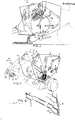
- Figs. 4 and 5 show the course of the belt; in fig. 4 the belt-like element is formed by a ladder belt. It comprises two relatively spaced, parallel toothed belts 35 between which rods 36 are fastened (see also fig. 6).
- the shape of the rods may be arbitrary and in the embodiment shown the rod is formed by a tube flattened at both ends to form fastening tags 37. By means of bolts, nails or other material the rods 36 can be secured to the belt 35.
- the fixed guide or stretching members are formed here by wheel-shaped elements along which the toothed belt 35 is passed. Thus construction reduces the risk of crop winding around the guide or stretching elements.
- Fig. 5 shows that the belt-like element is formed by a plurality of parallel ropes and the guide or stretching members are formed by rollers journalled between the walls 6 and the arms 11 respectively.
- Fig. 7 schematically shows the drive through the auxiliary shaft 5 from the agricultural tractor.
- the auxiliary shaft 5 drives a transmission in a casing 40, the output shaft 41 of which is transverse of the transport direction P1.
- At the end of the output shaft are arranged three driving discs 42, the outermost disc being coupled through an endless element 43 with a driving disc 44, the rotary axis of which coincides with one of the fixed guide members 9 of the belt 7.
- a pressure disc 45 is provided to ensure slip-free transmission between the driving roller 9 and the belt 7.
- the second disc 42 is connected through a flexible, endless element 46 with a disc 47, which is fastened to the rotary shaft of a fixed roller 9 of the belt-like element 8.
- the third disc is connected through a flexible element 48 with a disc 49, by which the rollers 22 or the pick-up means 21 respectively can be driven.
- the two belt-like elements 7, 8 may be united to form a single belt-like element, provided the parts of the pick-up means bounding the roll space for the bale to be formed converge to the rear.
- the discharge of the bale by tilting up the rear part 6' may be performed in a different way, for example, about a vertical pivotal shaft without falling beyond the scope of the invention i.e. the disposition of the supporting rollers 24.
- the construction of the belt-like elements 7, 8 may be chosen arbitrarily, for example, there may be conceived a continuous belt whose width corresponds to the distance between the sidewalls.
Landscapes
- Life Sciences & Earth Sciences (AREA)
- Environmental Sciences (AREA)
- Storage Of Harvested Produce (AREA)
- Apparatuses For Bulk Treatment Of Fruits And Vegetables And Apparatuses For Preparing Feeds (AREA)
- Formation And Processing Of Food Products (AREA)
- Basic Packing Technique (AREA)
Applications Claiming Priority (2)
| Application Number | Priority Date | Filing Date | Title |
|---|---|---|---|
| NL8301647 | 1983-05-09 | ||
| NL8301647A NL8301647A (nl) | 1983-05-09 | 1983-05-09 | Inrichting voor het tot een ronde baal vormen van gewas. |
Publications (2)
| Publication Number | Publication Date |
|---|---|
| EP0125719A1 true EP0125719A1 (fr) | 1984-11-21 |
| EP0125719B1 EP0125719B1 (fr) | 1989-09-06 |
Family
ID=19841830
Family Applications (1)
| Application Number | Title | Priority Date | Filing Date |
|---|---|---|---|
| EP84200634A Expired EP0125719B1 (fr) | 1983-05-09 | 1984-05-03 | Presse à balles rondes |
Country Status (9)
| Country | Link |
|---|---|
| US (1) | US4550557A (fr) |
| EP (1) | EP0125719B1 (fr) |
| JP (1) | JPS6037917A (fr) |
| BR (1) | BR8402258A (fr) |
| DE (1) | DE3479629D1 (fr) |
| DK (1) | DK225484A (fr) |
| ES (1) | ES8502836A1 (fr) |
| NL (1) | NL8301647A (fr) |
| YU (1) | YU80384A (fr) |
Cited By (10)
| Publication number | Priority date | Publication date | Assignee | Title |
|---|---|---|---|---|
| US4707974A (en) * | 1985-12-23 | 1987-11-24 | Vermeer Manufacturing Co. | Method and apparatus for reducing entrapment of a crop material in a round crop baler |
| GB2210824A (en) * | 1987-10-09 | 1989-06-21 | Welger Gebr Gmbh & Co Kg | Pick-up roll baler |
| EP0331872A3 (en) * | 1988-02-23 | 1990-01-17 | P.J. Zweegers En Zonen Landbouwmachinefabriek B.V. | Rotobaler |
| EP0259244B1 (fr) * | 1986-09-04 | 1991-10-23 | The Goodyear Tire & Rubber Company | Convoyeur pour moissonneuse-batteuse |
| EP0235787B1 (fr) * | 1986-03-05 | 1992-05-27 | Deere & Company | Machine pour former des balles cylindriques |
| FR2767635A1 (fr) * | 1997-09-03 | 1999-03-05 | Proofunique France Sa | Presse a balles a chambre variable pour des produits agricoles tels que de la paille ou du fourrage |
| EP0970598A1 (fr) | 1998-07-09 | 2000-01-12 | Kverneland Geldrop B.V. | Presse à balles rondes |
| US6079324A (en) * | 1995-07-24 | 2000-06-27 | Antonio Feraboli | Variable chamber round baler having a bale core formation chamber with a variable geometry |
| CN100544581C (zh) * | 2007-09-28 | 2009-09-30 | 牛广华 | 方草压捆机 |
| WO2012069225A1 (fr) | 2010-11-26 | 2012-05-31 | Contitech Transportbandsysteme Gmbh | Bande de presse sans fin à balles rondes, en caoutchouc ou matières semblables au caoutchouc |
Families Citing this family (16)
| Publication number | Priority date | Publication date | Assignee | Title |
|---|---|---|---|---|
| US4658573A (en) * | 1985-04-08 | 1987-04-21 | New Holland Inc. | Signal device for bale forming machine |
| JPS61254123A (ja) * | 1985-05-02 | 1986-11-11 | 高北農機株式会社 | ロ−ルベ−ラ− |
| JPS6331753U (fr) * | 1986-08-19 | 1988-03-01 | ||
| US5044272A (en) * | 1987-06-18 | 1991-09-03 | Ford New Holland, Inc. | Round baler with rollers and belts |
| DE4012753C2 (de) * | 1990-04-21 | 1993-12-16 | Krone Bernhard Gmbh Maschf | Maschine zum Aufnehmen und Pressen von landwirtschaftlichem Erntegut |
| DE4215308C2 (de) * | 1992-05-09 | 1995-11-30 | Deere & Co | Rundballenpresse |
| DE102004023696B4 (de) * | 2004-05-11 | 2007-03-29 | Maschinenfabrik Bernard Krone Gmbh | Maschine zum Aufnehmen und Pressen von landwirtschaftlichem Erntegut |
| DE102004023705B3 (de) * | 2004-05-11 | 2005-10-06 | Maschinenfabrik Bernard Krone Gmbh | Maschine zum Aufnehmen und Pressen von landwirtschaftlichem Erntegut |
| DE102004023704B4 (de) * | 2004-05-11 | 2006-10-19 | Maschinenfabrik Bernard Krone Gmbh | Maschine zum Aufnehmen und Pressen von landwirtschaftlichem Erntegut |
| DE102004023694B4 (de) * | 2004-05-11 | 2007-03-29 | Maschinenfabrik Bernard Krone Gmbh | Maschine zum Aufnehmen und Pressen von landwirtschaftlichem Erntegut |
| DE102016002144A1 (de) * | 2016-02-25 | 2017-08-31 | Maschinenfabrik Krone Beteiligungs-GmbH | Fördergurt und landwirtschaftliche Erntemaschinen mit einem Fördergurt |
| CN108974498A (zh) * | 2017-05-31 | 2018-12-11 | 湖南千山制药机械股份有限公司 | 一种持续带压压缩成捆装置 |
| US11109536B2 (en) | 2017-08-14 | 2021-09-07 | Deere & Company | Split roller configuration for a round module builder or round baler |
| CN115067086B (zh) * | 2022-07-04 | 2024-04-16 | 呼伦贝尔市海征机械制造有限责任公司 | 一种捆草机打包装置 |
| US12274209B1 (en) * | 2024-06-21 | 2025-04-15 | Jiangsu University | Baling mechanism of cotton picker and control system of baling mechanism |
| CN121180535A (zh) * | 2024-06-21 | 2025-12-23 | 江苏大学 | 一种采棉机打包机构及其控制系统 |
Citations (4)
| Publication number | Priority date | Publication date | Assignee | Title |
|---|---|---|---|---|
| US2627223A (en) * | 1949-08-08 | 1953-02-03 | Howard J Berge | Baling machine for compacting straw and stalks from harvesting machines into cylindrical bales |
| US4121513A (en) * | 1976-07-12 | 1978-10-24 | Kopaska Arnold F | Machine for rolling crops into round bales |
| EP0037155A1 (fr) * | 1980-04-02 | 1981-10-07 | Sperry Corporation | Presse à balles cylindriques |
| GB2090560A (en) * | 1980-12-09 | 1982-07-14 | Brockdale Developments Ltd | Agricultural baling machine |
Family Cites Families (11)
| Publication number | Priority date | Publication date | Assignee | Title |
|---|---|---|---|---|
| US3894484A (en) * | 1974-07-17 | 1975-07-15 | Deere & Co | Bale wrapping mechanism for large cylindrical bales |
| US3895573A (en) * | 1974-09-16 | 1975-07-22 | Int Harvester Co | Cylindrical bale forming system |
| US4386493A (en) * | 1975-06-09 | 1983-06-07 | Hesston Corporation | Method and apparatus for making large round crop bales |
| US3992987A (en) * | 1975-08-25 | 1976-11-23 | Sereg Joseph F | Belt guide roller for balers |
| US4172354A (en) * | 1977-01-28 | 1979-10-30 | Vermeer Manufacturing Company | Machine for forming large round bales of crop material |
| US4198804A (en) * | 1978-08-08 | 1980-04-22 | Gebr. Claas Maschinenfabrik Gmbh | Round baler machine |
| US4252057A (en) * | 1979-06-04 | 1981-02-24 | Hesston Corporation | Bale tensioning apparatus in a rotary baler |
| US4258619A (en) * | 1979-06-28 | 1981-03-31 | Hesston Corporation | Rotary baler having bale-ejecting apparatus |
| US4339907A (en) * | 1980-11-24 | 1982-07-20 | Kopaska Arnold F | Endless belt changing in a rotary crop baler |
| US4391187A (en) * | 1981-10-05 | 1983-07-05 | Deere & Company | Belt-tensioning system for round balers |
| US4470247A (en) * | 1983-05-25 | 1984-09-11 | Sperry Corporation | Round bale forming machine |
-
1983
- 1983-05-09 NL NL8301647A patent/NL8301647A/nl not_active Application Discontinuation
-
1984
- 1984-05-02 US US06/606,246 patent/US4550557A/en not_active Expired - Fee Related
- 1984-05-03 DE DE8484200634T patent/DE3479629D1/de not_active Expired
- 1984-05-03 EP EP84200634A patent/EP0125719B1/fr not_active Expired
- 1984-05-07 DK DK225484A patent/DK225484A/da not_active Application Discontinuation
- 1984-05-08 ES ES532289A patent/ES8502836A1/es not_active Expired
- 1984-05-08 YU YU00803/84A patent/YU80384A/xx unknown
- 1984-05-09 JP JP59091167A patent/JPS6037917A/ja active Pending
- 1984-11-09 BR BR8402258A patent/BR8402258A/pt unknown
Patent Citations (4)
| Publication number | Priority date | Publication date | Assignee | Title |
|---|---|---|---|---|
| US2627223A (en) * | 1949-08-08 | 1953-02-03 | Howard J Berge | Baling machine for compacting straw and stalks from harvesting machines into cylindrical bales |
| US4121513A (en) * | 1976-07-12 | 1978-10-24 | Kopaska Arnold F | Machine for rolling crops into round bales |
| EP0037155A1 (fr) * | 1980-04-02 | 1981-10-07 | Sperry Corporation | Presse à balles cylindriques |
| GB2090560A (en) * | 1980-12-09 | 1982-07-14 | Brockdale Developments Ltd | Agricultural baling machine |
Cited By (12)
| Publication number | Priority date | Publication date | Assignee | Title |
|---|---|---|---|---|
| US4707974A (en) * | 1985-12-23 | 1987-11-24 | Vermeer Manufacturing Co. | Method and apparatus for reducing entrapment of a crop material in a round crop baler |
| EP0235787B1 (fr) * | 1986-03-05 | 1992-05-27 | Deere & Company | Machine pour former des balles cylindriques |
| EP0259244B1 (fr) * | 1986-09-04 | 1991-10-23 | The Goodyear Tire & Rubber Company | Convoyeur pour moissonneuse-batteuse |
| GB2210824A (en) * | 1987-10-09 | 1989-06-21 | Welger Gebr Gmbh & Co Kg | Pick-up roll baler |
| GB2210824B (en) * | 1987-10-09 | 1992-01-02 | Welger Gebr Gmbh & Co Kg | Pick-up roll baler |
| EP0331872A3 (en) * | 1988-02-23 | 1990-01-17 | P.J. Zweegers En Zonen Landbouwmachinefabriek B.V. | Rotobaler |
| US6079324A (en) * | 1995-07-24 | 2000-06-27 | Antonio Feraboli | Variable chamber round baler having a bale core formation chamber with a variable geometry |
| FR2767635A1 (fr) * | 1997-09-03 | 1999-03-05 | Proofunique France Sa | Presse a balles a chambre variable pour des produits agricoles tels que de la paille ou du fourrage |
| EP0970598A1 (fr) | 1998-07-09 | 2000-01-12 | Kverneland Geldrop B.V. | Presse à balles rondes |
| CN100544581C (zh) * | 2007-09-28 | 2009-09-30 | 牛广华 | 方草压捆机 |
| WO2012069225A1 (fr) | 2010-11-26 | 2012-05-31 | Contitech Transportbandsysteme Gmbh | Bande de presse sans fin à balles rondes, en caoutchouc ou matières semblables au caoutchouc |
| DE102010060828A1 (de) | 2010-11-26 | 2012-05-31 | Contitech Transportbandsysteme Gmbh | Endloses Rundballenpressband aus Gummi oder gummiähnlichen Stoffen |
Also Published As
| Publication number | Publication date |
|---|---|
| ES532289A0 (es) | 1985-02-01 |
| YU80384A (en) | 1987-10-31 |
| DE3479629D1 (en) | 1989-10-12 |
| DK225484D0 (da) | 1984-05-07 |
| US4550557A (en) | 1985-11-05 |
| ES8502836A1 (es) | 1985-02-01 |
| NL8301647A (nl) | 1984-12-03 |
| EP0125719B1 (fr) | 1989-09-06 |
| JPS6037917A (ja) | 1985-02-27 |
| DK225484A (da) | 1984-11-10 |
| BR8402258A (pt) | 1984-12-18 |
Similar Documents
| Publication | Publication Date | Title |
|---|---|---|
| EP0125719B1 (fr) | Presse à balles rondes | |
| US3964246A (en) | Rotary baler | |
| US4789289A (en) | Bale loader, handler and feeder | |
| US4731984A (en) | Balers | |
| US3901007A (en) | Hay roll forming machine | |
| US4212149A (en) | Crop baling machines | |
| US5009062A (en) | Baling apparatus | |
| US4803832A (en) | Method and apparatus for forming bales | |
| CA1322695C (fr) | Ramasseuse-botteleuse formant des bottes de fourrage cylindriques | |
| US3859909A (en) | Hay roll forming machine | |
| CA1284057C (fr) | Methode et dispositif pour produire des balles cylindriques d'un produit agricole a l'aide d'une lieuse sur camion | |
| US4288971A (en) | Round baler | |
| US4169347A (en) | Belt-type baler for cylindrical bales | |
| IE52219B1 (en) | Agricultural machine for forming a round bale | |
| EP3593627A1 (fr) | Mécanisme de tension constante de nouage de filet pour ramasseuses-enrouleuses | |
| US3792574A (en) | Hay rolling machine with compressing means | |
| GB2210824A (en) | Pick-up roll baler | |
| US3939631A (en) | Hay roll forming machine | |
| US4184426A (en) | Baling device for agricultural crops | |
| US3827223A (en) | Hay roll forming machine | |
| WO1994027423A1 (fr) | Machine d'emballage de bales de fourrage | |
| US3848526A (en) | Hay roll forming machine | |
| US4026205A (en) | Hay roll forming machine | |
| HU177636B (en) | Machine for making high size cylindric bales from hay or other harvested stover | |
| US4092818A (en) | Hay baler |
Legal Events
| Date | Code | Title | Description |
|---|---|---|---|
| PUAI | Public reference made under article 153(3) epc to a published international application that has entered the european phase |
Free format text: ORIGINAL CODE: 0009012 |
|
| AK | Designated contracting states |
Designated state(s): BE DE FR GB NL SE |
|
| 17P | Request for examination filed |
Effective date: 19850521 |
|
| 17Q | First examination report despatched |
Effective date: 19860605 |
|
| R17C | First examination report despatched (corrected) |
Effective date: 19870518 |
|
| GRAA | (expected) grant |
Free format text: ORIGINAL CODE: 0009210 |
|
| AK | Designated contracting states |
Kind code of ref document: B1 Designated state(s): BE DE FR GB NL SE |
|
| REF | Corresponds to: |
Ref document number: 3479629 Country of ref document: DE Date of ref document: 19891012 |
|
| ET | Fr: translation filed | ||
| PLBE | No opposition filed within time limit |
Free format text: ORIGINAL CODE: 0009261 |
|
| STAA | Information on the status of an ep patent application or granted ep patent |
Free format text: STATUS: NO OPPOSITION FILED WITHIN TIME LIMIT |
|
| 26N | No opposition filed | ||
| EAL | Se: european patent in force in sweden |
Ref document number: 84200634.8 |
|
| PGFP | Annual fee paid to national office [announced via postgrant information from national office to epo] |
Ref country code: NL Payment date: 19960531 Year of fee payment: 13 |
|
| PGFP | Annual fee paid to national office [announced via postgrant information from national office to epo] |
Ref country code: SE Payment date: 19960604 Year of fee payment: 13 |
|
| PGFP | Annual fee paid to national office [announced via postgrant information from national office to epo] |
Ref country code: BE Payment date: 19960627 Year of fee payment: 13 |
|
| PG25 | Lapsed in a contracting state [announced via postgrant information from national office to epo] |
Ref country code: SE Effective date: 19970504 |
|
| PG25 | Lapsed in a contracting state [announced via postgrant information from national office to epo] |
Ref country code: BE Effective date: 19970531 |
|
| BERE | Be: lapsed |
Owner name: MULTINORM B.V. Effective date: 19970531 |
|
| PG25 | Lapsed in a contracting state [announced via postgrant information from national office to epo] |
Ref country code: NL Effective date: 19971201 |
|
| EUG | Se: european patent has lapsed |
Ref document number: 84200634.8 |
|
| NLV4 | Nl: lapsed or anulled due to non-payment of the annual fee |
Effective date: 19971201 |
|
| PGFP | Annual fee paid to national office [announced via postgrant information from national office to epo] |
Ref country code: DE Payment date: 19990531 Year of fee payment: 16 |
|
| PGFP | Annual fee paid to national office [announced via postgrant information from national office to epo] |
Ref country code: GB Payment date: 19990618 Year of fee payment: 16 |
|
| PG25 | Lapsed in a contracting state [announced via postgrant information from national office to epo] |
Ref country code: GB Free format text: LAPSE BECAUSE OF NON-PAYMENT OF DUE FEES Effective date: 20000503 |
|
| GBPC | Gb: european patent ceased through non-payment of renewal fee |
Effective date: 20000503 |
|
| PG25 | Lapsed in a contracting state [announced via postgrant information from national office to epo] |
Ref country code: DE Free format text: LAPSE BECAUSE OF NON-PAYMENT OF DUE FEES Effective date: 20010301 |
|
| PGFP | Annual fee paid to national office [announced via postgrant information from national office to epo] |
Ref country code: FR Payment date: 20010530 Year of fee payment: 18 |
|
| PG25 | Lapsed in a contracting state [announced via postgrant information from national office to epo] |
Ref country code: FR Free format text: LAPSE BECAUSE OF NON-PAYMENT OF DUE FEES Effective date: 20030131 |
|
| REG | Reference to a national code |
Ref country code: FR Ref legal event code: ST |