EP0125729B1 - Tube d'image en couleurs - Google Patents
Tube d'image en couleurs Download PDFInfo
- Publication number
- EP0125729B1 EP0125729B1 EP84200667A EP84200667A EP0125729B1 EP 0125729 B1 EP0125729 B1 EP 0125729B1 EP 84200667 A EP84200667 A EP 84200667A EP 84200667 A EP84200667 A EP 84200667A EP 0125729 B1 EP0125729 B1 EP 0125729B1
- Authority
- EP
- European Patent Office
- Prior art keywords
- field
- plates
- plane
- electron beams
- shapers
- Prior art date
- Legal status (The legal status is an assumption and is not a legal conclusion. Google has not performed a legal analysis and makes no representation as to the accuracy of the status listed.)
- Expired
Links
- 238000010894 electron beam technology Methods 0.000 claims description 32
- 230000005291 magnetic effect Effects 0.000 claims description 14
- 239000003302 ferromagnetic material Substances 0.000 claims description 6
- OAICVXFJPJFONN-UHFFFAOYSA-N Phosphorus Chemical compound [P] OAICVXFJPJFONN-UHFFFAOYSA-N 0.000 description 6
- 230000002238 attenuated effect Effects 0.000 description 4
- 241000226585 Antennaria plantaginifolia Species 0.000 description 3
- 206010010071 Coma Diseases 0.000 description 3
- XEEYBQQBJWHFJM-UHFFFAOYSA-N Iron Chemical compound [Fe] XEEYBQQBJWHFJM-UHFFFAOYSA-N 0.000 description 2
- PXHVJJICTQNCMI-UHFFFAOYSA-N Nickel Chemical compound [Ni] PXHVJJICTQNCMI-UHFFFAOYSA-N 0.000 description 2
- 239000011521 glass Substances 0.000 description 2
- 238000007689 inspection Methods 0.000 description 2
- 238000004519 manufacturing process Methods 0.000 description 2
- 238000007493 shaping process Methods 0.000 description 2
- 239000000956 alloy Substances 0.000 description 1
- 229910045601 alloy Inorganic materials 0.000 description 1
- 238000001514 detection method Methods 0.000 description 1
- 230000000694 effects Effects 0.000 description 1
- 229910052742 iron Inorganic materials 0.000 description 1
- 239000002184 metal Substances 0.000 description 1
- 229910052751 metal Inorganic materials 0.000 description 1
- 229910052759 nickel Inorganic materials 0.000 description 1
- 238000012216 screening Methods 0.000 description 1
Images


Classifications
-
- H—ELECTRICITY
- H01—ELECTRIC ELEMENTS
- H01J—ELECTRIC DISCHARGE TUBES OR DISCHARGE LAMPS
- H01J31/00—Cathode ray tubes; Electron beam tubes
-
- H—ELECTRICITY
- H01—ELECTRIC ELEMENTS
- H01J—ELECTRIC DISCHARGE TUBES OR DISCHARGE LAMPS
- H01J29/00—Details of cathode-ray tubes or of electron-beam tubes of the types covered by group H01J31/00
- H01J29/46—Arrangements of electrodes and associated parts for generating or controlling the ray or beam, e.g. electron-optical arrangement
- H01J29/56—Arrangements for controlling cross-section of ray or beam; Arrangements for correcting aberration of beam, e.g. due to lenses
-
- H—ELECTRICITY
- H01—ELECTRIC ELEMENTS
- H01J—ELECTRIC DISCHARGE TUBES OR DISCHARGE LAMPS
- H01J29/00—Details of cathode-ray tubes or of electron-beam tubes of the types covered by group H01J31/00
- H01J29/46—Arrangements of electrodes and associated parts for generating or controlling the ray or beam, e.g. electron-optical arrangement
- H01J29/70—Arrangements for deflecting ray or beam
- H01J29/701—Systems for correcting deviation or convergence of a plurality of beams by means of magnetic fields at least
- H01J29/707—Arrangements intimately associated with parts of the gun and co-operating with external magnetic excitation devices
Definitions
- the invention relates to a colour display tube comprising in an evacuated envelope an electron gun system of the "in-line" type for generating three electron beams situated with their axes in one plane, the axis of the central beam coinciding with the tube axis, said electron beams converging on a display screen provided on a wall of the envelope and in an operating display tube being deflected over said display screen in two mutually perpendicular directions by means of a first and a second magnetic deflection field, the direction of the first deflection field being parallel to the said plane, said electron gun system comprising at its end curved field shapers for causing the rasters described on the display screen by the electron beams to substantially coincide, said field shapers facing the electron beams with their concave sides and being opposed to each other such that said plane intersects each one symmetrically, each field shaper comprising at least three plates of ferromagnetic material, at least two of which are arranged circumferentially and define a slot between them, each slot being magnetically bridge
- a display tube having a system of detection coils which is provided with field shaping means.
- the latter consist, for example, of two soft- magnetic elements which are arranged diametrically opposite to each other and substantially transversely to the magnetic field of the frame deflection coil, on the neck side of the system of deflection coils, beyond the line deflection coils.
- a disadvantage of the use of such field-shaping means is that a great part of the frame deflection field is distorted by said means, which consume a comparatively large amount of the deflection energy.
- Another colour display tube is described in EP-A-0 109 717, which concerns prior art under Article 54(3) of the EPC.
- field shapers are supported by the electron gun system.
- the structure of the field shapers described therein makes the first deflection field (the frame deflection field) pincushion-shaped.
- Said pincushion-shaped field comprises substantially a two-pole field having a six-pole component.
- the field also for the rays of the electron beams situated not on the electron beam axes, has the correct strength and shape so that the deflection defocusing of the outermost beams is considerably reduced.
- EP-A-0 109 717 it is described to provide slots in the field shapers and to manufacture said field shapers from two or three circumferentially arranged plates.
- the object is to reduce the losses in the line deflection field (the second deflection field). It is also stated that by providing slots between contiguous plates of the field shapers a field disturbance occurs, which will be described in detail hereinafter with reference to a figure.
- each field shaper comprises at least three plates of ferromagnetic material, at least two of which are arranged circumferentially and define a slot between them, each slot being magnetically bridged on the side remote from the electron beams by the third or further plate(s) radially spaced from said at least two plates.
- the invention is based on the recognition of the fact that if the field shapers are constructed in this manner, a resistance for the second deflection field is created in the field shapers which, however, does not disturb the shape of both the first and the second deflection field and the desired field is obtained.
- each field shaper consists of three plates two plates of which are circumferentially arranged and located symmetrically above and below the said plate and a further, bridging, plate intersects the said plane and is also located symmetrically with respect to the said plane.
- each field shaper from five plates three of which are circumferentially arranged and two of which magnetically bridge the slots between said three plates.
- the various plates are particularly simple to position and to connect when the electron gun system comprises at its end a centering cup in which the circumferentially arranged plates are secured to the inner wall and the bridging plates are secured to the outer wall of the centering cup.
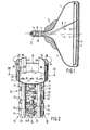
- Figure 1 is a longitudinal sectional view of a colour display tube of the "in-line" type.
- a glass envelope 1 which is composed of a display window 2, a cone 3 and a neck 4, an electron gun system 5 is provided in said neck and generates three electron beams 6, 7, and 8 which are situated with their axes in one plane (the plane of the drawing).
- the axis of the central electron beam 7 before deflection coincides with the tube axis 9.
- the display window 2 comprises on its inside a large number of triplets of phosphor lines. Each triplet comprises a line consisting of a blue-luminescing phosphor, a line consisting of a green luminescing phosphor, and a line consisting of a red-luminescing phosphor.
- the phosphor lines are perpendicular to the plane of the drawing.
- the three electron beams situated in one plane are deflected in the system of deflection coils 13.
- the electron gun system 5 consists of three separate electron guns 14, 15 and 16 as is also shown in Figure 2 in a broken-away elevation.
- the guns 14, 15 and 16 each comprise a control grid or electrode 17 which has an aperture 18.
- a cathode (not visible) for generating the electron beams is provided opposite to said aperture in said control electrode.
- Each gun further comprises a second grid 19, a third grid 20, and a fourth grid 21.
- the grids 17, 19 and 20 are connected to glass rods 23 by means of metal strips 22.
- the grids 21 are connected against the bottom of a common centering cup 24 of non-ferromagnetic material.
- the bottom 25 of the centering cup 24 broken away in this case comprises three apertures 26 through which the electron beams pass.
- Two curved field shapers 27 and 28 each consisting of three curved plates 29, 30, 31 and 32, 33, 34 of ferromagnetic material (for example, an alloy having 58% by weight of nickel and 42% by weight of iron) are provided against the inner wall and the outer wall of the centering cup 24.
- said plates have a length (measured in the direction of the tube axis 9) of approximately 15 mm.
- 2.7 mm wide slots 35 and 36 are provided between the plates 29 and 30 situated side by side in the elongation of each other and between the plates 32 and 33, respectively, which slots, viewed from the tube axis, are overlapped on the outside by the curved plates 31 and 34, respectively 0.25 mm wide slots are present between the plates 29, 30, 32 and 33 on the one hand and the overlapping plates 31 and 34 on the other hand, which slots are filled partly with the cylinder wall of the centering cup 24 consisting of non-ferromagnetic material.
- the diameter of the centering cup 24 is approximately 22 mm.
- the width of the plates 29, 30, 32 and 33 in the flat condition is 8.1 mm and the width of the plates 31 and 34, also in the flat (non-curved) condition, is 5.2 mm.
- Figure 3 is a sectional view through the centering cup 24 of Figure 2.
- the desired extent of pincushion-shaped field distortion of the field parallel to line 37 (the picture field) and possibly also the line deflection field which is perpendicular thereto can be influenced by a suitable choice of the length of the plates 29, 30, 31, 32, 33, 34 measured in the direction of the tube axis and of the angle a of the arc formed for example by the adjacent parallel edges of the plates 29 and 33.
- the field shapers are symmetrical with respect to the plane through the beam axis (the plane of the drawing of Figure 1) and symmetrical with respect to the tube axis 9 which coincides with the axis of the central electron beam prior to deflection.
- the strength of the magnetic shunt can be adjusted by the choice of the thickness of the cylinder wall of the centering cup 24 and the extent of overlap of the plates 31 and 34 on the one hand and the plates 29, 30, 32 and 33 on the other hand.
- FIG. 4a the magnetic field a number of field lines 40 of which are shown is obstructed by the known rings 41 around and beyond the electron beams 42 and 43.
- the desired coma-free field is denoted by a broken line.
- a quadrupole lens action shown in Figure 4c is exerted on the beams which is expressed in a deflection defocusing of the side beams.
- the radial arrows in Figure 4c denote the forces which act on the beams.
- the spots on the display screen shown in Figure 4d become elliptical and are surrounded by a haze.
- the axes of the ellipses in Figure 4d enclose an angle of 45° with the line 37.
- the ellipticity of the spots is the result of an underfocusing.
- the haze areas 48 show in broken lines are the result of overfocusing.
- Figure 5a show a part of the picture field a number of field lines 50 of which are shown.
- Two fields shapers 51 and 52 each consisting of one assembly are placed in said field at the end of the gun and distort the picture field in the desired manner in a pincushion shape.
- Said pincushion shaped field consists substantially of a two-pole field having a six-pole component.
- Figure 5b shows the variation of the magnetic field Bx, the picture field, divided by the picture field of B b presented by the deflection coils as a function of the place x on the axis 53.
- FIG. 5c shows a part of the line field a number of field lines 57 of which are shown.
- the variation of the magnetic field By, the line field, divided by the line field B, presented by the deflection coils as a function of the place x on the axis 53 is shown in Figure 5d. From Figures 5c and 5d it follows that the line field at the area of the field shapers is considerably attenuated by said configuration of field shapers, in particular in the outermost.beams 54 and 56.
- Figure 6a shows in a manner analogous to that of Figure 5a a part of the picture field a number of field lines 60 of which are shown.
- two field shapers 61 and 62 are placed which each consist of two plates 63, 64 and 65,66, respectively, situated side by side and in the elongation of each other.
- 1.9 mm wide slots 67 and 68 are provided between said plates. From Figure 6b which is analogous to Figure 5b it follows that the picture field variation has not changed much by providing the slots 67 and 68 as compared with the picture field variation shown in Figure 5b.
- Figure 6c shows a part of the line field a number of field lines 69 of which are shown.
- the variation of the magnetic field By, the line field, divided by the line field B, presented by the deflection coils as a function of the place x on the axis in a manner analogous to that of Figure 5d is shown in Figure 6d. From Figure 6d it follows that the line field is attenuated much less by providing the slots 67 and 68. However, the variation of the line field is not good because it increases very considerably near the outermost beams 54 and 56.
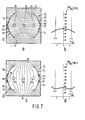
- Figure 7a shows in a manner analogous to that of Figures 5a and 6a a part of the picture field a number of field lines 70 of which are shown.
- two curved field shapers 71 and 72 are placed in said field and each consist of two curved plates 73, 74, and 75, 76 respectively, situated side by side in the elongation of each other on the same radius of curvature and two curved plates 79 and 80 overlapping the slots 77 and 78.
- the plates 79 and 80 may also be flat. From Figure 7b which is analogous to Figures 5b and 6b it follows that the picture field variation has not changed much as a result of the provision of the plates 79 and 80 as compared with the picture field variation shown in Figures 5b and 6b.
- Figure 7c shows a part of the line field a number of field lines 81 of which are shown. From Figure 7dwhich is analogous to Figure 6d it follows that, although the line field is attenuated by providing the slots 77 and 78, the variation in the x direction is also very flat. In other words, the line field is attenuated as compared with Figure 6d but is not strongly distorted. This also follows from the comparison of Figures 7c and 6c.
- Figure 8 is a sectional view analogous to Figure 3 through a centering cup 90.
- the curved field shapers 91 and 92 of this embodiment of the invention each consist of three plates 93, 95 which are situated side by side in the elongation of each other and on the same radius of curvature and having therebetween 1.3 mm wide slots 96 which on the outside are overlapped at 0.3 mm distance by plates 97 which each form a magnetic shunt on the line field.
- Figure 9 also shows in a manner analogous to Figure 3 a sectional view through a centering cup 100.
- the curved field shapers of this embodiment of the invention each consist of two bent plates 101, 102 and 103, 104, respectively, situated in the elongation of each other and two flat plates 105 and 106 which overlap the slots 107 and 108 respectively.
Landscapes
- Video Image Reproduction Devices For Color Tv Systems (AREA)
- Electrodes For Cathode-Ray Tubes (AREA)
Claims (3)
Applications Claiming Priority (2)
| Application Number | Priority Date | Filing Date | Title |
|---|---|---|---|
| NL8301712 | 1983-05-13 | ||
| NL8301712A NL8301712A (nl) | 1983-05-13 | 1983-05-13 | Kleurenbeeldbuis. |
Publications (2)
| Publication Number | Publication Date |
|---|---|
| EP0125729A1 EP0125729A1 (fr) | 1984-11-21 |
| EP0125729B1 true EP0125729B1 (fr) | 1988-04-27 |
Family
ID=19841853
Family Applications (1)
| Application Number | Title | Priority Date | Filing Date |
|---|---|---|---|
| EP84200667A Expired EP0125729B1 (fr) | 1983-05-13 | 1984-05-10 | Tube d'image en couleurs |
Country Status (9)
| Country | Link |
|---|---|
| US (1) | US4902928A (fr) |
| EP (1) | EP0125729B1 (fr) |
| JP (1) | JPS59215641A (fr) |
| KR (1) | KR840009368A (fr) |
| CA (1) | CA1208685A (fr) |
| DD (1) | DD217365A5 (fr) |
| DE (1) | DE3470817D1 (fr) |
| ES (1) | ES532370A0 (fr) |
| NL (1) | NL8301712A (fr) |
Families Citing this family (1)
| Publication number | Priority date | Publication date | Assignee | Title |
|---|---|---|---|---|
| JPS59214139A (ja) * | 1983-05-18 | 1984-12-04 | Matsushita Electronics Corp | カラ−受像管装置 |
Citations (1)
| Publication number | Priority date | Publication date | Assignee | Title |
|---|---|---|---|---|
| EP0109717A1 (fr) * | 1982-11-18 | 1984-05-30 | Koninklijke Philips Electronics N.V. | Tube image couleur |
Family Cites Families (7)
| Publication number | Priority date | Publication date | Assignee | Title |
|---|---|---|---|---|
| US3252032A (en) * | 1963-12-13 | 1966-05-17 | Sylvania Electric Prod | Electrode assembly locating means |
| JPS5520329B2 (fr) * | 1974-05-23 | 1980-06-02 | ||
| FR2413776A1 (fr) * | 1978-01-03 | 1979-07-27 | Thomson Csf | Objectif d'optique electronique |
| NL7802129A (nl) * | 1978-02-27 | 1979-08-29 | Philips Nv | Inrichting voor het weergeven van gekleurde beelden. |
| US4225804A (en) * | 1978-04-22 | 1980-09-30 | Gte Sylvania N.V. | Cathode ray tube coma correction device |
| JPS5738544A (en) * | 1980-08-19 | 1982-03-03 | Matsushita Electronics Corp | Electromagnetic deflection system picture tube system equipment |
| DE3126344A1 (de) * | 1981-07-03 | 1983-02-24 | Anton Dr. 7900 Ulm Casel | Ablenkeinheit fuer eine dreistrahlige farbfernseh-bildroehre |
-
1983
- 1983-05-13 NL NL8301712A patent/NL8301712A/nl not_active Application Discontinuation
-
1984
- 1984-05-10 EP EP84200667A patent/EP0125729B1/fr not_active Expired
- 1984-05-10 DE DE8484200667T patent/DE3470817D1/de not_active Expired
- 1984-05-10 CA CA000454061A patent/CA1208685A/fr not_active Expired
- 1984-05-10 ES ES532370A patent/ES532370A0/es active Granted
- 1984-05-10 DD DD84262914A patent/DD217365A5/de unknown
- 1984-05-11 JP JP59094398A patent/JPS59215641A/ja active Pending
- 1984-05-11 KR KR1019840002552A patent/KR840009368A/ko not_active Withdrawn
-
1986
- 1986-08-27 US US06/902,095 patent/US4902928A/en not_active Expired - Fee Related
Patent Citations (1)
| Publication number | Priority date | Publication date | Assignee | Title |
|---|---|---|---|---|
| EP0109717A1 (fr) * | 1982-11-18 | 1984-05-30 | Koninklijke Philips Electronics N.V. | Tube image couleur |
Also Published As
| Publication number | Publication date |
|---|---|
| DD217365A5 (de) | 1985-01-09 |
| DE3470817D1 (en) | 1988-06-01 |
| JPS59215641A (ja) | 1984-12-05 |
| ES8502809A1 (es) | 1985-01-16 |
| KR840009368A (ko) | 1984-12-26 |
| ES532370A0 (es) | 1985-01-16 |
| CA1208685A (fr) | 1986-07-29 |
| NL8301712A (nl) | 1984-12-03 |
| EP0125729A1 (fr) | 1984-11-21 |
| US4902928A (en) | 1990-02-20 |
Similar Documents
| Publication | Publication Date | Title |
|---|---|---|
| US4629933A (en) | Cathode-ray tube having an electron gun with an astigmatic focusing grid | |
| CA1211780A (fr) | Tube-image multichrome | |
| JPS5811070B2 (ja) | カラ−ヒヨウジソウチ | |
| EP0109717B1 (fr) | Tube image couleur | |
| US4346327A (en) | Display tube for displaying color pictures | |
| US4556819A (en) | Color picture tube having inline electron gun with coma correction members | |
| US4890032A (en) | Color display tube having electrode converging means | |
| US4625145A (en) | Color display tube with magnetic field shaping means | |
| EP0125729B1 (fr) | Tube d'image en couleurs | |
| EP0490004A1 (fr) | Bobine de déflexion avec promoteur pour les harmoniques du champ magnétique | |
| EP0170319B1 (fr) | Tube image couleur | |
| US4370593A (en) | In-line electron gun and method for modifying the same | |
| US4634923A (en) | Color picture tube having improved electron gun | |
| EP0243541B1 (fr) | Tube d'affichage pour télévision en couleurs avec correction de coma | |
| JP2636217B2 (ja) | カラーテレビジョン表示管 | |
| US5014029A (en) | Deflection yoke for cathode ray tube | |
| EP0755569B1 (fr) | Tube a rayons cathodiques de couleur comprenant un canon electronique en ligne | |
| EP0257639A2 (fr) | Tube d'image couleur comportant un canon à électrons en ligne avec des moyens de correction de coma | |
| JPS6353664B2 (fr) | ||
| US4691139A (en) | Display tube having ferromagnetic field shapers to prevent beam defocussing | |
| JP3396503B2 (ja) | カラー受像管装置 | |
| CN85102068A (zh) | 彩色显像管 | |
| JPH07147147A (ja) | カラー陰極線管のビームの軸ずれ補正装置 | |
| JPS63226858A (ja) | カラ−受像管装置 |
Legal Events
| Date | Code | Title | Description |
|---|---|---|---|
| PUAI | Public reference made under article 153(3) epc to a published international application that has entered the european phase |
Free format text: ORIGINAL CODE: 0009012 |
|
| AK | Designated contracting states |
Designated state(s): DE FR GB IT NL |
|
| 17P | Request for examination filed |
Effective date: 19841224 |
|
| R17P | Request for examination filed (corrected) |
Effective date: 19841224 |
|
| 17Q | First examination report despatched |
Effective date: 19860421 |
|
| GRAA | (expected) grant |
Free format text: ORIGINAL CODE: 0009210 |
|
| AK | Designated contracting states |
Kind code of ref document: B1 Designated state(s): DE FR GB IT NL |
|
| PG25 | Lapsed in a contracting state [announced via postgrant information from national office to epo] |
Ref country code: NL Effective date: 19880427 |
|
| REF | Corresponds to: |
Ref document number: 3470817 Country of ref document: DE Date of ref document: 19880601 |
|
| ITF | It: translation for a ep patent filed | ||
| ET | Fr: translation filed | ||
| NLV1 | Nl: lapsed or annulled due to failure to fulfill the requirements of art. 29p and 29m of the patents act | ||
| PLBE | No opposition filed within time limit |
Free format text: ORIGINAL CODE: 0009261 |
|
| STAA | Information on the status of an ep patent application or granted ep patent |
Free format text: STATUS: NO OPPOSITION FILED WITHIN TIME LIMIT |
|
| 26N | No opposition filed | ||
| ITTA | It: last paid annual fee | ||
| ITPR | It: changes in ownership of a european patent |
Owner name: CAMBIO RAGIONE SOCIALE;PHILIPS ELECTRONICS N.V. |
|
| REG | Reference to a national code |
Ref country code: FR Ref legal event code: CD |
|
| PGFP | Annual fee paid to national office [announced via postgrant information from national office to epo] |
Ref country code: DE Payment date: 19950724 Year of fee payment: 12 |
|
| PGFP | Annual fee paid to national office [announced via postgrant information from national office to epo] |
Ref country code: GB Payment date: 19960430 Year of fee payment: 13 |
|
| PGFP | Annual fee paid to national office [announced via postgrant information from national office to epo] |
Ref country code: FR Payment date: 19960530 Year of fee payment: 13 |
|
| PG25 | Lapsed in a contracting state [announced via postgrant information from national office to epo] |
Ref country code: DE Effective date: 19970201 |
|
| PG25 | Lapsed in a contracting state [announced via postgrant information from national office to epo] |
Ref country code: GB Effective date: 19970510 |
|
| GBPC | Gb: european patent ceased through non-payment of renewal fee |
Effective date: 19970510 |
|
| PG25 | Lapsed in a contracting state [announced via postgrant information from national office to epo] |
Ref country code: FR Free format text: LAPSE BECAUSE OF NON-PAYMENT OF DUE FEES Effective date: 19980130 |
|
| REG | Reference to a national code |
Ref country code: FR Ref legal event code: ST |