EP0125741B1 - Détecteur pour des objets enterrés - Google Patents
Détecteur pour des objets enterrés Download PDFInfo
- Publication number
- EP0125741B1 EP0125741B1 EP84300333A EP84300333A EP0125741B1 EP 0125741 B1 EP0125741 B1 EP 0125741B1 EP 84300333 A EP84300333 A EP 84300333A EP 84300333 A EP84300333 A EP 84300333A EP 0125741 B1 EP0125741 B1 EP 0125741B1
- Authority
- EP
- European Patent Office
- Prior art keywords
- detector
- coils
- output
- ground
- signal
- Prior art date
- Legal status (The legal status is an assumption and is not a legal conclusion. Google has not performed a legal analysis and makes no representation as to the accuracy of the status listed.)
- Expired - Lifetime
Links
- 230000005291 magnetic effect Effects 0.000 claims description 88
- 238000001514 detection method Methods 0.000 claims description 19
- 230000008859 change Effects 0.000 claims description 15
- 238000000034 method Methods 0.000 claims description 15
- 239000000463 material Substances 0.000 claims description 11
- 230000035945 sensitivity Effects 0.000 claims description 10
- 238000010408 sweeping Methods 0.000 claims description 7
- 238000012360 testing method Methods 0.000 claims description 7
- 239000003550 marker Substances 0.000 claims description 5
- 230000008447 perception Effects 0.000 claims description 4
- 230000004907 flux Effects 0.000 claims description 3
- 230000003321 amplification Effects 0.000 claims description 2
- 238000003199 nucleic acid amplification method Methods 0.000 claims description 2
- 230000005236 sound signal Effects 0.000 claims 1
- 239000002689 soil Substances 0.000 description 19
- 239000004033 plastic Substances 0.000 description 13
- 229920003023 plastic Polymers 0.000 description 13
- 239000002184 metal Substances 0.000 description 12
- 229910052751 metal Inorganic materials 0.000 description 12
- 230000006698 induction Effects 0.000 description 6
- 239000011435 rock Substances 0.000 description 5
- 230000006870 function Effects 0.000 description 4
- 239000002245 particle Substances 0.000 description 4
- 230000008901 benefit Effects 0.000 description 3
- 238000001914 filtration Methods 0.000 description 3
- 229910052500 inorganic mineral Inorganic materials 0.000 description 3
- 239000000696 magnetic material Substances 0.000 description 3
- 239000011707 mineral Substances 0.000 description 3
- XLYOFNOQVPJJNP-UHFFFAOYSA-N water Substances O XLYOFNOQVPJJNP-UHFFFAOYSA-N 0.000 description 3
- RYGMFSIKBFXOCR-UHFFFAOYSA-N Copper Chemical compound [Cu] RYGMFSIKBFXOCR-UHFFFAOYSA-N 0.000 description 2
- XEEYBQQBJWHFJM-UHFFFAOYSA-N Iron Chemical compound [Fe] XEEYBQQBJWHFJM-UHFFFAOYSA-N 0.000 description 2
- 238000004458 analytical method Methods 0.000 description 2
- 230000015572 biosynthetic process Effects 0.000 description 2
- 238000009933 burial Methods 0.000 description 2
- 238000010586 diagram Methods 0.000 description 2
- 230000000694 effects Effects 0.000 description 2
- 239000001307 helium Substances 0.000 description 2
- 229910052734 helium Inorganic materials 0.000 description 2
- SWQJXJOGLNCZEY-UHFFFAOYSA-N helium atom Chemical compound [He] SWQJXJOGLNCZEY-UHFFFAOYSA-N 0.000 description 2
- 229910052595 hematite Inorganic materials 0.000 description 2
- 239000011019 hematite Substances 0.000 description 2
- LIKBJVNGSGBSGK-UHFFFAOYSA-N iron(3+);oxygen(2-) Chemical compound [O-2].[O-2].[O-2].[Fe+3].[Fe+3] LIKBJVNGSGBSGK-UHFFFAOYSA-N 0.000 description 2
- SZVJSHCCFOBDDC-UHFFFAOYSA-N iron(II,III) oxide Inorganic materials O=[Fe]O[Fe]O[Fe]=O SZVJSHCCFOBDDC-UHFFFAOYSA-N 0.000 description 2
- 238000005259 measurement Methods 0.000 description 2
- 150000002739 metals Chemical class 0.000 description 2
- 230000009467 reduction Effects 0.000 description 2
- 238000004804 winding Methods 0.000 description 2
- 241001422033 Thestylus Species 0.000 description 1
- 239000000956 alloy Substances 0.000 description 1
- 229910045601 alloy Inorganic materials 0.000 description 1
- 238000013459 approach Methods 0.000 description 1
- 239000000872 buffer Substances 0.000 description 1
- 229910052793 cadmium Inorganic materials 0.000 description 1
- BDOSMKKIYDKNTQ-UHFFFAOYSA-N cadmium atom Chemical compound [Cd] BDOSMKKIYDKNTQ-UHFFFAOYSA-N 0.000 description 1
- 238000010276 construction Methods 0.000 description 1
- 239000013078 crystal Substances 0.000 description 1
- 238000000354 decomposition reaction Methods 0.000 description 1
- 230000001934 delay Effects 0.000 description 1
- 230000008030 elimination Effects 0.000 description 1
- 238000003379 elimination reaction Methods 0.000 description 1
- 230000002349 favourable effect Effects 0.000 description 1
- 230000005294 ferromagnetic effect Effects 0.000 description 1
- 239000007789 gas Substances 0.000 description 1
- 230000001939 inductive effect Effects 0.000 description 1
- 238000013101 initial test Methods 0.000 description 1
- 238000011835 investigation Methods 0.000 description 1
- 229910052742 iron Inorganic materials 0.000 description 1
- JEIPFZHSYJVQDO-UHFFFAOYSA-N iron(III) oxide Inorganic materials O=[Fe]O[Fe]=O JEIPFZHSYJVQDO-UHFFFAOYSA-N 0.000 description 1
- 239000007788 liquid Substances 0.000 description 1
- 229910001092 metal group alloy Inorganic materials 0.000 description 1
- 239000007769 metal material Substances 0.000 description 1
- 238000004452 microanalysis Methods 0.000 description 1
- 239000000203 mixture Substances 0.000 description 1
- 239000003973 paint Substances 0.000 description 1
- 230000008569 process Effects 0.000 description 1
- 238000012545 processing Methods 0.000 description 1
- 230000001681 protective effect Effects 0.000 description 1
- 238000011160 research Methods 0.000 description 1
- 238000005507 spraying Methods 0.000 description 1
- 239000002887 superconductor Substances 0.000 description 1
- 230000000007 visual effect Effects 0.000 description 1
- 239000002023 wood Substances 0.000 description 1
Images
Classifications
-
- G—PHYSICS
- G01—MEASURING; TESTING
- G01V—GEOPHYSICS; GRAVITATIONAL MEASUREMENTS; DETECTING MASSES OR OBJECTS; TAGS
- G01V3/00—Electric or magnetic prospecting or detecting; Measuring magnetic field characteristics of the earth, e.g. declination, deviation
- G01V3/08—Electric or magnetic prospecting or detecting; Measuring magnetic field characteristics of the earth, e.g. declination, deviation operating with magnetic or electric fields produced or modified by objects or geological structures or by detecting devices
- G01V3/087—Electric or magnetic prospecting or detecting; Measuring magnetic field characteristics of the earth, e.g. declination, deviation operating with magnetic or electric fields produced or modified by objects or geological structures or by detecting devices the earth magnetic field being modified by the objects or geological structures
-
- G—PHYSICS
- G01—MEASURING; TESTING
- G01V—GEOPHYSICS; GRAVITATIONAL MEASUREMENTS; DETECTING MASSES OR OBJECTS; TAGS
- G01V3/00—Electric or magnetic prospecting or detecting; Measuring magnetic field characteristics of the earth, e.g. declination, deviation
- G01V3/15—Electric or magnetic prospecting or detecting; Measuring magnetic field characteristics of the earth, e.g. declination, deviation specially adapted for use during transport, e.g. by a person, vehicle or boat
Definitions
- This invention relates to a method and apparatus for detecting a localised disturbance in the ground.
- the invention finds particular application in the detection of plastic encased mines but can also be used forthe detection of metal encased mines, the detection of water or gas pipes, electric cables or other buried objects.
- Metal detectors are well known but these can of course only be used for detecting the presence of magnetically susceptible metallic objects below the surface of the ground.
- the known devices cannot be used for detecting non-metallic objects such as plastic pipes or plastic encased mines buried below the surface of the ground.
- An example of a known metal detector is given in document EP-A-0096380 which was published on 21st December 1983 (priority: 05.06.82).
- a method of detecting a localised disturbance in the ground comprising the step of sweeping an area of the ground with a detector which is responsive to the horizontal gradient of the earths magnetic field and which comprises a plurality of mutually spaced apart detector units, and detecting a change in the output from the detector units due to a change in said gradient caused by the localised disturbance and producing a signal capable of direct human perception when such change is detected, whereby the change in output from thedetector units is achieved without the detector supplying power to the detector units.
- a detector for use in the method of the first aspect of the invention which detector detects the edges of a localised disturbance in the ground and is capable of detecting non- magnetic buried objects
- the detector comprising two detector units which are co-planar and horizontally spaced apart and adapted to be used to sweep an area of the ground, the detector units together being responsive to the horizontal gradient of the earths magnetic field and adapted to respond to a change in said gradient caused by the edges of the localised disturbance so as to produce an output signal, and circuit means responsive to the output signal to produce a signal capable of direct human perception.
- the soil contains various minerals amongst them are essentially common hematite, magnetite, maghemite (magnetic hematite), ibnenite. These and other magnetically susceptible materials have their origin in the decomposition of rocks and are spread by water and wind on the surface of the ground and penetrate into the soil by rain, water and cultivation of the ground. The later factor is important in inhabited areas. A further supply of these minerals is provided by convection currents in the lower atmosphere. Powerful convection currents carry particles from the surface of rocks and the ground into the atmosphere. These particles are spread and deposited on the soil surface by inversion currents. Amongst such particles iron and magnetite are most common. This fact is clearly demonstrated by the micro analysis of airborne particles and such analysis has been carried out by the inventor.
- An average value of the intensity of the earths mangetic field is 0-5 Oersted which can be expressed as 0.5 x 10 5 gamma.
- the magnetic intensity at ground level would be reduced by the digging of a hole, say 10 centimetres in diameter, by a value in the range of 1 to 5 gamma. If the magnetic anomaly caused by the hole is to be detected by variation of the ground level magnetic intensity then it can be seen that the sensitivity of detection would have to be in the range of one part in ten thousand to one part in fifty thousand. It would be difficult to construct a detector with a reliable sensitivity of this order. However, it is a known scientific fact that the gradient of a field of force can be measured with much higher sensitivity than the force itself. The present invention is therefore designed to take advantage of this fact.
- the invention utilises the magnetic gradient, that is the differential of magnetic field strength with respect to distance.
- the horizontal gradient of the vertical component of the magnetic field identifies the edge of the hole in which the object is buried whereas the peak of the change in intensity tends to identify only the centre of the disturbance. This means that the shape and size of the buried object can be determined and this will give some indication as to whether or not the buried object is likely to be of interest.
- the second aspect of the magnetic characteristic is that a buried magnetically susceptible metallic object will increase the strength of the local magnetic field whereas a buried non-magnetically susceptible object will decrease the strength of the local field.
- the sign of the horizontal magnetic gradient encountered when traversing an area of ground containing a buried object will therefore give an indication as to whether the buried object is magnetically susceptible or not.
- traversing across the area containing the object one will first encounter a positive horizontal magnetic gradient and will subsequent encounter a negative horizontal magnetic gradient when passing over the buried object.
- the signs of the gradients is reversed when one traverses across a buried non-magnetically susceptible object.
- the present invention provides a method and apparatus responsive to changes in the horizontal gradient of the earths magnetic field resulting from a buried object and it is believed that the above described theory illustrates the particular function and advantages of this method and apparatus.
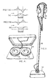
- Figures 1 and 2 illustrate the physical characteristics enabling operating of the present invention.
- the line drawing indicates a hole which has been dug in the ground with an object placed at the bottom of the hole and the hole subsequently refilled with the displaced material.
- the buried object is formed of a magnetically susceptible material and in figure 2 the buried object is formed of a non-magnetically susceptible material.
- Line drawing (a) of each figure illustrates the change in the intensity of the local magnetic field at ground level resulting from formation of the hole and the burying of the respective object.
- Line drawing (b) of each figure represents the change in horizontal gradient of the vertical component of the magnetic field resulting from formation of the hole and burying of the respective object, as encountered when traversing the area of the buried object in the direction indicated by the arrows. It is evident from figures 1 and 2 line drawings (b), that the horizontal gradient of the vertical component of the magnetic field not only indicates relatively precisely the boundaries of the hole and buried object but also provides an indication of the magnetic susceptibility of the material from which the buried object is formed or is partially formed.
- the detector of the present invention comprises two coils spaced apart in a common plane and electrically connected in series opposition to a detector circuit. Movement of the detector in a horizontal plane just above the surface of the ground will cause the coils to cut lines of the earths magnetic field which at most places on the surface of the earth are inclined to the horizontal.
- the apparatus is arranged such that where the ground is undisturbed and the magnetic field is uniform, the detector circuit produces no output. At the point in the scanning movement when one coil is moving over undisturbed ground and the other coil enters an area of magnetic disturbance, the output from the coils is unbalanced and this can produce a signal in the output circuit such that the boundary of the disturbance is indicated.
- an outline plan of a hole in the ground can be made whether or not the hole contains an article without measurable magnetic susceptibility or a magnetically susceptible article.
- the detector instrument is free from any material or component that possesses any but the very minimum magnetic susceptibility.
- fluxgates could be used in certain conditions, the preference is for induction coils wound on entirely nonmagnetic cores, such as plastics or suitable wood, etc.
- the detector consists of two co-planar and identical coils wound on identical cores of non- magnetic material.
- the coils are made up of 5000-10,000 turns of thin insulated copper wire.
- the diameter of the coils varies according to the size of the objects buried in the soil, the detection of which is the objective of any given case. A further factor is the efficiency required in covering large areas.
- the two coils are wound and tested so as to give identical output when moving in homogeneous magnetic fields.
- the coils are connected in opposition, and fixed to the same portable frame or platform, any irregularity in the coil windings which may cause differences in their induced e.m.f. is balanced out electrically.
- the geometry of the coil shape and its size is chosen according to the size of the target of detection. Similarly the distance between the centres of the coils chosen according to the size and order of the depth of the burial of the target objects in the soil. For these reasons coils of different sizes and shapes are interchangeable by simply plugging them into the amplifier and filter circuit.
- the angle of the container box of the coils at the end of the handle can be changed to approach the position at right angles to the inclination of the earth magnetic field.
- the container of the coils and thereby the two coils can be rotated at the end of the handle and fitted in a desired orientation relative to the magnetic declination of the earth magnetic field. This is necessary when the horizontal gradient of the magnetic field is to be detected in different directions from the same position of the operator, in order to locate the edges of the hole in the soil, or of the object buried in the soil and thereby give the size and shape of the target.
- the detector comprises two detector units in the form of coils 10, 12 the diameters of which are preferably small in relation to the size of the object to be detected.
- the coils 10, 12 are mounted in a head 14 such that the distance between the coils is variable. This distance may be varied for use in successive tests over the same area of ground or for use when searching for objects of different size.
- the head 14 is mounted on a handle 16 at a variable angle to suit the convenience of the user so that in use the coils 10, 12 will be in a horizontal plane a little above the surface of the earth.
- the coils 10, 12 may be spaced apart transversely to the vertical plane containing the handle 16 in use, or may have their centres spaced apart in that plane so that with the user carrying the handle 16 in front of him a scan will be effected merely by the user walking forwards.
- the angle of the line joining the centres of the coils 10, 12 to the vertical plane containing the handle can be variable to suit the particular application.
- the upper end of the handle 16 carries a module 18 containing the detector circuit and a power supply. By mounting the electric circuit and power supply the upper end of the handle disturbance of the magnetic characteristics to be detected is minimized.
- the head 14 embodies a pair of horizontally disposed, horizontally separated inductive coils 10, 12 each, in the example being described, having five thousand turns, an internal diameter of 60 mm and an external diameter of 80mm.
- the centres of the coils 10, 12 are spaced apart by 157 mm but an adjustable mounting (not shown) is included to enable the space in between the coil centres to be readily adjusted.
- the coils 10, 12 are mounted in a protective casing.
- the coils 10, 12 described have an external diameter of 80 mm there will be applications where coils of other diameters might be preferred.
- the coils might have an external diameter in the range of 20 mm to 300 mm.
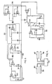
- Figure 5 is a circuit diagram in block form of the circuit contained in the module 18 at the upper end of the handle 16 of the detector.
- the coils 10, 12 are connected to respective operational amplifiers LC.1 and LC.2.
- the operational amplifiers act as high impedance buffers for the respective coils 10, 12.
- Operational amplifier I.C.1 has a feed back circuit including a variable potentiometer 20 which can be used to adjust the relative outputs from the coils 10, 12. It should be appreciated that it is preferable for the coils to be as nearly identical as is practical.
- the operational amplifiers LC.1 and I.C.2 may each be implemented by a respective half of a standard O.P. 227 integrated circuit component. The output from operational amplifier LC.1 is fed into operational amplifier LC.2.
- the output of LC.2 is applied to a filtering section of the circuit consisting of a first filter 22 designed to reject frequencies of above approximately 40 hertz and a second filter 24 designed to reject frequencies of less than 1 hertz.
- the first 22 filter is implemented as a conventional Sallen-Key low pass filter comprising operational amplifier LC.3.
- the second filter 24 is a simple R.C circuit.
- Operational amplifier I.C.3 may be implemented as one half of a conventional O.P. 227 integrated circuit component.
- Output from the filtering section is applied to a high gain operational amplifier LC.4. This operational amplifier may be formed of the other half of the O.P. 227 component used in the Sallen-key filter.
- Operational amplifier I.C.4 has a variable potentiometer 26 in a feed back circuit and this potentiometer 26 is used to adjust the sensitivity of the detector circuit.
- Output from operational amplifier I.C. 4 is applied to a full wave rectifying circuit 28 implemented in two parts each having a respective integrated circuit component I.C.5, LC.6forwhich a conventional C.A. 31305 unit may be used in each case.
- Output from the full wave rectifying circuit 28 is applied to a comparator which employs integrated circuit I.C.7. I.C.7 may also be in the form of the conventional C.A. 31305 component.
- output from the full wave rectifying circuit 28 is compared with a signal from a tone generating circuit 30 which is of conventional construction.
- Output from the tone generating circuit 30 is applied to the comparator via an adjustable potentiometer 32 and adjustment of this potentiometer 32 enables a threshold level to be set for output from the detector circuit.
- Output from the comparator is applied to a pair of headphones 34 which are to be worn by the operator of the detector. It will be appreciated that the arrangement of the tone generating circuit 30 and the comparator is such that an audible signal is produced in the headphones 34 when the output from the full wave rectifying circuit 28 exceeds the signal level set by the threshold potentiometer 32.
- the operator swings the detector head 14 containing the induction coils 10, 12 at the end of a 150 cm long handle 16.
- the operator hears a number of sharp signals. Similar signals occur over the edges of buried objects whenever the magnetic susceptibility is lower or higher than that of the soil. As it was stated earlier the number of the signals vary according to the size of the coils and the distance between the coils, and the size of the hole or of the buried object.
- the coils are selected and located at such distance from each other that whenever an edge of the coil passes over the edge of a hole or of a buried object, a sharp signal is heard in the headphones.
- the first sharp pulse is produced by the peak in the horizontal gradient of the vertical component of the magnetic field and one sharp signal is heard in the headphones.
- a third pulse causes a third signal to be heard.
- a fourth pulse causes a sharp signal in the headphones.
- the second coil will cause, in a similar manner, four other signals as it passes over the target.
- the gist of the results is that a series of pulses and consequent signals are produced by the instrument when swept over ground disturbed by holes and/or by buried objects.
- the operator repeats his sweep with the detector. He now marks the point of the first signal on the ground. This can be done by spraying a paint or using another marker on the ground.
- the operator now repeats the sweep in the opposite direction, and marks the ground where the first signal occurs in this direction of the sweep. This point coincides with that of the last signal of the first sweep. He then continues the sweep and marks the ground where the last signal occurs. This point coincides with the first signal of the first sweep.
- the distance between the two signals marks the distance between two edges of the target and gives the width of the buried hole or object in the ground.
- the width of the target can be determined in different directions, hence the shape of the hole or object can be determined.
- the metal detectors used for the detection of buried metallic mines cannot differentiate between mines and so-called "tramp metals", i.e. metal debris which is especially abundant in war conditions. Consequently a large number of false alarms are produced, each of which has to be investigated and identified, this causes delays, thereby holding up important operations.
- peaks in the values of the horizontal gradient of the earth magnetic field delineate holes in the soil, whether or not such holes are re-filled by the disturbed soil.
- the magnetic susceptibility is reduced by two factors. Firstly, the broken up soil, with which a hole would be re-filled has lost its magnetic susceptibility even long after the burial of the mine. Secondly, the plastic mine itself occupying a part of the hole has a minimal value of magnetic susceptibility. The result is a reduction of the vertical component of the earths magnetic field.
- the size of the mine is known, and the size of the hole can be determined by the present invention as has already been described.
- a buried object of higher magnetic intensity than that of the soil will show the reverse of the above curve as the detector passes from the soil of normal magnetic susceptibility to an area of higher susceptibility and subsequently back to lower, normal, magnetic susceptibility.
- the Detector not only gives the size of buried objects but can also detect whether the changes in horizontal gradient of the earth magnetic field are caused by objects the size and magnetic susceptibility of which coincide with known characteristics.
- the known characteristics can be determined by burying samples of plastic mines in the area where the detection of such mines is required.
- the two induction coils of superconducting metals or alloys.
- Such coils would have zero electrical resistance and are especially efficient in conducting direct current without measurable losses, such as occur when such coils are charged with alternating current.
- Such coils would have a few turns of cadmium or suitable metal alloys, refrigerated by liquid helium and enclosed in small portable cryostats. The latter could be recharged from storage cryostats containing reserve helium.
- Submarine detection is one of such special problems, the detection of land and sea mines is another possible application. Another application would be the detection of hidden tanks and missile bases with the detectors being carried by aircraft.
- the circuit illustrated in figure 5 and described above generates an audible output it is possible to implement the final output in a variety of alternative forms.
- the output may be indicated by a meter and it may alternatively be possible to mount a recording chart on the handle with an indicating pen which moves over the chart as the head scans. This would give a visual indication of the scans in plan view which can be related to the positions of the blips in the output signal.
- the detector can be implemented in a simple and mechanically robust manner.
- a detector comprising a pair of preferably identical coils, which may be circular or may be of some other shape
- a pair of flux gates that is to say a pair of devices each including a ferro-magnetic core having a characteristic axis and carrying an output winding.
- the cores would be positioned side by side horizontally in a direction transverse to the characteristic core directions with the coils connected in series opposition.
- the use of flux gates will probably incur disadvantages due to their cost and the fact that the magnetic characteristic of their cores may disturb the magnetic characteristics which it is desired to detect.
- the shape and size of a buried object may be determined by measuring the distance between the opposing pulses corresponding to the gradients indicated by line drawings (b) in figures 1 and 2.
- One method of achieving this result is to support the detector handle on a tripod.
- the handle may be graduated in centimeters and the angle between the two pulses, one at each edge of the buried object, can be read on a scale of degrees attached to the fixed tripod. Knowing the distance from the fixed pivot of the tripod to the coils, the width of the buried object can be determined by simple trigonometry. A simple computer, or even a table can be used.
- the recording of the width of the buried object can be acheived by fixing a pad to a fixed support carrying the fulcrum.
- a sheet of recording material On this pad is fixed a sheet of recording material.
- a stylus or other recording device Fixed to the handle of the detector is a stylus or other recording device which marks the material on the fixed pad.
- the stylus moves with the movement of the handle, that is with movement of the detector coils.
- the pulses of the detector at the edges of the buried object can be transmitted by the detector circuit so as to mark the material of the sheet on the pad, thus indicating the width of the buried object.
- the head may be mounted on the handle through a spring arrangement causing the head to be automatically oscillated transversely and repeatedly at an approximately predetermined rate. If the rate of the scanning is known, information concerning the discontinuity can be derived from the amplitude of the blips.
- the spring By including a flat spring joint in the handle of the detector, the spring preferable being of a non-metallic material, it is possible to oscillate the detector coils rapidly so as to increase the sensitivity of the detector even if the operator swings the coils relatively slowly.
- the coils could be fixed to a suitable non-metallic frame and embodied in a streamline housing and may thus be used for the detection of submarines, and ship wrecks including old wooden ships.
- towing coils of suitable size in a pod from a helicopter or aeroplane it is possible to detect the boundaries of a mine field, the presence of hidden armed units, munition stores, underground tunnels systems, underground pipelines and the like.
- An object of the present embodiment is to provide means reducing the likelihood of obtaining a false indication that the detector has encountered a mine or other body requiring detection.
- a preliminary test is performed on a sample object which is later to be detected, so that the characteristic output signal derived from a scan with the detector over the sample object can be recorded, coded and stored in the memory of a computer for subsequent use as a reference when searching for objects in a certain area.
- the sample object for example a plastic mine, is likely to have metallic or metal components which will give characteristic output signals, in addition to the signals at the edges of the cavity where the object is buried, as described.
- the signals picked up from components of the mine all form part of the characteristic of that mine produced by scanning it with the detector.
- the detector for use in the field can then embody a computer which will have stored in its memory, a coded version of the characteristic signal of the mine which is being searched for.
- the computer can also be programmed so that as the detector is used in the field, any signal received representing a magnetic discontinuity can be compared with the pre-recorded charc- teristic signal in the memory and if there is little similarity, then no output signal will be given.
- the detector coils are square in plan view, the squares having sides 10cms long.
- the distance between the centres of the two coils is 20cms, so that the total width of the two detector coils and the spacing between them is 30cms.
- a typical scanning sweep might be 200 cms in amplitude and might take 2 seconds i.e. 1cm per 0.01 second.
- the length of scan between the first encounter of the mine by the leading side of the first coil and the last encounter with the other edge of the mine by the trailing edge of the second coil will be 20cms, and at the rate described above, that would be scanned in 0.3 seconds.
- the spacing between, say, a signal where the trailing edge of one coil encountered the mine first, and the leading edge of the other coil encountered the mine first, would be 10cms and that would be scanned in 0.1 seconds, a time which is too short to be easily recognised by the ear.
- the detector is arranged to have a clock driven from a crystal oscillator, or possibly even controlled by the scanning movement of the detector, so as to generate time marking pulses at regular intervals of say, .001 seconds, so that in the full 2 second sweep there would be 2,000 time marker pulses.
- the detected signals can be superimposed on series of time marker pulses, so that the spacing between different components of a detected signal can be easily determined and fed to the computer.
- a characteristic signal for that mine can be generated, and recorded, and that will show where the various peaks occur in relation to the time steps in the complete scan.
- the amplitudes of the characteristic signal at each time marker could be coded digitally and recorded in a computer memory.
- the sample mine includes a magnetic or even a metal component, or possible more than one, each of those will also produce a series of four peaks in the output signal, and they will form further components of the characteristic signal to be recorded.
- the computer in a detector to be used when searching for similar mines in a particular area will have stored in its memory, the characteristic signal of the mine that is being searched for.
- the output signal can be continously compared with the characteristic signal stored in the memory, so that if a similar signal appears in the output, it can be assumed that a mine has been found, and a warning signal can be given.
- the computer need be only a small component of the detector, and in addition to the memory for storing the, characteristic signal the computer can contain a program which controls the comparison of the continuously received output signal with the memory signal.
- the computer may also allow for measurement of the speed of scan in the field, and may also allow for compensation for any variation between that speed of scan and the speed at which the characteristic signal was obtained in the initial test.
- the above described arrangements function by detecting the horizontal gradient of the earths magnetic field.
- the present embodiment seeks to improve the sensitivity of a detector by detecting gradients in two planes namely, horizontal and vertical planes.
- a detector comprises a first pair of induction coils spaced apart in a first horizontal plane, and a second pair of induction coils spaced apart in a second horizontal plane, and electrical connection means for connecting the coils to an output circuit.
- the coils are arranged such that respective ones of the first and second pair are aligned vertically.
- the electrical connection means is arranged selectively to connect the first pair of coils in opposition to an output circuit.
- the electrical connection means is also arranged selectively to connect the first coils of the two pairs in opposition to an output circuit and the second coils of the pairs in opposition to an output circuit.
- the electrical connection means connects the first coil of the first pair and the second coil of the second pair in opposition to an output circuit and also connects the second coil of the first pair and the first coil of the second pair in opposition to an output circuit.
- each coil lies at a respective apex of a notional parallelogram.
- the outputs of the coils in each of the horizontal planes can be balanced so that no signals are generated when the detector is moved in a homogeneous magnetic field.
- the outputs of the first coils of each of the pairs, and the second coils of each of the pairs may also be balanced, so as to generate no signal if the vertical gradient of the magnetic field remains constant.
- the electrical connection means may include appropriate switching means to make it possible readily to change the connections between the coils. It will be appreciated that by connecting respective coils in opposition, the pairs of coils in either of the horizontal planes is directly equivalent to the above described two coil embodiment of the invention.
- first coils of each pair or the second coils of each pair may also be, selectively, connected in opposition to an output circuit.
- the embodiment also provides a detector comprising two coils, each coil lying in a different horizontal plane with the coils being electrically connected in opposition to an output circuit.
- the interconnected coils may be arranged one vertically above the other on a common axis or on different vertical axes.
- This arrangement may be used for detecting vertical magnetic gradients.
- the gradient of a magnetic field is the second derivative, with respect to position, of the magnetic potential.
- Such derivatives satisfy the Laplace's equation.
- the vertical gradient of the earths magnetic field can be determined by the sum of the horizontal gradients in two mutually orthogonal directions.
- An embodiment of the invention for detecting vertical magnetic gradient may therefore be formed of four co-planar coils.
- the coils are connected in two pairs, each pair determining the horizontal gradient in a respective orthogonal direction.
- the two pairs are connected such that their outputs are summed. Sweeping the detector horizontally will thus generate a signal indicative of the vertical magnetic gradient.
- this embodiment can, of course, be used to give simply the horizontal gradients in the two horizontal directions.
- characteristic output signals corresponding to both horizontal and vertical magnetic field gradients can be derived from a scan with a detector over a sample object.
- the characteristic output signals can then be recorded, coded and stored in the memory of a computer for subsequent use as a reference when searching for objects in a certain area.
- Such characteristic output signals can be obtained by way of a preliminary test performed on a sample object in an environment similar to that in which it is likely to be detected.
- the distance between the two horizontal planes can be varied.
- Figure 6 shows a first pair of coils 36 and 38 lying in a first common plane, and a second pair of coils 40 and 42 lying in a second common plane parallel to the first common plane.
- the first and second common planes are horizontal.
- the coil 40 is vertically aligned above the coil 36
- the coil 42 is vertically aligned above the coil 38.
- Each of the coils 36, 38, 40 and 42 is connected to electrical connection means 44, which is capable of connecting various combinations of the coils 36,38,40 and 42 in opposition to an output circuit.
- the detector can only detect changes in the horizontal gradient of a magnetic field.
- the detector can only detect changes in the vertical gradient of a magnetic field.
- both a horizontal pair of coils such as 36 and 38
- a vertically aligned pair of coils such as 40 and 42
- the four coils 36, 38, 40 and 42 are all mounted on a rigid frame (not shown) which is adjustable so that the distance between the two common planes can be changed.
Landscapes
- Life Sciences & Earth Sciences (AREA)
- Engineering & Computer Science (AREA)
- Remote Sensing (AREA)
- Environmental & Geological Engineering (AREA)
- Geology (AREA)
- Physics & Mathematics (AREA)
- General Life Sciences & Earth Sciences (AREA)
- General Physics & Mathematics (AREA)
- Geophysics (AREA)
- Geochemistry & Mineralogy (AREA)
- Electromagnetism (AREA)
- Geophysics And Detection Of Objects (AREA)
Claims (17)
Applications Claiming Priority (6)
| Application Number | Priority Date | Filing Date | Title |
|---|---|---|---|
| GB8301529 | 1983-01-20 | ||
| GB8301529 | 1983-01-20 | ||
| GB8311464 | 1983-04-27 | ||
| GB8311464 | 1983-04-27 | ||
| GB8314804 | 1983-05-31 | ||
| GB8314804 | 1983-05-31 |
Publications (3)
| Publication Number | Publication Date |
|---|---|
| EP0125741A2 EP0125741A2 (fr) | 1984-11-21 |
| EP0125741A3 EP0125741A3 (en) | 1986-06-25 |
| EP0125741B1 true EP0125741B1 (fr) | 1990-08-08 |
Family
ID=27261926
Family Applications (1)
| Application Number | Title | Priority Date | Filing Date |
|---|---|---|---|
| EP84300333A Expired - Lifetime EP0125741B1 (fr) | 1983-01-20 | 1984-01-19 | Détecteur pour des objets enterrés |
Country Status (4)
| Country | Link |
|---|---|
| US (1) | US4719426A (fr) |
| EP (1) | EP0125741B1 (fr) |
| CA (1) | CA1214826A (fr) |
| DE (1) | DE3482902D1 (fr) |
Families Citing this family (22)
| Publication number | Priority date | Publication date | Assignee | Title |
|---|---|---|---|---|
| EP0478997A1 (fr) * | 1990-09-11 | 1992-04-08 | Alliant Techsystems Inc. | Appareil pour localiser des métaux utilisant la distortion du champ magnétique |
| WO1994024584A1 (fr) * | 1993-04-20 | 1994-10-27 | Schonstedt Instrument Company | Procedes de detection de l'emplacement d'objets allonges enterres pourvus de dispositifs de marquage magnetiques |
| IL111556A0 (en) * | 1994-11-08 | 1995-07-31 | Ramta Israel Aircraft Industry | Mine simulation system |
| US6014026A (en) | 1996-03-14 | 2000-01-11 | Digital Control Incorporated | Boring technique for using locate point measurements for boring tool depth prediction |
| US5837926A (en) * | 1996-08-07 | 1998-11-17 | United States Of America As Represented By The Secretary Of The Army | Mines having tuned passive electromagnetic reflectors to enhance radar detection |
| DE19642748A1 (de) * | 1996-10-16 | 1998-04-23 | Ebinger Klaus Ing Fa | Verfahren und Vorrichtung zur Detektion eines metallischen Objekts |
| DE19648833A1 (de) * | 1996-11-26 | 1998-05-28 | Foerster Inst Dr Friedrich | Verfahren und Vorrichtung zur Lokalisierung und Identifizierung von im Boden versteckten Suchobjekten, insbesondere Plastikminen |
| US6055212A (en) * | 1998-07-09 | 2000-04-25 | Wilk; Peter J. | Ultrasonic imaging system and associated method |
| ATE278972T1 (de) * | 2000-03-22 | 2004-10-15 | Univ Johns Hopkins | Elektromagnetisches sensorsystem zur objektunterscheidung sowie methode zum entdecken und identifizieren von metallobjekten |
| US6678403B1 (en) | 2000-09-13 | 2004-01-13 | Peter J. Wilk | Method and apparatus for investigating integrity of structural member |
| US8174429B2 (en) * | 2003-08-15 | 2012-05-08 | L-3 Communications Cyterra Corporation | Mine detection |
| WO2006098751A2 (fr) * | 2004-07-28 | 2006-09-21 | L-3 Communications Cyterra Corporation | Detecteur multi-mode de mines terrestres |
| US7796028B1 (en) * | 2006-08-01 | 2010-09-14 | Battelle Energy Alliance, Llc | Circuitry, systems and methods for detecting magnetic fields |
| US7812722B2 (en) * | 2007-02-28 | 2010-10-12 | Zircon Corporation | Dual orientation metal scanner |
| US10416334B2 (en) | 2009-01-20 | 2019-09-17 | Equinor Energy As | CSEM survey method |
| WO2010101630A1 (fr) * | 2009-03-03 | 2010-09-10 | Iii Herbert Duvoisin | Détection d'objets de surface et enterrés |
| US8842035B2 (en) | 2010-04-08 | 2014-09-23 | L-3 Communications Security And Detection Systems, Inc. | Sensor head |
| US9618624B2 (en) | 2010-10-07 | 2017-04-11 | Okm Gmbh | Sports- and general pole element including arrangement for operating a handheld geophysical locating device |
| DE202010014054U1 (de) * | 2010-10-07 | 2011-02-17 | Okm Gmbh | Anordnung zum Betreiben eines handgeführten geophysikalischen Ortungsgerätes |
| JP6795075B2 (ja) * | 2019-10-24 | 2020-12-02 | 株式会社島津製作所 | 非破壊検査方法 |
| US20220342106A1 (en) * | 2021-04-27 | 2022-10-27 | The Charles Machine Works, Inc. | Twin coaxial left/right antenna configuration |
| FR3167217A1 (fr) * | 2024-10-09 | 2026-04-10 | Xplorer | Détecteur de métal |
Family Cites Families (22)
| Publication number | Priority date | Publication date | Assignee | Title |
|---|---|---|---|---|
| GB528568A (en) * | 1938-02-26 | 1940-11-01 | British Western Union Ltd | Improvements in or relating to electromagnetic apparatus for determining location of concealed bodies |
| US3281660A (en) * | 1964-05-28 | 1966-10-25 | David K Studenick | Locator for magnetic and conducting materials including means for adjusting the relative positions of a pair of sensing coils |
| DE1623110A1 (de) * | 1967-08-24 | 1971-04-01 | Waldemar Lindenberg | Vorrichtung fuer die elektrische Ortung von Gegenstaenden aus Metall |
| GB1280145A (en) * | 1968-09-27 | 1972-07-05 | Emi Ltd Formerly Electric & Mu | Improvements in or relating to detection of submarine objects |
| CA896722A (en) * | 1969-06-19 | 1972-03-28 | O. Seigel Harold | Method of electromagnetic prospecting |
| US3894283A (en) * | 1972-11-03 | 1975-07-08 | Schonstedt Instrument Co | Magnetic locator including sensors mounted in longitudinal grooves of a tubular support |
| US3836841A (en) * | 1973-01-15 | 1974-09-17 | Univ California | Electromagnetic device for determining the conductance of a nearby body by a single supercooled inductor coil |
| US3875497A (en) * | 1973-12-26 | 1975-04-01 | Seatrek Ltd | Waterborne magnetic anomaly detection system and apparatus |
| GB1509914A (en) * | 1975-05-23 | 1978-05-04 | Electrolocation Ltd | Detector systems for electromagnetic surveying |
| GB1509380A (en) * | 1975-06-14 | 1978-05-04 | Electrolocation Ltd | Underground metal pipe or cable location |
| US4016486A (en) * | 1976-02-19 | 1977-04-05 | The United States Of America As Represented By The Secretary Of The Army | Land mine detector with pulse slope, width and amplitude determination channels |
| GB1585485A (en) * | 1977-03-01 | 1981-03-04 | Alert Enterprises Ltd | Metal detectors |
| GB1577742A (en) * | 1977-05-04 | 1980-10-29 | Electrolocation Ltd | Apparatus for and methods of electromagnetic surveying |
| GB2006438B (en) * | 1977-08-02 | 1982-03-24 | Electricity Council | Portable apparatus for identifying on locating electric conductors |
| US4130792A (en) * | 1977-09-30 | 1978-12-19 | Sullivan John W | Metal detector with feedback tuning |
| JPS5829875B2 (ja) * | 1978-09-04 | 1983-06-25 | ケイディディ株式会社 | ケ−ブル探索方式 |
| CA1131705A (fr) * | 1979-03-13 | 1982-09-14 | Douglas C. Fraser | Systeme de prospection geophysique |
| US4300097A (en) * | 1979-07-27 | 1981-11-10 | Techna, Inc. | Induction balance metal detector with ferrous and non-ferrous metal identification |
| GB2057147B (en) * | 1979-08-18 | 1983-11-23 | Geodate Ltd | Detecting faults in buried cables |
| GB2078968B (en) * | 1980-06-24 | 1984-07-25 | Schonstedt Instrument Co | Magnetic sensors having misalignment compensating means |
| US4427943A (en) * | 1981-08-05 | 1984-01-24 | Innovatum, Inc. | Apparatus and method for locating and tracking magnetic objects or sources |
| DE3221301A1 (de) * | 1982-06-05 | 1983-12-08 | Seba-Dynatronic Mess- und Ortungstechnik gmbH, 8601 Baunach | Verfahren zum orten unterirdisch, ferromagnetischer koerper |
-
1984
- 1984-01-19 US US06/572,149 patent/US4719426A/en not_active Expired - Fee Related
- 1984-01-19 EP EP84300333A patent/EP0125741B1/fr not_active Expired - Lifetime
- 1984-01-19 DE DE8484300333T patent/DE3482902D1/de not_active Expired - Fee Related
- 1984-01-20 CA CA000445695A patent/CA1214826A/fr not_active Expired
Non-Patent Citations (1)
| Title |
|---|
| SOVIET INVENTIONS ILLUSTRATED, Section E1, week D 31, September 9, 1981, DERWENT PUBLICATIONS LTD., London S 03 * |
Also Published As
| Publication number | Publication date |
|---|---|
| EP0125741A3 (en) | 1986-06-25 |
| DE3482902D1 (de) | 1990-09-13 |
| EP0125741A2 (fr) | 1984-11-21 |
| CA1214826A (fr) | 1986-12-02 |
| US4719426A (en) | 1988-01-12 |
Similar Documents
| Publication | Publication Date | Title |
|---|---|---|
| EP0125741B1 (fr) | Détecteur pour des objets enterrés | |
| Mogi et al. | Development of grounded electrical source airborne transient EM (GREATEM) | |
| Won et al. | GEM-2: A new multifrequency electromagnetic sensor | |
| US4617518A (en) | Method and apparatus for offshore electromagnetic sounding utilizing wavelength effects to determine optimum source and detector positions | |
| US4628266A (en) | Apparatus for direct airborne electromagnetic prospecting of hydrocarbon deposits. | |
| US3835371A (en) | Apparatus for detecting the presence of electrically conductive material within a given sensing area | |
| CA2109118A1 (fr) | Methode electromagnetique transitoire aeroportee avec boucles de terre | |
| EP0532604B1 (fr) | Instrument de mesure magnetique infra-acoustique | |
| JP2657582B2 (ja) | 潜水艦の位置を特定する方法及び装置 | |
| US4095169A (en) | Method for locating discontinuities in the electrical conductivity of the sub-soil using a plurality of magnetic detectors in a predetermined spatial arrangement | |
| GB2135460A (en) | Detecting hidden objects | |
| US3636435A (en) | Method of electromagnetic prospecting by measuring relative grandient of a resultant electromagnetic field | |
| US4165480A (en) | Prospecting system using rotating superconducting electromagnetic dipole | |
| Marchetti et al. | A test site for the magnetic detection of buried steel drums | |
| Swift | Fundamentals of the electromagnetic method | |
| US4458205A (en) | Geomagnetic prospecting method with measurements obtained during an internal of one to ten minutes time duration | |
| GB2148012A (en) | Induced magnetic field borehole surveying method and probe | |
| RU2093863C1 (ru) | Способ электромагнитного зондирования земной коры с использованием нормированных источников поля | |
| US2636924A (en) | Method of geophysical exploration | |
| TYOH et al. | Electromagnetic methods | |
| Parkinson et al. | In situ determination of Koenigsberger ratio | |
| Waff | Electrical resistivity imaging of groundwater systems using natural and controlled source magnetotellurics | |
| EP0017682A2 (fr) | Procédé et dispositif de reconnaissance géophysique par induction | |
| Eve et al. | Geophysical Methods of Prospecting: A Brief and Elementary Account of the Principles Involved | |
| Bukhari et al. | Multi-frequency effect towards High Conductivity Overburden Responses using Horizontal Coplanar (HCP) coil configuration for Landslide Hazard Instrumentation |
Legal Events
| Date | Code | Title | Description |
|---|---|---|---|
| PUAI | Public reference made under article 153(3) epc to a published international application that has entered the european phase |
Free format text: ORIGINAL CODE: 0009012 |
|
| AK | Designated contracting states |
Designated state(s): BE CH DE FR IT LI NL SE |
|
| 17P | Request for examination filed |
Effective date: 19841031 |
|
| PUAL | Search report despatched |
Free format text: ORIGINAL CODE: 0009013 |
|
| AK | Designated contracting states |
Kind code of ref document: A3 Designated state(s): BE CH DE FR IT LI NL SE |
|
| 17Q | First examination report despatched |
Effective date: 19880408 |
|
| GRAA | (expected) grant |
Free format text: ORIGINAL CODE: 0009210 |
|
| ITF | It: translation for a ep patent filed | ||
| AK | Designated contracting states |
Kind code of ref document: B1 Designated state(s): BE CH DE FR IT LI NL SE |
|
| REF | Corresponds to: |
Ref document number: 3482902 Country of ref document: DE Date of ref document: 19900913 |
|
| ET | Fr: translation filed | ||
| ITTA | It: last paid annual fee | ||
| PLBE | No opposition filed within time limit |
Free format text: ORIGINAL CODE: 0009261 |
|
| STAA | Information on the status of an ep patent application or granted ep patent |
Free format text: STATUS: NO OPPOSITION FILED WITHIN TIME LIMIT |
|
| 26N | No opposition filed | ||
| PGFP | Annual fee paid to national office [announced via postgrant information from national office to epo] |
Ref country code: FR Payment date: 19911223 Year of fee payment: 9 |
|
| PGFP | Annual fee paid to national office [announced via postgrant information from national office to epo] |
Ref country code: SE Payment date: 19920122 Year of fee payment: 9 |
|
| PGFP | Annual fee paid to national office [announced via postgrant information from national office to epo] |
Ref country code: CH Payment date: 19920127 Year of fee payment: 9 |
|
| PGFP | Annual fee paid to national office [announced via postgrant information from national office to epo] |
Ref country code: NL Payment date: 19920131 Year of fee payment: 9 |
|
| PGFP | Annual fee paid to national office [announced via postgrant information from national office to epo] |
Ref country code: DE Payment date: 19920228 Year of fee payment: 9 |
|
| PGFP | Annual fee paid to national office [announced via postgrant information from national office to epo] |
Ref country code: BE Payment date: 19920309 Year of fee payment: 9 |
|
| PG25 | Lapsed in a contracting state [announced via postgrant information from national office to epo] |
Ref country code: SE Effective date: 19930120 |
|
| PG25 | Lapsed in a contracting state [announced via postgrant information from national office to epo] |
Ref country code: LI Effective date: 19930131 Ref country code: CH Effective date: 19930131 Ref country code: BE Effective date: 19930131 |
|
| BERE | Be: lapsed |
Owner name: SCOPEMOOR LTD Effective date: 19930131 |
|
| PG25 | Lapsed in a contracting state [announced via postgrant information from national office to epo] |
Ref country code: NL Effective date: 19930801 |
|
| NLV4 | Nl: lapsed or anulled due to non-payment of the annual fee | ||
| PG25 | Lapsed in a contracting state [announced via postgrant information from national office to epo] |
Ref country code: FR Effective date: 19930930 |
|
| REG | Reference to a national code |
Ref country code: CH Ref legal event code: PL |
|
| PG25 | Lapsed in a contracting state [announced via postgrant information from national office to epo] |
Ref country code: DE Effective date: 19931001 |
|
| REG | Reference to a national code |
Ref country code: FR Ref legal event code: ST |
|
| EUG | Se: european patent has lapsed |
Ref document number: 84300333.6 Effective date: 19930810 |