EP0125813A2 - Mécanisme de fermeture - Google Patents
Mécanisme de fermeture Download PDFInfo
- Publication number
- EP0125813A2 EP0125813A2 EP84302672A EP84302672A EP0125813A2 EP 0125813 A2 EP0125813 A2 EP 0125813A2 EP 84302672 A EP84302672 A EP 84302672A EP 84302672 A EP84302672 A EP 84302672A EP 0125813 A2 EP0125813 A2 EP 0125813A2
- Authority
- EP
- European Patent Office
- Prior art keywords
- locking member
- actuator
- locking
- unlocking
- abutment
- Prior art date
- Legal status (The legal status is an assumption and is not a legal conclusion. Google has not performed a legal analysis and makes no representation as to the accuracy of the status listed.)
- Ceased
Links
Images




Classifications
-
- E—FIXED CONSTRUCTIONS
- E05—LOCKS; KEYS; WINDOW OR DOOR FITTINGS; SAFES
- E05B—LOCKS; ACCESSORIES THEREFOR; HANDCUFFS
- E05B47/00—Operating or controlling locks or other fastening devices by electric or magnetic means
- E05B47/06—Controlling mechanically-operated bolts by electro-magnetically-operated detents
- E05B47/0607—Controlling mechanically-operated bolts by electro-magnetically-operated detents the detent moving pivotally or rotatively
-
- E—FIXED CONSTRUCTIONS
- E05—LOCKS; KEYS; WINDOW OR DOOR FITTINGS; SAFES
- E05B—LOCKS; ACCESSORIES THEREFOR; HANDCUFFS
- E05B47/00—Operating or controlling locks or other fastening devices by electric or magnetic means
- E05B47/0001—Operating or controlling locks or other fastening devices by electric or magnetic means with electric actuators; Constructional features thereof
- E05B47/0002—Operating or controlling locks or other fastening devices by electric or magnetic means with electric actuators; Constructional features thereof with electromagnets
-
- G—PHYSICS
- G07—CHECKING-DEVICES
- G07C—TIME OR ATTENDANCE REGISTERS; REGISTERING OR INDICATING THE WORKING OF MACHINES; GENERATING RANDOM NUMBERS; VOTING OR LOTTERY APPARATUS; ARRANGEMENTS, SYSTEMS OR APPARATUS FOR CHECKING NOT PROVIDED FOR ELSEWHERE
- G07C9/00—Individual registration on entry or exit
- G07C9/00174—Electronically operated locks; Circuits therefor; Nonmechanical keys therefor, e.g. passive or active electrical keys or other data carriers without mechanical keys
- G07C9/00658—Electronically operated locks; Circuits therefor; Nonmechanical keys therefor, e.g. passive or active electrical keys or other data carriers without mechanical keys operated by passive electrical keys
- G07C9/00674—Electronically operated locks; Circuits therefor; Nonmechanical keys therefor, e.g. passive or active electrical keys or other data carriers without mechanical keys operated by passive electrical keys with switch-buttons
-
- E—FIXED CONSTRUCTIONS
- E05—LOCKS; KEYS; WINDOW OR DOOR FITTINGS; SAFES
- E05B—LOCKS; ACCESSORIES THEREFOR; HANDCUFFS
- E05B47/00—Operating or controlling locks or other fastening devices by electric or magnetic means
- E05B47/0001—Operating or controlling locks or other fastening devices by electric or magnetic means with electric actuators; Constructional features thereof
- E05B47/0002—Operating or controlling locks or other fastening devices by electric or magnetic means with electric actuators; Constructional features thereof with electromagnets
- E05B2047/0007—Operating or controlling locks or other fastening devices by electric or magnetic means with electric actuators; Constructional features thereof with electromagnets with two or more electromagnets
-
- E—FIXED CONSTRUCTIONS
- E05—LOCKS; KEYS; WINDOW OR DOOR FITTINGS; SAFES
- E05B—LOCKS; ACCESSORIES THEREFOR; HANDCUFFS
- E05B47/00—Operating or controlling locks or other fastening devices by electric or magnetic means
- E05B47/0001—Operating or controlling locks or other fastening devices by electric or magnetic means with electric actuators; Constructional features thereof
- E05B47/0002—Operating or controlling locks or other fastening devices by electric or magnetic means with electric actuators; Constructional features thereof with electromagnets
- E05B47/0003—Operating or controlling locks or other fastening devices by electric or magnetic means with electric actuators; Constructional features thereof with electromagnets having a movable core
- E05B47/0005—Operating or controlling locks or other fastening devices by electric or magnetic means with electric actuators; Constructional features thereof with electromagnets having a movable core said core being rotary movable
-
- E—FIXED CONSTRUCTIONS
- E05—LOCKS; KEYS; WINDOW OR DOOR FITTINGS; SAFES
- E05B—LOCKS; ACCESSORIES THEREFOR; HANDCUFFS
- E05B49/00—Electric permutation locks; Circuits therefor ; Mechanical aspects of electronic locks; Mechanical keys therefor
-
- Y—GENERAL TAGGING OF NEW TECHNOLOGICAL DEVELOPMENTS; GENERAL TAGGING OF CROSS-SECTIONAL TECHNOLOGIES SPANNING OVER SEVERAL SECTIONS OF THE IPC; TECHNICAL SUBJECTS COVERED BY FORMER USPC CROSS-REFERENCE ART COLLECTIONS [XRACs] AND DIGESTS
- Y10—TECHNICAL SUBJECTS COVERED BY FORMER USPC
- Y10T—TECHNICAL SUBJECTS COVERED BY FORMER US CLASSIFICATION
- Y10T292/00—Closure fasteners
- Y10T292/08—Bolts
- Y10T292/096—Sliding
- Y10T292/1014—Operating means
- Y10T292/1021—Motor
-
- Y—GENERAL TAGGING OF NEW TECHNOLOGICAL DEVELOPMENTS; GENERAL TAGGING OF CROSS-SECTIONAL TECHNOLOGIES SPANNING OVER SEVERAL SECTIONS OF THE IPC; TECHNICAL SUBJECTS COVERED BY FORMER USPC CROSS-REFERENCE ART COLLECTIONS [XRACs] AND DIGESTS
- Y10—TECHNICAL SUBJECTS COVERED BY FORMER USPC
- Y10T—TECHNICAL SUBJECTS COVERED BY FORMER US CLASSIFICATION
- Y10T70/00—Locks
- Y10T70/70—Operating mechanism
- Y10T70/7006—Predetermined time interval controlled
-
- Y—GENERAL TAGGING OF NEW TECHNOLOGICAL DEVELOPMENTS; GENERAL TAGGING OF CROSS-SECTIONAL TECHNOLOGIES SPANNING OVER SEVERAL SECTIONS OF THE IPC; TECHNICAL SUBJECTS COVERED BY FORMER USPC CROSS-REFERENCE ART COLLECTIONS [XRACs] AND DIGESTS
- Y10—TECHNICAL SUBJECTS COVERED BY FORMER USPC
- Y10T—TECHNICAL SUBJECTS COVERED BY FORMER US CLASSIFICATION
- Y10T74/00—Machine element or mechanism
- Y10T74/20—Control lever and linkage systems
- Y10T74/20207—Multiple controlling elements for single controlled element
- Y10T74/20238—Interlocked
Definitions
- the present invention relates to locking mechanisms.
- the invention provides an electromechanical locking mechanism which in a preferred embodiment is intended principally for effecting the mechanical locking/unlocking function in an electronically-controlled timelock, although mechanisms of like character may equally find application eg in electronic code-recognition locks for access-control purposes or more generally in any electromechanical locking situation where there is a need for operation with minimal power consumption.
- a locking mechanism comprises a bolt or other such locking member movable between locking and unlocking positions; at least one electromechanical actuator arranged for selectively disabling or enabling movement of said locking member from its locking to its unlocking position; the or each said actuator comprising first magnetic means including an element of magnetisable material and means for applying a pulsed magnetising field thereto, the said magnetisable material being such that said element is capable of repeated reversals of its magnetic polarity in response to the application thereto of magnetising pulses of reverse senses and is capable of remaining magnetised with the last-induced polarity between such pulses, and second magnetic means for providing a predetermined magnetic field to interact with the remanent magnetism of said element, whereby said actuator is biased by the magnetic interaction between said element and said second magnetic means to move to a first or a second position respectively to disable or enable said movement of the locking member, in dependence upon the sense of the last-applied said pulse; and control means for causing a said pulse to be applied in a first magnetic means including an element of magnetis
- the magnetisable element in an actuator of the aforesaid mechanism may be in the form of a bar pivoted at one end and surrounded by a coil through which the magnetising pulses are applied, while the aforesaid second magnetic means comprise a permanent magnet defining opposed poles between which the opposite end of the bar lies, whereby the bar is influenced at any instant to pivot towards one or other of the permanent magnet poles in dependence upon the sense of the last-induced polarity of the bar.
- the said opposite end of the bar, or a member carried by it can therefore serve as an abutment to block or free the locking member to move to its unlocking position, in the two respective pivotal positions of the bar.
- the magnetisable element in effect "remembers" its most recent command so that, for example, if the actuator is blocked or otherwise restrained from moving into its position appropriate to that command at the instant when the corresponding pulse is given, it will nevertheless move into and remain in the correct position under the remanent magnetic influence as soon as the aforesaid restraint is removed, without having to be pulsed again at that time.
- a preferred material from which to make the above- mentioned magnetisable element, having a desirably low energy requirement for reversing its magnetic polarity coupled with a usefully high remanence is a heat-treated cobalt-iron alloy containing vanadium such as the material marketed by Telcon Metals Limited under the name "Vicalloy”.
- the invention provides a locking mechanism comprising a bolt or other such locking member movable between locking and unlocking positions; a beam extending transversely with respect to the path of unlocking movement of the locking member and being pivotally mounted thereto at a location intermediate the ends of the beam; and a pair of actuating devices (preferably, though not essentially, electromechanical actuators of the type defined above) juxtaposed to respective ends of said beam; each said device including an abutment movable between two positions arranged such that in a first said position the abutment lies in front of the respective end of the beam in the direction of the unlocking movement of the locking member, and such that in a second said position the abutment lies clear of the beam; whereby when each said abutment is in its first said position unlocking movement of the locking member is blocked through the beam; when each said abutment is in its second said position unlocking movement of the locking member is permitted by the beam; and when either one of said abutments is in its first said position while the other abut
- Such a mechanism is particularly useful as the release mechanism of a dual-channel or "duplex" timelock (each channel controlling the condition of a respective said actuating device).
- a dual-channel or "duplex" timelock each channel controlling the condition of a respective said actuating device.
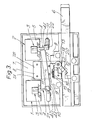
- the mechanism shown in Figures 1-3 includes two bistable electromechanical actuators 1 and 2.
- Each actuator comprises a magnetising coil 3 within which is pivoted an actuating member 4.
- a rectangular horseshoe permanent magnet 5 surrounds the coil 3, with the actuating member 4 extending through the gap between the magnet poles Pl and P2. That part of each actuating member 4 which extends within the corresponding coil 3 and between the associated permanent magnet poles, is made from a piece of magnetisable material such as heat-treated Vicalloy.
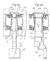
- FIG. 4a and 4b An example of the construction of an actuator for use in this release mechanism is shown in Figures 4a and 4b.
- a bar 4A (which may be laminated) of Vicalloy is fitted at one end with a plastics cap 4B by which it is pivotally suspended in a pair of recesses 3B formed inside the coil bobbin 3A.
- the bar 4A extends out of the bobbin 3A to lie between the poles of the associated field magnet 5 and at its lower end is fitted with a plastics tip piece 4C.
- This tip piece provides an abutment surface 4D and a mask portion 4E, for purposes to be described hereafter.
- the actuator is assembled by passing the Vicalloy bar 4A with its cap 4B through the top of the coil bobbin 3A and snapping on the tip piece 4C.
- the coil is then assembled to the magnet 5 which retains the actuating member against ejection through the top of the bobbin.
- the actuating members 4 can be flipped between two positions (as indicated by comparing their positions in Figures 1 and 2) in response to pulses of electricity passed through the associated coils 3 in opposite directions. For example, if it is assumed that the magnet pole PI in actuator 1 is a North and P2 a South, then if an electrical pulse is sent through the associated coil 3 in the direction such as to induce a North pole at the top end of the Vicalloy element 4A within the coil and a South pole at the bottom end of that element between the poles Pl and P2, then the element will be attracted by pole Pl and repelled by pole P2 so as to pivot the actuating member into the position in which it is shown in Figure 1.
- the remanence of the element 4A is sufficient to keep the actuating member in that position until an electrical pulse is sent through the coil 3 in the opposite direction, whereupon the induced polarity of the element 4A is reversed so that its end between the poles PI and P2 now becomes a North, and it will be influenced oppositely by the permanent magnet poles to pivot the actuating member into the position in which it is shown in Figure 2.
- the actuating member of actuator 2 can be influenced to move between its two positions in like manner.
- each actuator coil 3 receives pulses from a respective channel of a dual channel electronic timing circuit, schematically illustrated in Figure 5.
- This circuit contains two CMOS microprocessors 100 controlling respective driver circuits 101 for the actuators, and which can be programmed simultaneously by a common key pad 102 to provide selected daily "on guard” (ie locked) and "off guard” (ie unlocked) periods.
- each microprocessor is equipped with a standard 32KHz watch crystal 102.
- the microprocessors also drive respective liquid crystal displays 104 to indicate the next programmed "on guard” and “off guard” times together with other indications, warnings and prompts appropriate to the setting and operation of the lock, the details of which do not form part of the present invention. Power for all of the functions of the control circuits, actuators and displays is provided by batteries 105.
- the illustrated lock is assumed to be fitted to the door of a bank vault.
- a bar 6 is secured to one of the boltstraps (not shown) of the main boltwork of the door so as to slide horizontally through the lockcase 7 as the door bolts are thrown and withdrawn.
- this shows the bar 6 in the position in which the door bolts are thrown, withdrawal of those bolts requiring movement of the bar to the left as viewed in that figure.
- the lock includes a vertically-sliding bolt 8, mounted between the actuators 1 and 2, to obstruct withdrawal of the bar 6 (and thus block the door bolts) during "on guard" periods.
- This lock bolt is borne in a guideway 7A in the lockcase and extends between two relatively massive pillars 9, and is biased downwardly by its own weight.
- a balance beam 10 is mounted to the bolt 8 through a central pivot 11, so as normally to lie perpendicularly to the path of movement of the bolt. In the Figure 1 condition this beam rests on the tops of the pillars 9 to define the limiting obstructing position of the bolt 8.
- This Figure also shows that when the actuators 1 and 2 are pulsed to their "on guard” positions the surfaces 4D of the actuator tips lie directly in front of respective ends of the beam 10 (in the sense of the upward, releasing movement of the bolt 8); the mask portions 4E of the actuator tips are, however, offset so as to overlap the beam 10. When the actuators 1 and 2 are pulsed to their "off guard” positions their members 4 pivot away from one another (as shown in Figure 2), to lie clear of the beam 10.
- a lever arm 12 Extending from the bottom of the bolt 8 is a lever arm 12 , this being provided on a snib 13 pivoted to the bolt at 1 4.
- a plunger 15 biased by a spring 16 acts on another arm 17 of this snib to urge it to the illustrated rotary position against a stop 18.
- the spring snib 13 serves to limit the force which can be applied through the bolt against the actuating members 4 when "on guard", to prevent damage to the actuators if the bar 6 is forced.
- the distance through which the bar 6 retracts from its normal thrown position to bring the face 20 up against the bolt 8 is insufficient to permit release of the door's boltwork; typically this distance may be 6mm where the total throw of the bar is in the range 35-50mm.
- Figure 3 in fact shows the mechanism at the point where the lever arm 12 has just ridden out of the notch 19, in which condition the bolt 8 has just risen clear of the bar face 20 and been arrested by the stop face 7B, further retraction of the bar 6 causing the snib 13 to rotate against the spring 16 as further upward movement of the bolt is limited.
- actuator 1 operates and actuator 2 fails is equivalent, with the beam 10 pivoting the other way.
- the positions of the actuating members 4 are monitored by respective transducers 21. These may comprise photoelectric devices having a slot 22 (see Figure 3) across which an infra red light beam is transmitted and detected, the mask 4E of the associated actuating member extending into the slot to interrupt the beam when in the "off guard" position.
- each actuator coil 3 comprises 750 turns of 0.14mm wire, wound as 54 turns per layer and 14 layers, giving a total resistance of 25 ohms; the field strength in the centre of the gap in each permanent magnet 5 is 750 gaus; and the electrical energy in each magnetising pulse is 100 milli-Joules, supplied by discharging a 220 micro-Farad capacitor charged to 30 volts.
- the maximum magnetising force occurs 2 milliseconds after switching, the respective microprocessor supplying a control pulse of 20 milliseconds for each magnetisation. This develops a force of 15 grams attraction and 5 grams repulsion as measured at the tip of a 20mm long Vicalloy element 4A. It is estimated that a dual-channel timelock employing actuators 1 and 2 of this nature can be constructed to run for periods in excess of two years, with four changes of state for each actuator daily, solely from the power provided from eg six type MN1500 manganese alkaline batteries.
Landscapes
- Physics & Mathematics (AREA)
- General Physics & Mathematics (AREA)
- Electromagnetism (AREA)
- Lock And Its Accessories (AREA)
- Electromagnets (AREA)
Applications Claiming Priority (2)
| Application Number | Priority Date | Filing Date | Title |
|---|---|---|---|
| GB838313142A GB8313142D0 (en) | 1983-05-12 | 1983-05-12 | Electro-mechanical actuators and lock mechanisms |
| GB8313142 | 1983-05-12 |
Publications (2)
| Publication Number | Publication Date |
|---|---|
| EP0125813A2 true EP0125813A2 (fr) | 1984-11-21 |
| EP0125813A3 EP0125813A3 (fr) | 1985-06-26 |
Family
ID=10542638
Family Applications (1)
| Application Number | Title | Priority Date | Filing Date |
|---|---|---|---|
| EP84302672A Ceased EP0125813A3 (fr) | 1983-05-12 | 1984-04-19 | Mécanisme de fermeture |
Country Status (6)
| Country | Link |
|---|---|
| US (1) | US4850623A (fr) |
| EP (1) | EP0125813A3 (fr) |
| AU (1) | AU2763184A (fr) |
| CA (1) | CA1246632A (fr) |
| GB (2) | GB8313142D0 (fr) |
| NZ (1) | NZ208034A (fr) |
Cited By (2)
| Publication number | Priority date | Publication date | Assignee | Title |
|---|---|---|---|---|
| EP0256430A1 (fr) * | 1986-08-20 | 1988-02-24 | Relhor S.A. | Dispositif pour annuler en cas de panne l'interdiction d'ouverture d'une serrure à ouverture conditionnelle |
| US20220220772A1 (en) * | 2018-08-13 | 2022-07-14 | Montajes Electronicos Dorcas, S.L. | Lock device |
Families Citing this family (13)
| Publication number | Priority date | Publication date | Assignee | Title |
|---|---|---|---|---|
| US4875351A (en) * | 1988-08-19 | 1989-10-24 | Sargent & Greenleaf, Inc. | Electronic time lock |
| IT1238550B (it) * | 1990-04-11 | 1993-08-18 | Italiana Serrature Affini | Dispositivo per l'azionamento dello scrocco in serrature con funzionamento a scheda magnetica. |
| FR2661938A1 (fr) * | 1990-05-14 | 1991-11-15 | Ciposa Microtech | Dispositif de commande de l'ouverture temporisee d'une serrure. |
| US5603234A (en) * | 1994-05-13 | 1997-02-18 | Diebold, Incorporated | Multiple lock assembly |
| AUPM920394A0 (en) * | 1994-11-01 | 1994-11-24 | Technosearch Pty. Limited | Remote lock control means |
| US6006561A (en) * | 1997-05-07 | 1999-12-28 | Mas-Hamilton Group, Inc. | Electronic reset for solenoid activated control in an electronic lock |
| US6825753B2 (en) * | 1999-01-11 | 2004-11-30 | Salvatore J. Cardinale | Time-lock box |
| US6902214B2 (en) * | 2001-06-19 | 2005-06-07 | Jerry R. Smith | Electromechanical locking method and device |
| CN102016203B (zh) * | 2008-03-05 | 2013-11-27 | 诺克N’洛克有限公司 | 凸轮锁 |
| EP3040499B1 (fr) * | 2013-05-30 | 2018-10-24 | Sunsmilet's Corporation | Mécanisme de verrouillage et coffre de sécurité utilisant ledit mécanisme |
| AU2016255582A1 (en) | 2015-04-30 | 2017-09-28 | Bryan Michael Risi | Actuating assembly for a latching system |
| US11898376B2 (en) | 2021-09-23 | 2024-02-13 | George Condorodis | Door and window securing apparatus and method |
| US11447983B1 (en) | 2021-09-23 | 2022-09-20 | George Condorodis | Door and window securing apparatus and method |
Family Cites Families (7)
| Publication number | Priority date | Publication date | Assignee | Title |
|---|---|---|---|---|
| DE74343C (de) * | F. SOHL, in Firma FRITZ SOHL & SINGELMANN, in Magdeburg, Kaiserstr. 90 | Elektrische Controlvorrichtung und Sicherung für Thürverschlüsse | ||
| US1361317A (en) * | 1920-02-18 | 1920-12-07 | Dulczewski Sigmund | Burglar-lock |
| DE503560C (de) * | 1928-03-18 | 1930-07-24 | Alfred Zumkeller | Elektrisches Schloss mit zweiteiliger Falle |
| FR1274561A (fr) * | 1960-09-12 | 1961-10-27 | Vente D Aimants Allevard Ugine | Procédé de commande et de contrôle d'un flux magnétique, dispositif pour sa mise en oeuvre, ses applications et les produits ainsi obtenus |
| FR2174438A5 (fr) * | 1972-03-03 | 1973-10-12 | Beharelle Bernard | |
| US3907343A (en) * | 1973-11-23 | 1975-09-23 | Charles M Goodwin | Door locking structure |
| GB1538297A (en) * | 1975-11-21 | 1979-01-17 | Access Control Syst | Door lock apparatus |
-
1983
- 1983-05-12 GB GB838313142A patent/GB8313142D0/en active Pending
-
1984
- 1984-04-19 EP EP84302672A patent/EP0125813A3/fr not_active Ceased
- 1984-05-02 NZ NZ208034A patent/NZ208034A/en unknown
- 1984-05-03 AU AU27631/84A patent/AU2763184A/en not_active Abandoned
- 1984-05-03 GB GB08411427A patent/GB2142374B/en not_active Expired
- 1984-05-08 CA CA000453761A patent/CA1246632A/fr not_active Expired
- 1984-05-11 US US06/609,371 patent/US4850623A/en not_active Expired - Fee Related
Cited By (4)
| Publication number | Priority date | Publication date | Assignee | Title |
|---|---|---|---|---|
| EP0256430A1 (fr) * | 1986-08-20 | 1988-02-24 | Relhor S.A. | Dispositif pour annuler en cas de panne l'interdiction d'ouverture d'une serrure à ouverture conditionnelle |
| FR2603059A1 (fr) * | 1986-08-20 | 1988-02-26 | Relhor Sa | Dispositif pour annuler en cas de panne l'interdiction d'ouverture d'une serrure a ouverture conditionnelle |
| US4944170A (en) * | 1986-08-20 | 1990-07-31 | Relhor S.A. | Device for lifting a time ban on the actuation of a mechanism in a conditional-opening locking system in the event of a breakdown |
| US20220220772A1 (en) * | 2018-08-13 | 2022-07-14 | Montajes Electronicos Dorcas, S.L. | Lock device |
Also Published As
| Publication number | Publication date |
|---|---|
| AU2763184A (en) | 1984-11-15 |
| GB8313142D0 (en) | 1983-06-15 |
| NZ208034A (en) | 1987-05-29 |
| US4850623A (en) | 1989-07-25 |
| GB8411427D0 (en) | 1984-06-06 |
| CA1246632A (fr) | 1988-12-13 |
| GB2142374B (en) | 1987-03-25 |
| GB2142374A (en) | 1985-01-16 |
| EP0125813A3 (fr) | 1985-06-26 |
Similar Documents
| Publication | Publication Date | Title |
|---|---|---|
| US4850623A (en) | Locking mechanisms | |
| US5893283A (en) | Solenoid controlled bolt control for an electronic lock | |
| US6178791B1 (en) | Electronic reset for solenoid activated control in an electronic lock | |
| US2931953A (en) | Magnetically controlled lock and switch | |
| DE10230344B3 (de) | Manipulationssichere Elektromagnetanordnung, elektronischer Schließzylinder und Verfahren zum Verhindern einer Manipulation einer Elektromagnetanordnung | |
| FI80751C (fi) | Anordning foer elektromagnetisk laosning av en laoscylinder vid ett mekaniskt/elektroniskt laossystem. | |
| EP0260860B1 (fr) | Mécanisme pour serrure | |
| US20070137326A1 (en) | Movement transmission device and method | |
| JP2011523687A (ja) | 微小電力で動作するパッシブ電子シリンダー錠 | |
| US6857671B2 (en) | Locking device for a door | |
| US6094953A (en) | Electrically controlled slidebolt lock | |
| FI92513B (fi) | Lukko, jossa on sähkömekaaninen vapautusmekanismi | |
| RU2226299C2 (ru) | Устройство обнаружения вскрытия измерительного прибора | |
| WO2006016826A2 (fr) | Serrure amelioree | |
| GB2212548A (en) | Electrically released locking device | |
| JPS60229188A (ja) | 硬貨処理装置 | |
| PL166258B1 (pl) | Urządzenie zabezpieczające zasuwę przed niepowołanym otwarciem | |
| RU2614198C1 (ru) | Устройство для хранения и выдачи предметов | |
| JPS62289639A (ja) | 電磁駆動ジヤカ−ド制御装置 | |
| US4774509A (en) | Reset device for indicator | |
| HK1015430A (en) | Solenoid controlled bolt control for an electronic lock | |
| GB2114204A (en) | A remotely actuable time lock | |
| IL295760B1 (en) | Deposit lock system and method for operating a deposit lock system for a loan object | |
| HK1012200A (en) | Electronic reset for solenoid activated control in an electronic lock | |
| JPH04118481A (ja) | ロッカ用電子錠 |
Legal Events
| Date | Code | Title | Description |
|---|---|---|---|
| PUAI | Public reference made under article 153(3) epc to a published international application that has entered the european phase |
Free format text: ORIGINAL CODE: 0009012 |
|
| AK | Designated contracting states |
Designated state(s): AT BE CH DE FR IT LI LU NL SE |
|
| PUAL | Search report despatched |
Free format text: ORIGINAL CODE: 0009013 |
|
| AK | Designated contracting states |
Designated state(s): AT BE CH DE FR IT LI LU NL SE |
|
| 17P | Request for examination filed |
Effective date: 19851007 |
|
| 17Q | First examination report despatched |
Effective date: 19860630 |
|
| RAP1 | Party data changed (applicant data changed or rights of an application transferred) |
Owner name: CHUBB & SON'S LOCK AND SAFE COMPANY LIMITED |
|
| STAA | Information on the status of an ep patent application or granted ep patent |
Free format text: STATUS: THE APPLICATION HAS BEEN REFUSED |
|
| 18R | Application refused |
Effective date: 19871115 |
|
| RIN1 | Information on inventor provided before grant (corrected) |
Inventor name: LUCKETT, NICHOLAS GEORGE Inventor name: FRANKLIN, ROY WALTER |