EP0125820A2 - Disposition de surveillance pour l'allumage à étincelles d'une turbine à gaz - Google Patents
Disposition de surveillance pour l'allumage à étincelles d'une turbine à gaz Download PDFInfo
- Publication number
- EP0125820A2 EP0125820A2 EP84302753A EP84302753A EP0125820A2 EP 0125820 A2 EP0125820 A2 EP 0125820A2 EP 84302753 A EP84302753 A EP 84302753A EP 84302753 A EP84302753 A EP 84302753A EP 0125820 A2 EP0125820 A2 EP 0125820A2
- Authority
- EP
- European Patent Office
- Prior art keywords
- signals
- signal
- arrangement
- indicating
- filter
- Prior art date
- Legal status (The legal status is an assumption and is not a legal conclusion. Google has not performed a legal analysis and makes no representation as to the accuracy of the status listed.)
- Granted
Links
Images


Classifications
-
- F—MECHANICAL ENGINEERING; LIGHTING; HEATING; WEAPONS; BLASTING
- F02—COMBUSTION ENGINES; HOT-GAS OR COMBUSTION-PRODUCT ENGINE PLANTS
- F02C—GAS-TURBINE PLANTS; AIR INTAKES FOR JET-PROPULSION PLANTS; CONTROLLING FUEL SUPPLY IN AIR-BREATHING JET-PROPULSION PLANTS
- F02C7/00—Features, components parts, details or accessories, not provided for in, or of interest apart form groups F02C1/00 - F02C6/00; Air intakes for jet-propulsion plants
- F02C7/26—Starting; Ignition
- F02C7/264—Ignition
- F02C7/266—Electric
-
- F—MECHANICAL ENGINEERING; LIGHTING; HEATING; WEAPONS; BLASTING
- F02—COMBUSTION ENGINES; HOT-GAS OR COMBUSTION-PRODUCT ENGINE PLANTS
- F02P—IGNITION, OTHER THAN COMPRESSION IGNITION, FOR INTERNAL-COMBUSTION ENGINES; TESTING OF IGNITION TIMING IN COMPRESSION-IGNITION ENGINES
- F02P15/00—Electric spark ignition having characteristics not provided for in, or of interest apart from, groups F02P1/00 - F02P13/00 and combined with layout of ignition circuits
- F02P15/001—Ignition installations adapted to specific engine types
- F02P15/003—Layout of ignition circuits for gas turbine plants
-
- F—MECHANICAL ENGINEERING; LIGHTING; HEATING; WEAPONS; BLASTING
- F02—COMBUSTION ENGINES; HOT-GAS OR COMBUSTION-PRODUCT ENGINE PLANTS
- F02P—IGNITION, OTHER THAN COMPRESSION IGNITION, FOR INTERNAL-COMBUSTION ENGINES; TESTING OF IGNITION TIMING IN COMPRESSION-IGNITION ENGINES
- F02P17/00—Testing of ignition installations, e.g. in combination with adjusting; Testing of ignition timing in compression-ignition engines
- F02P17/12—Testing characteristics of the spark, ignition voltage or current
Definitions
- This invention relates to a monitoring arrangement for a spark ignition system for starting a gas turbine engine.
- gas turbine engines are commonly ignited by a spark device which is energised by a relatively high voltage from a supply unit. It is required to monitor operation of the spark igniter device. Detection of discharge current is unsatisfactory since the possibility of insulation breakdown other than at the head of the spark device cannot be excluded. Additionally, any monitoring arrangement must be able to withstand the temperature and other adverse environmental conditions adjacent the combustion chamber of a gas turbine engine.
- a common type of unit for supplying the ignition voltage includes components which act as a resonant circuit, whereby the discharge current across the igniter is in the form of a damped oscillation whose frequency is known in advance.
- a sonic transducer acoustically coupled to the spark igniter device is used to pick up the sound of the discharge across the end of the device.
- an arrangement for monitoring operation of a spark ignition system in which the discharge current oscillates at a known frequency comprises a sonic transducer adapted to be coupled acoustically to a spark igniter in said system, and means for detecting the presence of a signal from said transducer at a frequency substantially equal to that of said discharge current.
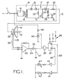
- an ignition control unit 10 is responsive to application of a 28v d.c. supply by means of a switch 11, to provide a high voltage on a line 12 to a spark igniter device 13 mounted in a wall of a combustion chamber 14 of a gas turbine engine.
- the unit 10 is of the general type disclosed in U.K. Patent 896161 and includes an oscillator circuit 15 coupled through a transformer 16 to an output circuit 17.
- the output circuit 17 includes two rectifying diodes 18, a 3KV discharge gap 19 and a 40-turn winding 20 connected in series between one end of the secondary of the transformer 16 and the line 12. The other end of the transformer secondary is connected to an earth rail 21.
- a 10 megohm bleed resistor 22 and a 0.6 ⁇ F capacitance 23 are connected in parallel between the rail 21 and the input of the discharge gap 19.
- the output side of the discharge gap 19 is connected to the rail 21 through a 9-turn coil 24 and a 0.03fLF capacitor 25 arranged in series.
- a 2K ohm resistor 26 is connected in parallel with the capacitor 25.
- the coils 20, 24 combine to provide an autotransformer by means of which the voltage on the line 12 may be raised.
- the capacitor 23 With the oscillator circuit 15 energised the capacitor 23 is charged through the diodes 18 until the discharge gap 19 breaks down at 3KV. Current flow through the coil 24 and capacitor 25 causes the autotransformer to raise the voltage on line 12 to provide an ignition pulse of 11KV and 20 nano seconds duration on the line 12. The foregoing process is repeated so long as the switch 11 remains closed, whereby igniter pulses are repeatedly provided on the line 12, typically at intervals of 0.75 seconds.
- the spark igniter 13 If the spark igniter 13 is operating satisfactorily a discharge will be initiated by each pulse on the line 12..
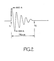
- the coil 20 and the capacitor 23 act as a series resonant circuit, and the discharge current across the tip of the igniter 13 takes the form of a damped ocillation of constant frequency, as shown in Figure 2, the duration of the discharge typically being 75 ⁇ seconds.
- the frequency of the oscillation is dependent on the values of the coil 20 and the capacitor 23, and in the present case is between 66 and 69 KHz.
- the lines 31, 32 are connected to the input terminals of a bandpass filter amplifier 33, to provide an output pulse on a line 34 in response only to signals in the, region of 66-69 KHz on the lines 31, 32.
- Pulses on the line 34 are supplied through a diode 35 to an input of an-AND gate 36.
- the diode 35 co-operates with a capacitor 47 to rectify the output signals from the amplifier 33.
- the other input of the gate 36 is supplied with a signal derived from the 28 volt input to the control arrangement 10, through a dropping resistor 45, this signal being maintained at a required level by a zener diode 46.
- the gate 36 thus provides, an ouput signal only when the switch 11 is closed and the spark igniter 13 discharges, and this output is applied to a monostable multivibrator 37 of the type available from Texas Instruments under the designation SN54121 whose operating time is set by a resistor and capacitor arrangement 38 to be longer than the .75 second repetition period of the unit 10.
- the monostable 37 provides a signal at its Q output in response to an output signal from the gate 36, and the Q output signal is maintained so long as the switch 11 is closed and the igniter 13 is operating correctly. In all other conditions the monostable 37 provides a signal at its Q output.
- the Q and Q signals are applied via respective lines 39, 40 and amplifiers 41, 42 to indicator devices 43, 44 which in the present example are light-emitting diodes.
- Device 44 is thus energised at all times in which the ignition system is not operated, and indicates that the detector arrangement logic is functioning correctly.
- Device 43 is energised only when the ignition system is energised through the switch 11 and results in an ignition discharge at the device 13.
- FIG. 3 The arrangement shown in Figure 3 is generally similar to that shown in Figure 1, corresponding elements having identical reference numbers.
- a circuit 48 is substituted for the diode 35 and capacitor 47 shown in Figure 1, and in addition to rectifying the output signals from the filter amplifier 33, both shapes the rectified signals and extends their duration from the 75 u seconds of the discharge time.
- the output signals from the circuit 48 are applied on a line 49 to one input, of the AND gate 36.
- Light resulting from operation of the discharge gap 19 is supplied through a fibre optic element 50 to a known type of device 51 which provides electrical signals on a line 52 in response to discharge across the gap 19.
- the signals on line 52 are applied to an amplifier 53 and thence through a circuit 54 similar to the circuit 48.
- the output signals from circuit 54 are applied on a line 55 to a second input of the AND gate 36.
- the components 45, 46 shown in Figure 1, which provide an indication that the switch 11 is closed, are omitted in the embodiment shown in Figure 3, but in a modified form of that embodiment may be included and provide a signal to a third input of the AND gate 36.
- the signals on lines 49 and 55 substantially coincide when the ignition system is operating correctly, so that in this condition the device 43 is energised. In all other conditions, including those in which signals on line 49 originate from spurious vibrations, no indication is given by the device 43.
- FIG. 4 The arrangement shown in Figure 4 is also generally similar to that of Figure. 1, corresponding elements being identically numbered.
- a circuit 60 is substituted for the diode 35 and capacitor 47, and performs the functions of rectifying, shaping and extending the signals from the filter amplifier 33.
- Light from the discharge gap 19 passes through a fibre optic element 61 to a device 62 identical with the device 51 in Figure 3.
- Electrical signals from the device 62 are amplified, rectified, shaped and extended by circuits 63, 64 corresponding to the amplifier 53 and circuit 54 respectively in Figure 3.
- Signals from the circuit 64 are applied to a monostable arrangement 65 corresponding to the arrangement 37, 38.
- Signals from the Q outputs of the monostable arrangements 37, 38 and 65 are supplied to an AND gate 66 whose output signals are applied on the line 39 to the amplifier 41.
- Input signals to the gate 66 are substantially coincident when the ignition system is operating correctly, in which condition the gate 66 provides an output signal to energise the indicator device 43, as described above. In all other conditions the device 44 is energised.
Landscapes
- Engineering & Computer Science (AREA)
- Chemical & Material Sciences (AREA)
- Combustion & Propulsion (AREA)
- Mechanical Engineering (AREA)
- General Engineering & Computer Science (AREA)
- Ignition Installations For Internal Combustion Engines (AREA)
Applications Claiming Priority (2)
| Application Number | Priority Date | Filing Date | Title |
|---|---|---|---|
| GB8312965 | 1983-05-11 | ||
| GB838312965A GB8312965D0 (en) | 1983-05-11 | 1983-05-11 | Monitoring arrangement |
Publications (3)
| Publication Number | Publication Date |
|---|---|
| EP0125820A2 true EP0125820A2 (fr) | 1984-11-21 |
| EP0125820A3 EP0125820A3 (en) | 1985-11-21 |
| EP0125820B1 EP0125820B1 (fr) | 1988-06-15 |
Family
ID=10542548
Family Applications (1)
| Application Number | Title | Priority Date | Filing Date |
|---|---|---|---|
| EP84302753A Expired EP0125820B1 (fr) | 1983-05-11 | 1984-04-24 | Disposition de surveillance pour l'allumage à étincelles d'une turbine à gaz |
Country Status (5)
| Country | Link |
|---|---|
| US (1) | US4636777A (fr) |
| EP (1) | EP0125820B1 (fr) |
| JP (1) | JPS59224423A (fr) |
| DE (1) | DE3472136D1 (fr) |
| GB (1) | GB8312965D0 (fr) |
Cited By (7)
| Publication number | Priority date | Publication date | Assignee | Title |
|---|---|---|---|---|
| EP0226302A3 (en) * | 1985-11-27 | 1988-07-20 | Lucas Industries Public Limited Company | Method and apparatus for monitoring operation of a spark ignition device in a gas turbine engine |
| EP0468253A3 (fr) * | 1990-07-26 | 1994-01-05 | Unison Ind Inc | |
| EP0501152A3 (en) * | 1991-02-27 | 1994-07-06 | Westinghouse Electric Corp | Apparatus for ignition diagnosis in a combustion turbine |
| US5523691A (en) * | 1990-07-26 | 1996-06-04 | Unison Industries Limited Partnership | Diagnostic device for gas turbine ignition system |
| US6670777B1 (en) | 2002-06-28 | 2003-12-30 | Woodward Governor Company | Ignition system and method |
| US7355300B2 (en) | 2004-06-15 | 2008-04-08 | Woodward Governor Company | Solid state turbine engine ignition exciter having elevated temperature operational capability |
| EP3260778A3 (fr) * | 2016-06-21 | 2018-03-07 | John Zink Company, L.L.C. | Système et procédé de détection d'étincelle électrique |
Families Citing this family (5)
| Publication number | Priority date | Publication date | Assignee | Title |
|---|---|---|---|---|
| US5245252A (en) | 1988-11-15 | 1993-09-14 | Frus John R | Apparatus and method for providing ignition to a turbine engine |
| US5103214A (en) * | 1990-09-07 | 1992-04-07 | Minnesota Mining And Manufacturing Company | Auxiliary alarm |
| US7242195B2 (en) * | 2004-02-10 | 2007-07-10 | General Electric Company | Integral spark detector in fitting which supports igniter in gas turbine engine |
| US7191084B2 (en) * | 2005-04-20 | 2007-03-13 | General Electric Company | Method and apparatus for gas turbine engine ignition systems |
| US9822708B2 (en) * | 2014-05-06 | 2017-11-21 | Woodward, Inc. | Igniter event conductor for conducting igniter events from a combustion chamber to a sensor |
Family Cites Families (10)
| Publication number | Priority date | Publication date | Assignee | Title |
|---|---|---|---|---|
| US2659881A (en) * | 1950-04-26 | 1953-11-17 | Combustion Eng | Detection of stoppage in the flow of divided material |
| US3016457A (en) * | 1957-09-30 | 1962-01-09 | Gen Railway Signal Co | Detection means for improperly lubricated journals |
| GB896161A (en) * | 1959-05-19 | 1962-05-09 | Rotax Ltd | Ignition systems |
| US3895344A (en) * | 1970-02-12 | 1975-07-15 | Us Navy | Vehicle detection system and method of operation |
| US3665445A (en) * | 1970-12-22 | 1972-05-23 | Scient Security Systems Inc | Detection system |
| US4307387A (en) * | 1979-02-23 | 1981-12-22 | Elliott Brothers (London) Limited | Vibration-responsive intruder alarm system |
| US4292591A (en) * | 1979-05-09 | 1981-09-29 | Doss James D | Ignition performance monitor for permanent installation |
| US4279027A (en) * | 1979-09-13 | 1981-07-14 | Honeywell Inc. | Acoustic sensor |
| US4417235A (en) * | 1981-03-24 | 1983-11-22 | Del Grande Donald J | Audible alarm network |
| US4473821A (en) * | 1982-02-12 | 1984-09-25 | Ensco Inc. | Personal acoustic alarm system |
-
1983
- 1983-05-11 GB GB838312965A patent/GB8312965D0/en active Pending
-
1984
- 1984-04-24 DE DE8484302753T patent/DE3472136D1/de not_active Expired
- 1984-04-24 EP EP84302753A patent/EP0125820B1/fr not_active Expired
- 1984-05-02 US US06/606,241 patent/US4636777A/en not_active Expired - Fee Related
- 1984-05-11 JP JP59093059A patent/JPS59224423A/ja active Pending
Cited By (9)
| Publication number | Priority date | Publication date | Assignee | Title |
|---|---|---|---|---|
| EP0226302A3 (en) * | 1985-11-27 | 1988-07-20 | Lucas Industries Public Limited Company | Method and apparatus for monitoring operation of a spark ignition device in a gas turbine engine |
| EP0468253A3 (fr) * | 1990-07-26 | 1994-01-05 | Unison Ind Inc | |
| US5343154A (en) * | 1990-07-26 | 1994-08-30 | Unison Industries, Inc. | Diagnostic device for gas turbine ignition system |
| US5523691A (en) * | 1990-07-26 | 1996-06-04 | Unison Industries Limited Partnership | Diagnostic device for gas turbine ignition system |
| US5675257A (en) * | 1990-07-26 | 1997-10-07 | Unison Industries Limited Partnership | Diagnostic device for gas turbine ignition system |
| EP0501152A3 (en) * | 1991-02-27 | 1994-07-06 | Westinghouse Electric Corp | Apparatus for ignition diagnosis in a combustion turbine |
| US6670777B1 (en) | 2002-06-28 | 2003-12-30 | Woodward Governor Company | Ignition system and method |
| US7355300B2 (en) | 2004-06-15 | 2008-04-08 | Woodward Governor Company | Solid state turbine engine ignition exciter having elevated temperature operational capability |
| EP3260778A3 (fr) * | 2016-06-21 | 2018-03-07 | John Zink Company, L.L.C. | Système et procédé de détection d'étincelle électrique |
Also Published As
| Publication number | Publication date |
|---|---|
| EP0125820B1 (fr) | 1988-06-15 |
| EP0125820A3 (en) | 1985-11-21 |
| JPS59224423A (ja) | 1984-12-17 |
| DE3472136D1 (en) | 1988-07-21 |
| GB8312965D0 (en) | 1983-06-15 |
| US4636777A (en) | 1987-01-13 |
Similar Documents
| Publication | Publication Date | Title |
|---|---|---|
| EP0125820A2 (fr) | Disposition de surveillance pour l'allumage à étincelles d'une turbine à gaz | |
| US5472336A (en) | Flame rectification sensor employing pulsed excitation | |
| US5599180A (en) | Circuit arrangement for flame detection | |
| US4760341A (en) | Method and apparatus for monitoring operation of a spark ignition device in a gas turbine engine | |
| EP3140533B1 (fr) | Diagnostic d'allumage localisé | |
| US4450499A (en) | Flare ignition system | |
| US2291045A (en) | Synchronizing arrangement for detonation detectors | |
| SE9102799L (sv) | Direkttaendsystem med individuell knackdetektionssensor | |
| KR900700741A (ko) | 내연기관의 연소관찰 방법 및 그 장치 | |
| US4488528A (en) | System for controlling the ignition timing of a combustion engine | |
| US5194813A (en) | Spark ignition analyzer | |
| US3182648A (en) | Speed responsive switching apparatus | |
| US4643023A (en) | Vibration testing apparatus | |
| EP0344349A1 (fr) | Détection d'un défaut d'allumage dans les moteurs à allumage par étincelles | |
| RU2614388C2 (ru) | Устройство контроля емкостной системы зажигания двигателей летательных аппаратов | |
| JP2834574B2 (ja) | 内燃機関の全電子式点火装置 | |
| JPS6368774A (ja) | 内燃機関用スパ−クプラグのプレイグニシヨン検出装置 | |
| US4423624A (en) | Diesel timing light | |
| EP0094945A1 (fr) | Dispostif de controle d'injecteur | |
| EP4382741B1 (fr) | Systèmes d'allumage de moteur et procédés de commande associés | |
| RU2087741C1 (ru) | Способ поджига рабочей смеси в цилиндре двигателя внутреннего сгорания с одновременной регистрацией пропусков воспламенения и система для его осуществления | |
| US6317645B1 (en) | Suction-air system of a textile machine | |
| US5957679A (en) | Gas fireplace burner control system | |
| RU2680724C1 (ru) | Способ контроля емкостной системы зажигания двигателей летательных аппаратов | |
| US5682860A (en) | Device and method for ignition detection |
Legal Events
| Date | Code | Title | Description |
|---|---|---|---|
| PUAI | Public reference made under article 153(3) epc to a published international application that has entered the european phase |
Free format text: ORIGINAL CODE: 0009012 |
|
| AK | Designated contracting states |
Designated state(s): DE FR GB IT SE |
|
| PUAL | Search report despatched |
Free format text: ORIGINAL CODE: 0009013 |
|
| RHK1 | Main classification (correction) |
Ipc: F02C 7/266 |
|
| AK | Designated contracting states |
Designated state(s): DE FR GB IT SE |
|
| 17P | Request for examination filed |
Effective date: 19860508 |
|
| 17Q | First examination report despatched |
Effective date: 19870109 |
|
| GRAA | (expected) grant |
Free format text: ORIGINAL CODE: 0009210 |
|
| AK | Designated contracting states |
Kind code of ref document: B1 Designated state(s): DE FR GB IT SE |
|
| PG25 | Lapsed in a contracting state [announced via postgrant information from national office to epo] |
Ref country code: SE Effective date: 19880630 |
|
| REF | Corresponds to: |
Ref document number: 3472136 Country of ref document: DE Date of ref document: 19880721 |
|
| ITF | It: translation for a ep patent filed | ||
| ET | Fr: translation filed | ||
| PLBE | No opposition filed within time limit |
Free format text: ORIGINAL CODE: 0009261 |
|
| STAA | Information on the status of an ep patent application or granted ep patent |
Free format text: STATUS: NO OPPOSITION FILED WITHIN TIME LIMIT |
|
| 26N | No opposition filed | ||
| ITTA | It: last paid annual fee | ||
| PGFP | Annual fee paid to national office [announced via postgrant information from national office to epo] |
Ref country code: FR Payment date: 19920408 Year of fee payment: 9 |
|
| PGFP | Annual fee paid to national office [announced via postgrant information from national office to epo] |
Ref country code: GB Payment date: 19920410 Year of fee payment: 9 |
|
| PGFP | Annual fee paid to national office [announced via postgrant information from national office to epo] |
Ref country code: DE Payment date: 19920521 Year of fee payment: 9 |
|
| PG25 | Lapsed in a contracting state [announced via postgrant information from national office to epo] |
Ref country code: GB Effective date: 19930424 |
|
| GBPC | Gb: european patent ceased through non-payment of renewal fee |
Effective date: 19930424 |
|
| PG25 | Lapsed in a contracting state [announced via postgrant information from national office to epo] |
Ref country code: FR Effective date: 19931229 |
|
| PG25 | Lapsed in a contracting state [announced via postgrant information from national office to epo] |
Ref country code: DE Effective date: 19940101 |
|
| REG | Reference to a national code |
Ref country code: FR Ref legal event code: ST |