EP0125980A2 - Kühl- und Verflüssigungsverfahren und Anlage für mindestens ein Gas mit niedrigem Siedepunkt, wie z.B. Erdgas - Google Patents
Kühl- und Verflüssigungsverfahren und Anlage für mindestens ein Gas mit niedrigem Siedepunkt, wie z.B. Erdgas Download PDFInfo
- Publication number
- EP0125980A2 EP0125980A2 EP84400906A EP84400906A EP0125980A2 EP 0125980 A2 EP0125980 A2 EP 0125980A2 EP 84400906 A EP84400906 A EP 84400906A EP 84400906 A EP84400906 A EP 84400906A EP 0125980 A2 EP0125980 A2 EP 0125980A2
- Authority
- EP
- European Patent Office
- Prior art keywords
- aforementioned
- refrigerant
- main
- vapor
- pressure
- Prior art date
- Legal status (The legal status is an assumption and is not a legal conclusion. Google has not performed a legal analysis and makes no representation as to the accuracy of the status listed.)
- Granted
Links
- 239000007789 gas Substances 0.000 title claims abstract description 55
- VNWKTOKETHGBQD-UHFFFAOYSA-N methane Chemical compound C VNWKTOKETHGBQD-UHFFFAOYSA-N 0.000 title claims abstract description 42
- 238000000034 method Methods 0.000 title claims abstract description 30
- 239000003345 natural gas Substances 0.000 title claims abstract description 20
- 238000009835 boiling Methods 0.000 title claims abstract description 9
- 238000001816 cooling Methods 0.000 title claims description 27
- 239000003507 refrigerant Substances 0.000 claims abstract description 125
- 239000007791 liquid phase Substances 0.000 claims abstract description 53
- 239000012808 vapor phase Substances 0.000 claims abstract description 51
- 239000012530 fluid Substances 0.000 claims description 31
- 239000002826 coolant Substances 0.000 claims description 25
- 238000005057 refrigeration Methods 0.000 claims description 20
- 239000000203 mixture Substances 0.000 claims description 17
- 239000012071 phase Substances 0.000 claims description 16
- 238000009834 vaporization Methods 0.000 claims description 16
- 230000008016 vaporization Effects 0.000 claims description 15
- 239000012809 cooling fluid Substances 0.000 claims description 13
- 238000011144 upstream manufacturing Methods 0.000 claims description 9
- 239000007788 liquid Substances 0.000 claims description 8
- 238000009833 condensation Methods 0.000 claims description 7
- 230000005494 condensation Effects 0.000 claims description 7
- 230000006835 compression Effects 0.000 claims description 4
- 238000007906 compression Methods 0.000 claims description 4
- IJGRMHOSHXDMSA-UHFFFAOYSA-N Atomic nitrogen Chemical compound N#N IJGRMHOSHXDMSA-UHFFFAOYSA-N 0.000 description 5
- 239000007792 gaseous phase Substances 0.000 description 5
- 238000011282 treatment Methods 0.000 description 5
- ATUOYWHBWRKTHZ-UHFFFAOYSA-N Propane Chemical compound CCC ATUOYWHBWRKTHZ-UHFFFAOYSA-N 0.000 description 4
- 238000009434 installation Methods 0.000 description 4
- XLYOFNOQVPJJNP-UHFFFAOYSA-N water Substances O XLYOFNOQVPJJNP-UHFFFAOYSA-N 0.000 description 4
- 238000010586 diagram Methods 0.000 description 3
- 229930195733 hydrocarbon Natural products 0.000 description 3
- 150000002430 hydrocarbons Chemical class 0.000 description 3
- 230000006978 adaptation Effects 0.000 description 2
- 238000006073 displacement reaction Methods 0.000 description 2
- 238000000605 extraction Methods 0.000 description 2
- 239000003949 liquefied natural gas Substances 0.000 description 2
- 238000002156 mixing Methods 0.000 description 2
- 229910052757 nitrogen Inorganic materials 0.000 description 2
- 239000001294 propane Substances 0.000 description 2
- OTMSDBZUPAUEDD-UHFFFAOYSA-N Ethane Chemical compound CC OTMSDBZUPAUEDD-UHFFFAOYSA-N 0.000 description 1
- IDRGFNPZDVBSSE-UHFFFAOYSA-N OCCN1CCN(CC1)c1ccc(Nc2ncc3cccc(-c4cccc(NC(=O)C=C)c4)c3n2)c(F)c1F Chemical compound OCCN1CCN(CC1)c1ccc(Nc2ncc3cccc(-c4cccc(NC(=O)C=C)c4)c3n2)c(F)c1F IDRGFNPZDVBSSE-UHFFFAOYSA-N 0.000 description 1
- 241000219422 Urtica Species 0.000 description 1
- 235000009108 Urtica dioica Nutrition 0.000 description 1
- 238000013459 approach Methods 0.000 description 1
- 230000003247 decreasing effect Effects 0.000 description 1
- 238000010438 heat treatment Methods 0.000 description 1
- 238000002513 implantation Methods 0.000 description 1
- 239000000126 substance Substances 0.000 description 1
Images


Classifications
-
- F—MECHANICAL ENGINEERING; LIGHTING; HEATING; WEAPONS; BLASTING
- F25—REFRIGERATION OR COOLING; COMBINED HEATING AND REFRIGERATION SYSTEMS; HEAT PUMP SYSTEMS; MANUFACTURE OR STORAGE OF ICE; LIQUEFACTION SOLIDIFICATION OF GASES
- F25J—LIQUEFACTION, SOLIDIFICATION OR SEPARATION OF GASES OR GASEOUS OR LIQUEFIED GASEOUS MIXTURES BY PRESSURE AND COLD TREATMENT OR BY BRINGING THEM INTO THE SUPERCRITICAL STATE
- F25J1/00—Processes or apparatus for liquefying or solidifying gases or gaseous mixtures
- F25J1/02—Processes or apparatus for liquefying or solidifying gases or gaseous mixtures requiring the use of refrigeration, e.g. of helium or hydrogen ; Details and kind of the refrigeration system used; Integration with other units or processes; Controlling aspects of the process
- F25J1/0243—Start-up or control of the process; Details of the apparatus used; Details of the refrigerant compression system used
- F25J1/0257—Construction and layout of liquefaction equipments, e.g. valves, machines
- F25J1/0262—Details of the cold heat exchange system
- F25J1/0264—Arrangement of heat exchanger cores in parallel with different functions, e.g. different cooling streams
-
- F—MECHANICAL ENGINEERING; LIGHTING; HEATING; WEAPONS; BLASTING
- F25—REFRIGERATION OR COOLING; COMBINED HEATING AND REFRIGERATION SYSTEMS; HEAT PUMP SYSTEMS; MANUFACTURE OR STORAGE OF ICE; LIQUEFACTION SOLIDIFICATION OF GASES
- F25J—LIQUEFACTION, SOLIDIFICATION OR SEPARATION OF GASES OR GASEOUS OR LIQUEFIED GASEOUS MIXTURES BY PRESSURE AND COLD TREATMENT OR BY BRINGING THEM INTO THE SUPERCRITICAL STATE
- F25J1/00—Processes or apparatus for liquefying or solidifying gases or gaseous mixtures
- F25J1/0002—Processes or apparatus for liquefying or solidifying gases or gaseous mixtures characterised by the fluid to be liquefied
- F25J1/0022—Hydrocarbons, e.g. natural gas
-
- F—MECHANICAL ENGINEERING; LIGHTING; HEATING; WEAPONS; BLASTING
- F25—REFRIGERATION OR COOLING; COMBINED HEATING AND REFRIGERATION SYSTEMS; HEAT PUMP SYSTEMS; MANUFACTURE OR STORAGE OF ICE; LIQUEFACTION SOLIDIFICATION OF GASES
- F25J—LIQUEFACTION, SOLIDIFICATION OR SEPARATION OF GASES OR GASEOUS OR LIQUEFIED GASEOUS MIXTURES BY PRESSURE AND COLD TREATMENT OR BY BRINGING THEM INTO THE SUPERCRITICAL STATE
- F25J1/00—Processes or apparatus for liquefying or solidifying gases or gaseous mixtures
- F25J1/003—Processes or apparatus for liquefying or solidifying gases or gaseous mixtures characterised by the kind of cold generation within the liquefaction unit for compensating heat leaks and liquid production
- F25J1/0047—Processes or apparatus for liquefying or solidifying gases or gaseous mixtures characterised by the kind of cold generation within the liquefaction unit for compensating heat leaks and liquid production using an "external" refrigerant stream in a closed vapor compression cycle
- F25J1/0052—Processes or apparatus for liquefying or solidifying gases or gaseous mixtures characterised by the kind of cold generation within the liquefaction unit for compensating heat leaks and liquid production using an "external" refrigerant stream in a closed vapor compression cycle by vaporising a liquid refrigerant stream
- F25J1/0055—Processes or apparatus for liquefying or solidifying gases or gaseous mixtures characterised by the kind of cold generation within the liquefaction unit for compensating heat leaks and liquid production using an "external" refrigerant stream in a closed vapor compression cycle by vaporising a liquid refrigerant stream originating from an incorporated cascade
-
- F—MECHANICAL ENGINEERING; LIGHTING; HEATING; WEAPONS; BLASTING
- F25—REFRIGERATION OR COOLING; COMBINED HEATING AND REFRIGERATION SYSTEMS; HEAT PUMP SYSTEMS; MANUFACTURE OR STORAGE OF ICE; LIQUEFACTION SOLIDIFICATION OF GASES
- F25J—LIQUEFACTION, SOLIDIFICATION OR SEPARATION OF GASES OR GASEOUS OR LIQUEFIED GASEOUS MIXTURES BY PRESSURE AND COLD TREATMENT OR BY BRINGING THEM INTO THE SUPERCRITICAL STATE
- F25J1/00—Processes or apparatus for liquefying or solidifying gases or gaseous mixtures
- F25J1/02—Processes or apparatus for liquefying or solidifying gases or gaseous mixtures requiring the use of refrigeration, e.g. of helium or hydrogen ; Details and kind of the refrigeration system used; Integration with other units or processes; Controlling aspects of the process
- F25J1/0211—Processes or apparatus for liquefying or solidifying gases or gaseous mixtures requiring the use of refrigeration, e.g. of helium or hydrogen ; Details and kind of the refrigeration system used; Integration with other units or processes; Controlling aspects of the process using a multi-component refrigerant [MCR] fluid in a closed vapor compression cycle
- F25J1/0214—Processes or apparatus for liquefying or solidifying gases or gaseous mixtures requiring the use of refrigeration, e.g. of helium or hydrogen ; Details and kind of the refrigeration system used; Integration with other units or processes; Controlling aspects of the process using a multi-component refrigerant [MCR] fluid in a closed vapor compression cycle as a dual level refrigeration cascade with at least one MCR cycle
-
- F—MECHANICAL ENGINEERING; LIGHTING; HEATING; WEAPONS; BLASTING
- F25—REFRIGERATION OR COOLING; COMBINED HEATING AND REFRIGERATION SYSTEMS; HEAT PUMP SYSTEMS; MANUFACTURE OR STORAGE OF ICE; LIQUEFACTION SOLIDIFICATION OF GASES
- F25J—LIQUEFACTION, SOLIDIFICATION OR SEPARATION OF GASES OR GASEOUS OR LIQUEFIED GASEOUS MIXTURES BY PRESSURE AND COLD TREATMENT OR BY BRINGING THEM INTO THE SUPERCRITICAL STATE
- F25J1/00—Processes or apparatus for liquefying or solidifying gases or gaseous mixtures
- F25J1/02—Processes or apparatus for liquefying or solidifying gases or gaseous mixtures requiring the use of refrigeration, e.g. of helium or hydrogen ; Details and kind of the refrigeration system used; Integration with other units or processes; Controlling aspects of the process
- F25J1/0243—Start-up or control of the process; Details of the apparatus used; Details of the refrigerant compression system used
- F25J1/0279—Compression of refrigerant or internal recycle fluid, e.g. kind of compressor, accumulator, suction drum etc.
- F25J1/0292—Refrigerant compression by cold or cryogenic suction of the refrigerant gas
-
- F—MECHANICAL ENGINEERING; LIGHTING; HEATING; WEAPONS; BLASTING
- F25—REFRIGERATION OR COOLING; COMBINED HEATING AND REFRIGERATION SYSTEMS; HEAT PUMP SYSTEMS; MANUFACTURE OR STORAGE OF ICE; LIQUEFACTION SOLIDIFICATION OF GASES
- F25J—LIQUEFACTION, SOLIDIFICATION OR SEPARATION OF GASES OR GASEOUS OR LIQUEFIED GASEOUS MIXTURES BY PRESSURE AND COLD TREATMENT OR BY BRINGING THEM INTO THE SUPERCRITICAL STATE
- F25J1/00—Processes or apparatus for liquefying or solidifying gases or gaseous mixtures
- F25J1/02—Processes or apparatus for liquefying or solidifying gases or gaseous mixtures requiring the use of refrigeration, e.g. of helium or hydrogen ; Details and kind of the refrigeration system used; Integration with other units or processes; Controlling aspects of the process
- F25J1/0243—Start-up or control of the process; Details of the apparatus used; Details of the refrigerant compression system used
- F25J1/0279—Compression of refrigerant or internal recycle fluid, e.g. kind of compressor, accumulator, suction drum etc.
- F25J1/0295—Shifting of the compression load between different cooling stages within a refrigerant cycle or within a cascade refrigeration system
-
- F—MECHANICAL ENGINEERING; LIGHTING; HEATING; WEAPONS; BLASTING
- F25—REFRIGERATION OR COOLING; COMBINED HEATING AND REFRIGERATION SYSTEMS; HEAT PUMP SYSTEMS; MANUFACTURE OR STORAGE OF ICE; LIQUEFACTION SOLIDIFICATION OF GASES
- F25J—LIQUEFACTION, SOLIDIFICATION OR SEPARATION OF GASES OR GASEOUS OR LIQUEFIED GASEOUS MIXTURES BY PRESSURE AND COLD TREATMENT OR BY BRINGING THEM INTO THE SUPERCRITICAL STATE
- F25J2210/00—Processes characterised by the type or other details of the feed stream
- F25J2210/06—Splitting of the feed stream, e.g. for treating or cooling in different ways
-
- F—MECHANICAL ENGINEERING; LIGHTING; HEATING; WEAPONS; BLASTING
- F25—REFRIGERATION OR COOLING; COMBINED HEATING AND REFRIGERATION SYSTEMS; HEAT PUMP SYSTEMS; MANUFACTURE OR STORAGE OF ICE; LIQUEFACTION SOLIDIFICATION OF GASES
- F25J—LIQUEFACTION, SOLIDIFICATION OR SEPARATION OF GASES OR GASEOUS OR LIQUEFIED GASEOUS MIXTURES BY PRESSURE AND COLD TREATMENT OR BY BRINGING THEM INTO THE SUPERCRITICAL STATE
- F25J2220/00—Processes or apparatus involving steps for the removal of impurities
- F25J2220/60—Separating impurities from natural gas, e.g. mercury, cyclic hydrocarbons
- F25J2220/62—Separating low boiling components, e.g. He, H2, N2, Air
-
- F—MECHANICAL ENGINEERING; LIGHTING; HEATING; WEAPONS; BLASTING
- F25—REFRIGERATION OR COOLING; COMBINED HEATING AND REFRIGERATION SYSTEMS; HEAT PUMP SYSTEMS; MANUFACTURE OR STORAGE OF ICE; LIQUEFACTION SOLIDIFICATION OF GASES
- F25J—LIQUEFACTION, SOLIDIFICATION OR SEPARATION OF GASES OR GASEOUS OR LIQUEFIED GASEOUS MIXTURES BY PRESSURE AND COLD TREATMENT OR BY BRINGING THEM INTO THE SUPERCRITICAL STATE
- F25J2220/00—Processes or apparatus involving steps for the removal of impurities
- F25J2220/60—Separating impurities from natural gas, e.g. mercury, cyclic hydrocarbons
- F25J2220/64—Separating heavy hydrocarbons, e.g. NGL, LPG, C4+ hydrocarbons or heavy condensates in general
Definitions
- the subject of the present invention is a method and an apparatus for cooling and liquefying at least one gas with low boiling point, such as for example natural gas, or optionally any mixture of gases comprising at least one component with low boiling point.
- gas with low boiling point such as for example natural gas, or optionally any mixture of gases comprising at least one component with low boiling point.
- Liquefaction processes are also known of a natural gas by heat exchange with a refrigeration fluid with several components subjected to at least partial condensation, the condensed part of said refrigeration fluid ensuring by heat exchange the liquefaction of natural gas.
- the condensed part (s) of said refrigeration fluid also constitutes a refrigeration fluid with several components.
- the cooling curve of the multi-component refrigerant is in this case close to the cooling curve of natural gas.
- the installation is simplified requiring only one compressor unit since there is only one refrigeration fluid (complex) in the installation.
- auxiliary refrigerating fluid with one or more components to precool simultaneously or separately, the natural gas to be liquefied and the main refrigerating fluid.
- the auxiliary and main refrigeration fluids, each circulating in a closed circuit, are each compressed by a separate compressor unit.
- the present invention therefore aims to avoid the drawbacks of the processes of the prior art indicated above, by creating a method of cooling and liquefying natural gas for example, allowing in particular to obtain a better yield at a lower cost.
- the subject of the present invention is a process for cooling and liquefying at least one gas with a low boiling point, such as for example natural gas, by heat exchange with at least part of a main refrigerant with several components precooled to at least partial liquefaction by heat exchange with an auxiliary refrigerant, in particular with several components, said refrigerants being part of a refrigeration cascade incorporated with at least these two refrigerants, said main refrigerant evolving according to a closed circuit cooling cycle by successively undergoing therein: at least one compression in the gaseous state, at least one preliminary cooling with at least partial condensation, in particular by heat exchange with said auxiliary refrigerant, the phases liquid and vapor thus obtained then being separated, at least one refrigeration with total liquefaction e then sub-cooling, and then expansion for subsequent heat exchange and resulting vaporization, against the current with itself and with said gas for at least partial liquefaction of the latter, the vapor thus reheated being finally recompressed and recycled, characterized in
- a first part of the aforementioned vapor phase of the main refrigerant, condensed and sub-cooled is expanded at a first pressure, a second part being expanded at a second pressure, and a first part of the said liquid phase of the sub-cooled main coolant is expanded at said first pressure, a second portion being expanded at said second pressure.
- the first aforementioned parts of the aforementioned vapor and liquid phases are mixed and the aforementioned second parts of said vapor and liquid phases are mixed.
- the first aforementioned parts of the aforementioned vapor and liquid phases are mixed, and the aforementioned second parts of said vapor and liquid phases are mixed.
- the vapor and liquid phases of the main cooling fluid obtained after the above expansion are separated before heat exchange with the aforementioned liquefied gas and the main cooling fluid before expansion.
- the aforementioned first pressure is a low pressure less than about 1 effective bar and the aforementioned second pressure is an average pressure between about 1.5 and about 3 effective bars.
- At least a portion of the aforementioned liquefied gas is precooled by heat exchange with at least a portion of the aforementioned auxiliary refrigerant.
- At least a portion of the aforementioned liquefied gas is precooled by heat exchange with at least a portion of the aforementioned reheated vapor at the first or second pressure mentioned above.
- At least a part of the aforementioned main refrigerant is precooled by heat exchange with at least a part of the aforementioned heated steam at the first or second pressure mentioned above.
- the vapor and liquid phases are separated from the auxiliary refrigerant after expansion.
- the above-mentioned main refrigerant has the following molar composition: and the above-mentioned auxiliary refrigerant has the following molar composition:
- the present invention also relates to an apparatus for implementing the aforementioned method, apparatus of the type comprising at least the following circuits: an open circuit of gas to be liquefied; a closed main refrigerant circuit in heat exchange relation with said gas circuit by means of at least one cryogenic heat exchanger, and forming part of a refrigeration cascade incorporated with at least two refrigerant fluids, respectively main and auxiliary; a closed auxiliary refrigerant circuit in heat exchange relation with said main refrigerant circuit, and optionally with said liquefied gas circuit, by means of at least one cryogenic heat exchanger for at least partial precooling and liquefaction said main refrigerant; said closed main coolant circuit successively comprising: at least one compressor and optionally a heat exchanger or cooler connected to a main coolant flow path passing through said cryogenic
- the location of each element of the above-mentioned expansion system with respect to the above-mentioned cryogenic heat exchanger of the main refrigerant circuit can be modified for each aforementioned fraction of the main refrigerant.
- a separator of the vapor and liquid phases is provided, downstream of the abovementioned expansion member, in the flow path of the vapor fraction of the main refrigerant.
- a heat exchanger is provided upstream of the aforementioned cryogenic heat exchanger of the main refrigerant circuit, heat exchanger which is traversed, in particular against the current, on the one hand by the main refrigerant vaporized after expansion in said heat exchanger cryogenic and, on the other hand, by at least part of the gas to be liquefied and / or the main refrigerant.
- the aforementioned liquefied gas circuit comprises a flow path to and through the aforesaid heat exchanger of the main refrigerant circuit comprising, downstream of said exchanger, an expansion member; a bypass of said path passing through the aforementioned heat exchanger of the auxiliary refrigerant circuit before joining said flow path before said cryogenic exchanger of the main refrigerant circuit.
- the above-mentioned auxiliary refrigerant circuit successively comprising at least one compressor, at least one exchanger-cooler with refrigerant preferably of external origin; and the aforementioned cryogenic heat exchanger being traversed by a flow path of the auxiliary refrigerant comprising, at its outlet, an expansion member, and by at least one flow path, against the current, of said refrigerant after expansion, said auxiliary refrigerant flow path in said cryogenic exchanger has at least two branches, for example three, comprising an expansion member, the part of each branch downstream of said expansion member passing through the corresponding part of said cryogenic exchanger substantially parallel at said flow path and against the current.
- a vapor and liquid phase separator is provided in downstream of the aforementioned expansion member, the aforementioned bypass part, downstream of said separator, being divided into a flow path for the vapor phase and a flow path for the liquid phase; the flow path of the vapor phase possibly not passing through the aforementioned exchanger.
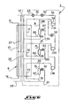
- the open circuit of gas for example natural gas, to be liquefied
- the closed circuit of main refrigerant fluid is designated in a manner general by the reference numeral 2
- the closed auxiliary refrigerant circuit is designated by the reference numeral 3.
- the closed main and auxiliary refrigerant circuits are symbolically delimited and contained within a rectangular frame drawn in line discontinuous in broken lines, and the path of the gas to be liquefied is indicated by a continuous line in thick solid line.
- the liquefied gas circuit 1 and the main refrigerant circuit 2 are thermally combined or interconnected by means of common cryogenic heat exchangers respectively for liquefaction and gas sub-cooling 4, on the one hand, and preliminary gas cooling 5, on the other hand.
- the main 2 and auxiliary 3 refrigerant circuits respectively are combined by means of at least one common cryogenic heat exchanger 6 for precooling and at least partial liquefaction of the main refrigerant.
- the open circuit 1 of gas to be liquefied comprises a line 7 arriving at the pre-cooling heat exchanger 5 connected to at least one internal flow path 8 of this exchanger, the nettle of which is connected by a line 9 to an optional gas treatment apparatus 10, in particular for the extraction of ethane.
- gas treatment apparatus 10 in particular for the extraction of ethane.
- a nitrogen extraction device can for example be provided at the level of the cryogenic heat exchanger 4.
- the outlet of this device 10 is connected by a line 11 at the inlet of the heat exchanger 4.
- a bypass 12 of the pipe 7 can optionally be provided, a bypass 12 which is connected to a flow path 13 of part of the gas to be liquefied in the cryogenic heat exchanger 6 of the auxiliary refrigerant circuit, the outlet of which is connected by a flow path 14 to the pipe 11 before the entry of the heat exchanger 4.
- the pipe 11 is connected to an internal flow path 15 passing through the cryogenic heat exchanger 4 and the downstream end is connected, at the outlet of the heat exchanger 4 to a pipe 16 of liquefied natural gas through at least one expansion member 17 such as for example an expansion valve.
- the closed circuit 2 contains a main refrigerant consisting of a mixture of several components, at least the major part of which is advantageously formed of hydrocarbons.
- the relative composition in moles of this refrigerant fluid can be for example the following:
- This circuit 2 successively comprises in the direction of flow of the coolant: a first compressor 18 and a second compressor 19 of coolant in the gaseous state, each driven either separately by an individual drive machine or else jointly by a drive machine common then having their respective shafts mechanically coupled.
- These two compressors 18, 19 are connected in series to an exchanger-cooler 20, the coolant of which is advantageously of external origin and constituted for example by water or air.
- the compressors 21, 22 can be driven jointly or alternatively jointly with at least one of the compressors 18, 19, or separately each.
- the outlet of the exchanger-cooler 20 is connected by a line 21 to a third compressor 22 and a fourth compressor 23 connected in series through at least one intermediate cooler 24, the coolant of which is advantageously of external origin and constituted by for example by water or air.
- the outlet and discharge port of the compressor 23 is connected by a line 25, through an exchanger-cooler 26 (the coolant of which is advantageously of external origin, such as for example water or air ), at the inlet of the heat exchanger 6 and more precisely at the upstream end of at least one internal flow path 27 extending therein.
- the cryogenic heat exchanger 6 of the auxiliary refrigerant circuit is advantageously a plate exchanger.
- the downstream end of the flow path 27 is connected by a pipe 28 to at least one separator of phases 29.
- the liquid collecting space of this phase separator is connected by a pipe 30 to the inlet of the heat exchanger 4 and more precisely to the upstream end of at least one flow path 31 extending inside the heat exchanger 4 in substantially the same direction as the internal flow path 15 of the gas to be liquefied.
- the downstream end of the internal flow path 31 is divided, after the exit from the heat exchanger 4, into two flow paths 33, 32 respectively, connected to the inlet of expansion members 34, 35 respectively.
- At the outlet of each expansion member 34, 35 is connected a flow path 36, 37 extending inside the cryogenic heat exchanger 4 in substantially the same direction as the internal flow path 15 of the gas to liquefy and to flow path 31, and against the current.
- the vapor collector space of the phase separator 29 is connected by a pipe 38 to the inlet of the cryogenic heat exchanger 4 and more precisely to the upstream end of at least one other internal flow path 39 s extending substantially parallel to the flow paths 15 and 31.
- the downstream end of this flow path 39 is divided, after the exit from the heat exchanger 4, into two flow paths 40, 41 connected to the inlet of expansion members 42, 43, respectively, the outlet of expansion members 42, 43 is connected to flow paths 44, 45, respectively, extending inside the cryogenic heat exchanger 4 in substantially the same direction as the other flow paths 15, 31, 36, 37 and 39.
- the cryogenic heat exchanger 4 of the main refrigerant circuit 2 is a plate heat exchanger comprising, as seen above, different passageways for each of the fluids present during the heat exchange, namely the gas to be liquefied, the liquid or vapor phases or fractions of the partially condensed main refrigerant, as well as the fractions from the previous ones, expanded at different pressure levels.
- the flow paths 36 and 44 of the fractions of the main coolant expanded at the same pressure for example an average pressure, in particular between approximately 1.5 and 3 bars, meet in one single flow path 46 which can optionally pass through the heat exchanger 5 for precooling the gas to be liquefied, in particular against the current, the downstream end of this flow path 46 being connected to the suction port of the compressor 19.
- the flow paths 37 and 45 of the fractions of the main coolant expanded at the same pressure in particular a low pressure, for example less than about 1 effective bar meet in a single flow path 47 whose downstream end opens into the suction port of the compressor 18.
- Circuit 3 contains an auxiliary refrigerant consisting of a mixture preferably only based on hydrocarbons, for example having the following relative molar composition:
- the closed circuit 3 of the auxiliary refrigerant fluid successively comprises the following elements in the direction of flow of the fluid: first 48, second 49 and third 51 compressors connected in series with each other and driven either by individual motor machines or else by at least one drive machine common to at least two compressors which are then directly mechanically coupled by their respective shafts.
- the outlet or discharge port of the second compressor 49 is connected to the inlet or suction port of the third compressor 51 by a pipe 54 through a heat exchanger-cooler 50 with cooling agent preferably of external origin such as such as water or air.
- the outlet or discharge port of the third compressor 51 is connected by a line 55 to a condenser 52, the outlet of which is connected by a line 56 to a sub-cooler 53.
- the outlet of the sub-cooler 53 is connected by a pipe 57 to the cryogenic heat exchanger 6, which may in particular be constituted by a plate exchanger, and more particularly to the upstream end of a flow path 58 passing through the heat exchanger 6 in a direction substantially parallel to the flow paths 13 and 27 of the gas to be liquefied and the main refrigerant, respectively.
- the cryogenic heat exchanger 6 which may in particular be constituted by a plate exchanger, and more particularly to the upstream end of a flow path 58 passing through the heat exchanger 6 in a direction substantially parallel to the flow paths 13 and 27 of the gas to be liquefied and the main refrigerant, respectively.
- the flow path 58 of the auxiliary refrigerant in the cryogenic heat exchanger 6 has, for example, three branches 59, 6Q and 61 provided at three different levels in the exchanger 6.
- the three branches 59, 60 and 61 are each connected to an expansion member 62, 63 and 64, respectively, the outlet of which is connected to a vapor and liquid phase separator 65, 66 and 67, respectively.
- the liquid collecting space of the phase separators 65, 66 and 67 is connected by a line 68, 69 and 70, respectively, to an inlet of the cryogenic heat exchanger 6 and more precisely to the upstream end of a flow path 71, 72 and 73, respectively, the major part of which extends inside the cryogenic heat exchanger 6 in a direction at least approximately parallel to the flow paths 13 of the gas to be liquefied, 27 of the main refrigerant and 58 of the auxiliary refrigerant before expansion.
- each phase separator 65, 66, 67 are connected by a pipe 74, 75 and 76, respectively, to an inlet of the cryogenic heat exchanger 6 and more particularly at the upstream end a flow path 77, 78, 79 the major part of which extends inside the cryogenic heat exchanger 6 in substantially the same direction as the other internal flow paths 13, 27 and 58.
- the flow path 82 is connected to the suction port of the compressor 48, the flow path 81 is connected to the suction port of the compressor 49 and the flow path 80 is connected to the port compressor 51.
- Circuit 1 operates as follows: the gas to be liquefied, for example natural gas, arriving via line 7 at a temperature, for example, of approximately + 20 ° C. and at a pressure, for example, of approximately 42.5 bars, crosses the passageway 8 of the heat exchanger 5 to be cooled there preliminary by heat exchange with the main refrigerant vaporized after expansion in the cryogenic heat exchanger 4 and circulating in the flow path 46 in the opposite direction to direction of flow of the gas in the passageway 8. Leaving the heat exchanger 5 via line 9, the gas is then at a temperature for example of approximately -45 ° C. and at a pressure for example of around 42 bars.
- the treatment apparatus 10 passes through the treatment apparatus 10 to reach via the pipe 11 the entry of the flow path 15 into the plate exchanger 4 to be entirely liquefied there and then sub-cooled by heat exchange with the main refrigerant. .
- the liquefied gas is at a temperature, for example, of approximately -154 ° C. and at a pressure, for example, of approximately 41.5 bars. It is then expanded in the expansion valve 17 and then transferred to the place of conservation or storage of liquefied natural gas or to a place of treatment or use thereof.
- Part of the gas to be liquefied can also be previously cooled by heat exchange with the auxiliary refrigerant in the cryogenic heat exchanger 6, this part then being combined with the rest of the gas to be liquefied before it enters the cryogenic heat exchanger 4 .
- Cycle 2 of the main refrigerant operates in the following manner: the part of the main refrigerant expanded at low pressure is sucked in the gaseous state, at a temperature for example of approximately -52 ° C. and at a pressure for example d '' about 0.08 bar by the first compressor 18 from which it is discharged at an average pressure of approximately for example 2 bars and at a temperature of approximately for example 10 ° C., then it is sucked in by the second compressor 19, at the same time as the part of the main coolant relaxed at an average pressure equal for example to about 2 bars and whose temperature is for example about 10 ° C.
- the assembly is discharged from the compressor 19 at a temperature equal for example to approximately 71 ° C.
- the exchanger-cooler 20 in which the temperature of the main refrigerant is lowered at about, for example, 15 ° C. Via the flow path 21, it then enters the suction port of the compressor 22, passes through the exchanger-cooler 24 then is compressed in the compressor 23 and, via the flow path 25, passes through the exchanger of heat 26.
- the main refrigerant is for example at a temperature of approximately 15 ° C. and at a pressure of approximately 27.4 bars. It then enters the flow path 27 of the cryogenic heat exchanger 6 where the main cooling fluid is cooled by heat exchange with the auxiliary cooling fluid so as to at least partially liquefy.
- the main refrigerant thus at least partially condensed at a temperature for example of around -50 ° C. and at a pressure for example of around 26.5 bars, then leaves the heat exchanger 6 in the form of a mixture of gaseous and liquid phases respectively which are then separated in the phase separator 29.
- the gaseous phase is brought by line 38 into the segment of the flow path 39 located in the cryogenic heat exchanger 4 to be there liquefied and then sub-cooled to a temperature for example of around -154 ° C.
- Part of this liquefied and sub-cooled gaseous phase flows in the channel 41 and is expanded in the expansion member 43 to a pressure for example of approximately 0.3 bar, its temperature being for example of approximately - 156 ° C.
- the temperature and pressure conditions are for example around -52 ° C and around 0.08 bar, respectively .
- the other part of the liquefied and sub-cooled gaseous phase flows through the channel 40 and is expanded in the expansion member 42 to a pressure for example of about 2.3 bars, its temperature being about -153 ° C.
- the temperature and pressure conditions are, for example, as follows: -152 ° C and 2.10 bars.
- the liquid phase of the main refrigerant coming from the phase separator 29 is brought via line 30 into the flow path 31 of the cryogenic heat exchanger 4 to be sub-cooled there to a temperature by example of approximately -154 ° C, at a pressure for example of approximately 26 bars.
- Part of the sub-cooled liquid phase of the main cooling fluid passes through the expansion member 35 where its pressure is reduced to, for example, approximately 0.3 bar; while another part of the sub-cooled liquid phase flowing in the channel 33 is expanded in the expansion member 34 at a pressure of about 2.3 bars, its temperature being about for example -153 ° C.
- the first and second aforementioned parts of the liquid phase of the refrigerant main have the following temperature and pressure conditions: -52 ° C and 0.08 bar, and -52 ° C and 2.10 bar, respectively.
- a first part of the vapor phase of the main refrigerant, condensed and sub-cooled is expanded at a first pressure, a second part being expanded at a second pressure, and a first part of the aforementioned liquid phase.
- main, sub-cooled refrigerant is expanded at said first pressure, a second portion being expanded at said second pressure.
- the vapor and liquid phases can be divided into a desired number of parts, for example three or more, the pressure at which a part of the liquid phase being expanded corresponds to the pressure at which a corresponding portion of the vapor phase.
- the first parts of the vapor and liquid phases are mixed, and the second parts of said vapor and liquid phases are mixed.
- Another possibility consists in mixing the first parts of the vapor and liquid phases, and in mixing the second parts of the vapor and liquid phases after expansion but before vaporization (embodiment illustrated in FIG. 5).
- the part of the main refrigerant vaporized at low pressure is admitted by the flow path 47 into the suction port of the compressor 18, while the part of the main refrigerant vaporized at medium pressure is admitted by the path d 'flow 46, and possibly after having passed through the heat exchanger 5 for precooling the gas to be liquefied, in the suction orifice of the compressor 19.
- the auxiliary refrigerant cycle 3 is as follows: the auxiliary refrigerant, in the gaseous state, leaving the compressor group 48, 49, 51 is for example at a temperature of approximately + 46 ° C and at a pressure for example around 16 bars. After passing through the cooler exchangers 52 and 53, the temperature of the auxiliary refrigerant is approximately + 13 ° C., while its pressure is approximately 15.1 bars. The part of the auxiliary refrigerating fluid diverted in the flow path 59 is at a temperature for example of approximately 0 ° C. and at a pressure for example of approximately 15 bars. After expansion in the expansion member 62, the temperature drops to, for example, approximately -6.5 ° C and the pressure to, for example, approximately 8.5 bars.
- the temperature and pressure conditions of the second part of the auxiliary refrigerant flowing through the bypass 60 are as follows: for example about -25 ° C and for example about 14.5 bars. After expansion in the expansion member 63, the temperature is lowered to, for example, approximately -29 ° C and the pressure to, for example, approximately 4 bars.
- the vapor and liquid phases thus obtained flow in the flow paths 78 and 72, respectively, in the exchanger 6 so as to participate in the heat exchange with the other fluids flowing in said exchanger 6, then are gathered after the exit of said exchanger 6 in the flow path 81.
- the temperature and pressure conditions of this part of the auxiliary refrigerant are then as follows: for example around -3 ° C. and for example around 3.9 bars. This part of the auxiliary refrigerant is introduced into the suction port of the compressor 49.
- a third part of the auxiliary cooling fluid flows in the flow path 61 at a temperature for example of around -50 ° C. and a pressure for example of around 14.2 bars.
- these temperature and pressure conditions change as follows: for example approximately -54 ° C. and for example approximately 1.1 bars.
- the vapor and liquid phases thus obtained are separated in the phase separator 67 and then flow through the flow paths 73 and 79 in the heat exchanger 6 to participate in the heat exchange with the other fluids which circulate there.
- These vapor and liquid phases, once united, after leaving the exchanger 6, are at a temperature for example of around -28 ° C. and at a pressure for example of around 0.90 bar.
- This third part of the auxiliary refrigerant is introduced into the suction port of the compressor 48 by the flow path 82.
- FIG. 2 representing an alternative embodiment of the apparatus according to the invention, only a part of it has been shown framed in dashed lines in FIG. 1; the rest of the device. being identical.
- the vapor phase of the main condensing fluid condensed and sub-cooled in the exchanger 4 is expanded, in one go, by the expansion member 83 at a first pressure.
- the liquid phase of the main refrigerant sub-cooled in the exchanger 4 is expanded, at once, to a second pressure different from said first pressure, in the expansion member 84.
- the vapor phase, expanded for example to a low pressure, less than about 1 effective bar, is conducted, through the heat exchanger 4, through the flow path 85, to the suction port of the first condenser 18; while the liquid phase of the main refrigerant, expanded to an average pressure, in particular between approximately 1.5 and approximately 3 bars, is conveyed, through the exchanger 4, by the flow path 86 to the orifice suction of the second compressor 19.
- the general operation of the apparatus for cooling and liquefying a gas with low boiling point, such as for example natural gas, comprising the variant of the figure 2 is similar to that of the apparatus according to FIG. 1.
- FIG. 3 representing another variant of the same part (indicated by a dashed line frame in FIG. 1), of the apparatus as in FIG. 2.
- the gaseous and liquid phases thus obtained are separated in a phase separator 87 before crossing again, against -current, the cryogenic heat exchanger 4.
- the two phases are combined in the same flow path 89 connected to the suction port of the compressor 18, the vapor phase is therefore, in this case, relaxed at the aforementioned low pressure.
- the sub-cooled liquid phase of the main cooling fluid is expanded in the expansion member 84, and flows against the current in the exchanger 4 at the outlet of which is connected the flow path 90 itself connected to the compressor suction port 19.
- the vapor phase coming from the separator 87 may not pass back into the exchanger 4 but be introduced directly into the pipe 89.
- FIG. 6 illustrates the application of this variant to the auxiliary refrigeration circuit.
- the pipes 74, 75, 76 coming from the vapor collecting space of the separators 65, 66, 67 are connected directly to the flow paths 80, 81, 82 without passing through the exchanger 6.
- Figure 4 is a view of an alternative embodiment of the part of the apparatus framed in broken lines in Figure 1, similar to the variant illustrated in Figure 2.
- the location of each element of the system expansion 83, 84 relative to the cryogenic heat exchanger 4 of the main refrigerant circuit 2, instead of being at the outlet of the exchanger 4, may be provided, at any location, along the exchanger 4, in the direction of flow of the various fluids.
- the flow path 31 of the liquid phase of the main cooling fluid does not cross the entire exchanger 4. This makes it possible to achieve expansion at different temperature levels, in the case, after the valve, the temperature could be higher.
- the displacement of the expansion according to a temperature gradient corresponds to a displacement of the expansion member along the exchanger, in the direction of flow of the fluids.
- FIG. 5 illustrates an alternative embodiment in which the first parts of the vapor and liquid phases are mixed and the second parts of said vapor and liquid phases are mixed, after expansion, in the valves 83, 84 '; 83 ', 84, respectively, but before recirculation against the current, in the exchanger 4.
- Molar composition molar percentage vaporized in the phase separator 29: 20%.
Landscapes
- Engineering & Computer Science (AREA)
- Physics & Mathematics (AREA)
- Mechanical Engineering (AREA)
- Thermal Sciences (AREA)
- General Engineering & Computer Science (AREA)
- Chemical & Material Sciences (AREA)
- Chemical Kinetics & Catalysis (AREA)
- General Chemical & Material Sciences (AREA)
- Oil, Petroleum & Natural Gas (AREA)
- Separation By Low-Temperature Treatments (AREA)
Applications Claiming Priority (2)
| Application Number | Priority Date | Filing Date | Title |
|---|---|---|---|
| FR8307620 | 1983-05-06 | ||
| FR8307620A FR2545589B1 (fr) | 1983-05-06 | 1983-05-06 | Procede et appareil de refroidissement et liquefaction d'au moins un gaz a bas point d'ebullition, tel que par exemple du gaz naturel |
Publications (3)
| Publication Number | Publication Date |
|---|---|
| EP0125980A2 true EP0125980A2 (de) | 1984-11-21 |
| EP0125980A3 EP0125980A3 (en) | 1984-12-27 |
| EP0125980B1 EP0125980B1 (de) | 1987-04-01 |
Family
ID=9288670
Family Applications (1)
| Application Number | Title | Priority Date | Filing Date |
|---|---|---|---|
| EP84400906A Expired EP0125980B1 (de) | 1983-05-06 | 1984-05-03 | Kühl- und Verflüssigungsverfahren und Anlage für mindestens ein Gas mit niedrigem Siedepunkt, wie z.B. Erdgas |
Country Status (13)
| Country | Link |
|---|---|
| US (1) | US4539028A (de) |
| EP (1) | EP0125980B1 (de) |
| JP (1) | JPH0627618B2 (de) |
| AU (1) | AU560904B2 (de) |
| CA (1) | CA1226206A (de) |
| DE (1) | DE3462945D1 (de) |
| ES (1) | ES8502536A1 (de) |
| FR (1) | FR2545589B1 (de) |
| IN (1) | IN161272B (de) |
| MY (1) | MY101481A (de) |
| NO (1) | NO159683C (de) |
| OA (1) | OA07764A (de) |
| SU (1) | SU1627097A3 (de) |
Families Citing this family (38)
| Publication number | Priority date | Publication date | Assignee | Title |
|---|---|---|---|---|
| GB2180921B (en) * | 1985-09-25 | 1990-01-24 | Sanyo Electric Co | Refrigeration system |
| US4911741A (en) * | 1988-09-23 | 1990-03-27 | Davis Robert N | Natural gas liquefaction process using low level high level and absorption refrigeration cycles |
| FR2681859B1 (fr) * | 1991-09-30 | 1994-02-11 | Technip Cie Fse Etudes Const | Procede de liquefaction de gaz naturel. |
| US5271231A (en) * | 1992-08-10 | 1993-12-21 | L'air Liquide, Societe Anonyme Pour L'etude Et L'exploitation Des Procedes Georges Claude | Method and apparatus for gas liquefaction with plural work expansion of feed as refrigerant and air separation cycle embodying the same |
| US5615561A (en) * | 1994-11-08 | 1997-04-01 | Williams Field Services Company | LNG production in cryogenic natural gas processing plants |
| FR2743140B1 (fr) * | 1995-12-28 | 1998-01-23 | Inst Francais Du Petrole | Procede et dispositif de liquefaction en deux etapes d'un melange gazeux tel qu'un gaz naturel |
| US5657643A (en) * | 1996-02-28 | 1997-08-19 | The Pritchard Corporation | Closed loop single mixed refrigerant process |
| US5746066A (en) * | 1996-09-17 | 1998-05-05 | Manley; David B. | Pre-fractionation of cracked gas or olefins fractionation by one or two mixed refrigerant loops and cooling water |
| US6659730B2 (en) * | 1997-11-07 | 2003-12-09 | Westport Research Inc. | High pressure pump system for supplying a cryogenic fluid from a storage tank |
| US6446465B1 (en) * | 1997-12-11 | 2002-09-10 | Bhp Petroleum Pty, Ltd. | Liquefaction process and apparatus |
| US6119479A (en) | 1998-12-09 | 2000-09-19 | Air Products And Chemicals, Inc. | Dual mixed refrigerant cycle for gas liquefaction |
| MY117548A (en) | 1998-12-18 | 2004-07-31 | Exxon Production Research Co | Dual multi-component refrigeration cycles for liquefaction of natural gas |
| US6471694B1 (en) | 2000-08-09 | 2002-10-29 | Cryogen, Inc. | Control system for cryosurgery |
| US7004936B2 (en) | 2000-08-09 | 2006-02-28 | Cryocor, Inc. | Refrigeration source for a cryoablation catheter |
| US6347532B1 (en) | 1999-10-12 | 2002-02-19 | Air Products And Chemicals, Inc. | Gas liquefaction process with partial condensation of mixed refrigerant at intermediate temperatures |
| MY125082A (en) * | 1999-12-15 | 2006-07-31 | Shell Int Research | Compression apparatus for gaseous refrigerant |
| FR2821351B1 (fr) * | 2001-02-26 | 2003-05-16 | Technip Cie | Procede de recuperation d'ethane, mettant en oeuvre un cycle de refrigeration utilisant un melange d'au moins deux fluides refrigerants, gaz obtenus par ce procede, et installation de mise en oeuvre |
| US6647744B2 (en) * | 2002-01-30 | 2003-11-18 | Exxonmobil Upstream Research Company | Processes and systems for liquefying natural gas |
| US6640586B1 (en) * | 2002-11-01 | 2003-11-04 | Conocophillips Company | Motor driven compressor system for natural gas liquefaction |
| WO2005028975A2 (en) * | 2003-09-23 | 2005-03-31 | Statoil Asa | Natural gas liquefaction process |
| DE102004011481A1 (de) * | 2004-03-09 | 2005-09-29 | Linde Ag | Verfahren zum Verflüssigen eines Kohlenwasserstoff-reichen Stromes |
| US8491636B2 (en) | 2004-03-23 | 2013-07-23 | Medtronic Cryopath LP | Method and apparatus for inflating and deflating balloon catheters |
| US7727228B2 (en) | 2004-03-23 | 2010-06-01 | Medtronic Cryocath Lp | Method and apparatus for inflating and deflating balloon catheters |
| CN100344872C (zh) * | 2004-06-11 | 2007-10-24 | 中国科学院理化技术研究所 | 高真空深冷水汽捕集器 |
| CA2567052C (en) * | 2004-06-23 | 2013-09-24 | Exxonmobil Upstream Research Company | Mixed refrigerant liquefaction process |
| US8206345B2 (en) | 2005-03-07 | 2012-06-26 | Medtronic Cryocath Lp | Fluid control system for a medical device |
| JP2010507771A (ja) * | 2006-10-23 | 2010-03-11 | シエル・インターナシヨネイル・リサーチ・マーチヤツピイ・ベー・ウイ | 炭化水素流を液化する方法及び装置 |
| EP2082178B1 (de) * | 2006-11-14 | 2018-08-29 | Shell International Research Maatschappij B.V. | Verfahren und vorrichtung zur kühlung eines kohlenwasserstoffreichen stromes |
| DE102007006370A1 (de) * | 2007-02-08 | 2008-08-14 | Linde Ag | Verfahren zum Verflüssigen eines Kohlenwasserstoff-reichen Stromes |
| AU2009316236B2 (en) * | 2008-11-17 | 2013-05-02 | Woodside Energy Limited | Power matched mixed refrigerant compression circuit |
| FR2957407B1 (fr) * | 2010-03-15 | 2012-08-17 | Inst Francais Du Petrole | Procede de liquefaction d'un gaz naturel avec des melanges refrigerants contenant au moins un hydrocarbure insature |
| WO2011117655A2 (en) | 2010-03-25 | 2011-09-29 | The University Of Manchester | Refrigeration process |
| CN104011487B (zh) * | 2011-12-20 | 2017-03-01 | 科诺科菲利浦公司 | 运动环境中冷却或液化工艺气体的系统和方法 |
| CN103322769B (zh) * | 2012-03-20 | 2015-07-08 | 中国海洋石油总公司 | 一种基荷型天然气液化工厂的级联式液化系统 |
| DE102013016695A1 (de) * | 2013-10-08 | 2015-04-09 | Linde Aktiengesellschaft | Verfahren zum Verflüssigen einer Kohlenwasserstoff-reichen Fraktion |
| WO2016094168A1 (en) * | 2014-12-12 | 2016-06-16 | Dresser-Rand Company | System and method for liquefaction of natural gas |
| RU2601670C1 (ru) * | 2015-07-22 | 2016-11-10 | Федеральное Государственное Автономное Образовательное Учреждение Высшего Профессионального Образования "Дальневосточный Федеральный Университет" (Двфу) | Холодильная машина |
| US11248840B2 (en) * | 2017-12-15 | 2022-02-15 | Saudi Arabian Oil Company | Process integration for natural gas liquid recovery |
Family Cites Families (4)
| Publication number | Priority date | Publication date | Assignee | Title |
|---|---|---|---|---|
| FR2292203A1 (fr) * | 1974-11-21 | 1976-06-18 | Technip Cie | Procede et installation pour la liquefaction d'un gaz a bas point d'ebullition |
| FR2471566B1 (fr) * | 1979-12-12 | 1986-09-05 | Technip Cie | Procede et systeme de liquefaction d'un gaz a bas point d'ebullition |
| FR2499226B1 (fr) * | 1981-02-05 | 1985-09-27 | Air Liquide | Procede et installation de liquefaction d'un gaz |
| US8929456B2 (en) | 2010-09-30 | 2015-01-06 | Alcatel Lucent | Video coding using compressive measurements |
-
1983
- 1983-05-06 FR FR8307620A patent/FR2545589B1/fr not_active Expired
-
1984
- 1984-04-24 IN IN347/DEL/84A patent/IN161272B/en unknown
- 1984-04-26 US US06/604,049 patent/US4539028A/en not_active Expired - Lifetime
- 1984-04-27 AU AU27460/84A patent/AU560904B2/en not_active Ceased
- 1984-05-02 CA CA000453353A patent/CA1226206A/en not_active Expired
- 1984-05-03 DE DE8484400906T patent/DE3462945D1/de not_active Expired
- 1984-05-03 EP EP84400906A patent/EP0125980B1/de not_active Expired
- 1984-05-04 SU SU843737939A patent/SU1627097A3/ru active
- 1984-05-04 OA OA58289A patent/OA07764A/xx unknown
- 1984-05-04 ES ES532222A patent/ES8502536A1/es not_active Expired
- 1984-05-04 NO NO841803A patent/NO159683C/no not_active IP Right Cessation
- 1984-05-07 JP JP59090837A patent/JPH0627618B2/ja not_active Expired - Fee Related
-
1987
- 1987-09-30 MY MYPI87002502A patent/MY101481A/en unknown
Also Published As
| Publication number | Publication date |
|---|---|
| EP0125980B1 (de) | 1987-04-01 |
| NO841803L (no) | 1984-11-07 |
| JPH0627618B2 (ja) | 1994-04-13 |
| FR2545589A1 (fr) | 1984-11-09 |
| ES532222A0 (es) | 1985-01-01 |
| NO159683B (no) | 1988-10-17 |
| SU1627097A3 (ru) | 1991-02-07 |
| DE3462945D1 (en) | 1987-05-07 |
| AU560904B2 (en) | 1987-04-16 |
| FR2545589B1 (fr) | 1985-08-30 |
| NO159683C (no) | 1989-01-25 |
| AU2746084A (en) | 1984-11-08 |
| ES8502536A1 (es) | 1985-01-01 |
| IN161272B (de) | 1987-11-07 |
| US4539028A (en) | 1985-09-03 |
| EP0125980A3 (en) | 1984-12-27 |
| OA07764A (fr) | 1985-08-30 |
| JPS6099982A (ja) | 1985-06-03 |
| CA1226206A (en) | 1987-09-01 |
| MY101481A (en) | 1991-11-18 |
Similar Documents
| Publication | Publication Date | Title |
|---|---|---|
| EP0125980B1 (de) | Kühl- und Verflüssigungsverfahren und Anlage für mindestens ein Gas mit niedrigem Siedepunkt, wie z.B. Erdgas | |
| RU2395764C2 (ru) | Установка и способ для сжижения природного газа | |
| CN108955084B (zh) | 混合制冷剂系统和方法 | |
| FR2471566A1 (fr) | Procede et systeme de liquefaction d'un gaz a bas point d'ebullition | |
| CA2269147C (fr) | Procede et dispositif de liquefaction d'un gaz naturel sans separation de phases sur les melanges refrigerants | |
| RU2304746C2 (ru) | Способ и установка для сжижения природного газа | |
| EP0818661B1 (de) | Verbessertes Verfahren und Anlage für die Kühlung und Verflüssigung von Erdgas | |
| CA1054922A (fr) | Procede et installation pour la liquefaction d'un gaz a bas point d'ebullition | |
| US6658890B1 (en) | Enhanced methane flash system for natural gas liquefaction | |
| CA2342822C (en) | Conversion of normally gaseous material to liquefied product | |
| FR2471567A1 (fr) | Procede et systeme de refrigeration d'un fluide a refroidir a basse temperature | |
| FR2611386A1 (fr) | Procede perfectionne pour liquefier un flux d'alimentation en gaz naturel, en utilisant un ou deux refrigerants en circuit ferme a plusieurs composants | |
| AU2003214921A1 (en) | Processes and systems for liquefying natural gas | |
| EP3830511B1 (de) | Verfahren zum austausch von wärme | |
| EP2417411B1 (de) | Kühlverfahren und system zur kälterückgewinnung aus methan durch kältemittel | |
| WO2009153427A2 (fr) | Procede de liquefaction d'un gaz naturel avec pre-refroidissement du melange refrigerant | |
| FR3149079A1 (fr) | Installation et procédé de liquéfaction d’hydrogène | |
| CH693187A5 (fr) | Procédé et installation de production frigorifique à partir d'un cycle thermique d'un fluide à bas point d'ébullition. | |
| EP4348138A1 (de) | Verfahren und anlage zur wasserstoffverflüssigung | |
| WO2011114012A2 (fr) | Procédé de liquefaction d'un gaz naturel avec des melanges refrigerants contenant au moins un hydrocarbure insature | |
| RU2803441C1 (ru) | Способ сжижения природного газа на одиночном смешанном хладагенте "Энергия Восхода" и установка для его осуществления | |
| WO2005103583A1 (fr) | Procede de liquefaction d’un gaz integrant un appareillage de refroidissement thermo-acoustique | |
| FR2858830A1 (fr) | Procede pour augmenter la capacite et l'efficacite d'installations gazieres du type comprenant une turbine a gaz | |
| WO2022253847A1 (fr) | Dispositif et procede de pre-refroidissement d'un flux d'un fluide cible a une temperature inferieure ou egale a 90 k | |
| WO2025008315A1 (fr) | Installation et procédé de production d'un fluide cryogénique |
Legal Events
| Date | Code | Title | Description |
|---|---|---|---|
| PUAI | Public reference made under article 153(3) epc to a published international application that has entered the european phase |
Free format text: ORIGINAL CODE: 0009012 |
|
| PUAL | Search report despatched |
Free format text: ORIGINAL CODE: 0009013 |
|
| AK | Designated contracting states |
Designated state(s): BE DE GB IT NL |
|
| AK | Designated contracting states |
Designated state(s): BE DE GB IT NL |
|
| 17P | Request for examination filed |
Effective date: 19850204 |
|
| GRAA | (expected) grant |
Free format text: ORIGINAL CODE: 0009210 |
|
| AK | Designated contracting states |
Kind code of ref document: B1 Designated state(s): BE DE GB IT NL |
|
| REF | Corresponds to: |
Ref document number: 3462945 Country of ref document: DE Date of ref document: 19870507 |
|
| ITF | It: translation for a ep patent filed | ||
| PLBE | No opposition filed within time limit |
Free format text: ORIGINAL CODE: 0009261 |
|
| STAA | Information on the status of an ep patent application or granted ep patent |
Free format text: STATUS: NO OPPOSITION FILED WITHIN TIME LIMIT |
|
| 26N | No opposition filed | ||
| ITTA | It: last paid annual fee | ||
| REG | Reference to a national code |
Ref country code: GB Ref legal event code: IF02 |
|
| PGFP | Annual fee paid to national office [announced via postgrant information from national office to epo] |
Ref country code: GB Payment date: 20030529 Year of fee payment: 20 |
|
| PGFP | Annual fee paid to national office [announced via postgrant information from national office to epo] |
Ref country code: NL Payment date: 20030530 Year of fee payment: 20 |
|
| PGFP | Annual fee paid to national office [announced via postgrant information from national office to epo] |
Ref country code: DE Payment date: 20030602 Year of fee payment: 20 |
|
| PGFP | Annual fee paid to national office [announced via postgrant information from national office to epo] |
Ref country code: BE Payment date: 20030611 Year of fee payment: 20 |
|
| PG25 | Lapsed in a contracting state [announced via postgrant information from national office to epo] |
Ref country code: GB Free format text: LAPSE BECAUSE OF EXPIRATION OF PROTECTION Effective date: 20040502 |
|
| PG25 | Lapsed in a contracting state [announced via postgrant information from national office to epo] |
Ref country code: NL Free format text: LAPSE BECAUSE OF EXPIRATION OF PROTECTION Effective date: 20040503 |
|
| REG | Reference to a national code |
Ref country code: GB Ref legal event code: PE20 |
|
| BE20 | Be: patent expired |
Owner name: *CIE FRANCAISE D'ETUDES ET DE CONSTRUCTION TECHNIP Effective date: 20040503 |
|
| NLV7 | Nl: ceased due to reaching the maximum lifetime of a patent |
Effective date: 20040503 |