EP0125985A2 - Sonnenheizsystem - Google Patents
Sonnenheizsystem Download PDFInfo
- Publication number
- EP0125985A2 EP0125985A2 EP84400923A EP84400923A EP0125985A2 EP 0125985 A2 EP0125985 A2 EP 0125985A2 EP 84400923 A EP84400923 A EP 84400923A EP 84400923 A EP84400923 A EP 84400923A EP 0125985 A2 EP0125985 A2 EP 0125985A2
- Authority
- EP
- European Patent Office
- Prior art keywords
- liquid
- exchanger
- separator
- heat
- pump
- Prior art date
- Legal status (The legal status is an assumption and is not a legal conclusion. Google has not performed a legal analysis and makes no representation as to the accuracy of the status listed.)
- Withdrawn
Links
Images
Classifications
-
- F—MECHANICAL ENGINEERING; LIGHTING; HEATING; WEAPONS; BLASTING
- F28—HEAT EXCHANGE IN GENERAL
- F28D—HEAT-EXCHANGE APPARATUS, NOT PROVIDED FOR IN ANOTHER SUBCLASS, IN WHICH THE HEAT-EXCHANGE MEDIA DO NOT COME INTO DIRECT CONTACT
- F28D15/00—Heat-exchange apparatus with the intermediate heat-transfer medium in closed tubes passing into or through the conduit walls ; Heat-exchange apparatus employing intermediate heat-transfer medium or bodies
- F28D15/02—Heat-exchange apparatus with the intermediate heat-transfer medium in closed tubes passing into or through the conduit walls ; Heat-exchange apparatus employing intermediate heat-transfer medium or bodies in which the medium condenses and evaporates, e.g. heat pipes
- F28D15/0266—Heat-exchange apparatus with the intermediate heat-transfer medium in closed tubes passing into or through the conduit walls ; Heat-exchange apparatus employing intermediate heat-transfer medium or bodies in which the medium condenses and evaporates, e.g. heat pipes with separate evaporating and condensing chambers connected by at least one conduit; Loop-type heat pipes; with multiple or common evaporating or condensing chambers
-
- F—MECHANICAL ENGINEERING; LIGHTING; HEATING; WEAPONS; BLASTING
- F24—HEATING; RANGES; VENTILATING
- F24D—DOMESTIC- OR SPACE-HEATING SYSTEMS, e.g. CENTRAL HEATING SYSTEMS; DOMESTIC HOT-WATER SUPPLY SYSTEMS; ELEMENTS OR COMPONENTS THEREFOR
- F24D11/00—Central heating systems using heat accumulated in storage masses
- F24D11/002—Central heating systems using heat accumulated in storage masses water heating system
- F24D11/003—Central heating systems using heat accumulated in storage masses water heating system combined with solar energy
-
- F—MECHANICAL ENGINEERING; LIGHTING; HEATING; WEAPONS; BLASTING
- F24—HEATING; RANGES; VENTILATING
- F24H—FLUID HEATERS, e.g. WATER OR AIR HEATERS, HAVING HEAT-GENERATING MEANS, e.g. HEAT PUMPS, IN GENERAL
- F24H1/00—Water heaters, e.g. boilers, continuous-flow heaters or water-storage heaters
- F24H1/18—Water-storage heaters
-
- F—MECHANICAL ENGINEERING; LIGHTING; HEATING; WEAPONS; BLASTING
- F24—HEATING; RANGES; VENTILATING
- F24H—FLUID HEATERS, e.g. WATER OR AIR HEATERS, HAVING HEAT-GENERATING MEANS, e.g. HEAT PUMPS, IN GENERAL
- F24H9/00—Details
- F24H9/12—Arrangements for connecting heaters to circulation pipes
- F24H9/13—Arrangements for connecting heaters to circulation pipes for water heaters
- F24H9/133—Storage heaters
-
- F—MECHANICAL ENGINEERING; LIGHTING; HEATING; WEAPONS; BLASTING
- F24—HEATING; RANGES; VENTILATING
- F24S—SOLAR HEAT COLLECTORS; SOLAR HEAT SYSTEMS
- F24S10/00—Solar heat collectors using working fluids
- F24S10/90—Solar heat collectors using working fluids using internal thermosiphonic circulation
- F24S10/95—Solar heat collectors using working fluids using internal thermosiphonic circulation having evaporator sections and condenser sections, e.g. heat pipes
-
- F—MECHANICAL ENGINEERING; LIGHTING; HEATING; WEAPONS; BLASTING
- F28—HEAT EXCHANGE IN GENERAL
- F28D—HEAT-EXCHANGE APPARATUS, NOT PROVIDED FOR IN ANOTHER SUBCLASS, IN WHICH THE HEAT-EXCHANGE MEDIA DO NOT COME INTO DIRECT CONTACT
- F28D20/00—Heat storage plants or apparatus in general; Regenerative heat-exchange apparatus not covered by groups F28D17/00 or F28D19/00
- F28D2020/0065—Details, e.g. particular heat storage tanks, auxiliary members within tanks
- F28D2020/0078—Heat exchanger arrangements
-
- F—MECHANICAL ENGINEERING; LIGHTING; HEATING; WEAPONS; BLASTING
- F28—HEAT EXCHANGE IN GENERAL
- F28F—DETAILS OF HEAT-EXCHANGE AND HEAT-TRANSFER APPARATUS, OF GENERAL APPLICATION
- F28F2250/00—Arrangements for modifying the flow of the heat exchange media, e.g. flow guiding means; Particular flow patterns
- F28F2250/08—Fluid driving means, e.g. pumps, fans
-
- Y—GENERAL TAGGING OF NEW TECHNOLOGICAL DEVELOPMENTS; GENERAL TAGGING OF CROSS-SECTIONAL TECHNOLOGIES SPANNING OVER SEVERAL SECTIONS OF THE IPC; TECHNICAL SUBJECTS COVERED BY FORMER USPC CROSS-REFERENCE ART COLLECTIONS [XRACs] AND DIGESTS
- Y02—TECHNOLOGIES OR APPLICATIONS FOR MITIGATION OR ADAPTATION AGAINST CLIMATE CHANGE
- Y02B—CLIMATE CHANGE MITIGATION TECHNOLOGIES RELATED TO BUILDINGS, e.g. HOUSING, HOUSE APPLIANCES OR RELATED END-USER APPLICATIONS
- Y02B10/00—Integration of renewable energy sources in buildings
- Y02B10/20—Solar thermal
-
- Y—GENERAL TAGGING OF NEW TECHNOLOGICAL DEVELOPMENTS; GENERAL TAGGING OF CROSS-SECTIONAL TECHNOLOGIES SPANNING OVER SEVERAL SECTIONS OF THE IPC; TECHNICAL SUBJECTS COVERED BY FORMER USPC CROSS-REFERENCE ART COLLECTIONS [XRACs] AND DIGESTS
- Y02—TECHNOLOGIES OR APPLICATIONS FOR MITIGATION OR ADAPTATION AGAINST CLIMATE CHANGE
- Y02E—REDUCTION OF GREENHOUSE GAS [GHG] EMISSIONS, RELATED TO ENERGY GENERATION, TRANSMISSION OR DISTRIBUTION
- Y02E10/00—Energy generation through renewable energy sources
- Y02E10/40—Solar thermal energy, e.g. solar towers
- Y02E10/44—Heat exchange systems
Definitions
- the present invention relates to a water heating system using solar energy operating in a closed circuit and using the phase change of a heat transfer fluid as a heat exchange mode.
- thermosyphon system does not require any pump but requires that the condenser be located at a higher level than the sensors.
- the object of the present invention does not operate in thermosyphon and therefore requires a pump to operate.
- the heat exchanger is located lower than the level of the collectors.
- U.S. Patent No. 4,134,390 relates to a phase change solar heating system that specifically uses sensors with enlarged cavities.
- the system protected by this patent incorporates a vacuum pump which serves to lower the operating temperature and pressure. A permanent control of the system pressure must be maintained.
- the system which is the subject of the present invention self-regulates, does not require any vacuum pump for its operation and does not impose any particular constraint on the network of piping of the sensors.
- U.S. Patent No. 4,211,207 relates to a phase change solar heating system integrating both heating and refrigeration according to five thermodynamic cycles. This system uses specific means of compression and expansion of the vapor to carry out the thermodynamic cycles.
- the present invention by its simplicity, does not use any mode of compression or expansion of the steam generated at the sensors in its operating mode.
- U.S. Patent No. 4,238,873 protects a phase change solar heating system which, by its mode of operation, requires that the collector have a very specific configuration and installation in order to be able to accumulate at its base a specified quantity of liquid pending.
- This system requires complex piping capable of maintaining a well-determined liquid level in the sensor; it also requires a pressure balance line and a fluid reservoir.
- the solar system proposed in the present invention does not use any of the elements required by patent No. 4,238,873. It places no constraint on the configuration and isposi- tion of sensors, no special requirements are necessary to install the pipeline.
- US Patent No. 4,240,405 relates to a phase change solar water heater including a pressure accumulator and an expansion chamber.
- the aforementioned devices use complex arrangements for maintaining the liquid level in the sensors, or very precise mechanisms for controlling the pressure and the temperature of the system, or very specific configurations for ensuring a flow of fluid either by thermosiphon, either by adding an accumulation tank to the sensors. These particular requirements have the respective effect of complicating installa tions and expose the exchanger to the environment.
- the system according to the invention reduces the operational elements to a minimum. No particular requirement is required for the configuration of the solar collectors and their installation, said collectors being, with the separators the only elements exposed to the ambient environment. No other requirement than sealing is required from the pipeline.
- the pressure and internal temperature of the entire system are self-regulating without the need for external mechanisms such as vacuum pump, compressor, pressure regulator, etc. A liquid tank is not necessary.
- the present invention relates to a system of. solar heating of simplified construction, operation and installation.
- the drawbacks noted in the other systems have been eliminated or circumvented, in order to reduce heat losses and increase the efficiency and durability of the system.
- the object of the invention is achieved by means of phase separation, circulation and pumping mechanisms which are not encountered in existing systems.
- the pump preferably ensures the return of the condensing liquid to the separator by the action of a vapor pressure generated from a part of said accumulated liquid.
- the pump includes a liquid withdrawal mechanism and a heat source to generate steam from the part of the withdrawn liquid, all reducing the power required to pump the liquid.
- the system according to the invention is mainly characterized by the use of a phase separator designed so that the heat transfer is only accomplished by the gas phase of the heat transfer fluid and so that the entire surface of the sensor is fully wetted with liquid at all times.
- the circulation of the fluid used is designed to facilitate the installation of the system and minimize the heat losses between the sensors and the exchanger.
- a heat source as a means of operating the pump allows, using energy solar as a heat source, to give autonomy to the whole system.
- the separator according to the invention is specially designed to ensure, thanks to its suitable connection, a circulation of liquid between the inlet and the outlet of the absorber of the sensor so that the latter is constantly wetted over its entire height. .
- the separator In addition to creating a forced circulation of liquid between the inlet and the outlet of the absorber, the separator also makes it possible to separate the vapor generated in the absorber from the liquid. In this way, the heat exchange taking place outside the sensor is done only with steam.
- Another original feature of the proposed system is the fact that, although the system operates in normal mode, ie with a heat exchanger located below the level of the collectors, the separator is directly connected to the inlet of the sensor to ensure circulation. liquid constant between the sensor output and its input. Unlike other devices operating in the same mode, the return of the condensing liquid in the exchanger takes place not directly to the sensor inlet but through the separator.
- a pump is provided for raising the liquid condensed in the exchanger at the level of the sensor.
- Any traditional pumping mechanism can be used. Operating in a closed circuit, and having to pump liquids whose chemical properties can be demanding, severe constraints of sealing, compatibility, maintenance and durability are imposed on these pumps. To avoid certain drawbacks and eliminate the constraints mentioned, it is suggested in the context of the present invention to use a vapor pressure pump.
- Such a pump ensures the return of the condensed liquid accumulated towards the separator by the action of a vapor pressure generated from a part of the accumulated liquid, this part being withdrawn only when the liquid accumulating in the pump body has reached a predetermined level.
- Steam is generated using an external heat source that continuously generates enough heat to provide the required vaporization.
- the part of the liquid to be vaporized is withdrawn using an appropriate withdrawal mechanism and is preferably vaporized instantaneously to minimize the required pumping power.
- the pump is preferably made up of two vertically concentric containers separated from each other so as to maintain a small available volume between their bottoms and their walls.
- the outer container hermetically closed, is made of a conductive metal heated continuously by a continuous external heat source capable of bringing the liquid to a boil between the walls. This source can be an electric heating strip or plate.
- This external container is connected to the bottom of the heat exchanger by a liquid inlet provided with a valve, and by a steam valve serving to balance the pressures of the exchanger and of the external container of the pump when the latter is filling up.
- the liquid inlet is placed so that the incoming liquid falls into the internal container.
- the internal container is made of an insulating material. This container which has its upper end in communication with the upper volume of the external container, has at its base an opening through which part of the accumulating liquid can pass to fill the volume between the walls of the two concentric containers.
- the steam valve and the opening at the base of the internal container are inversely opened and closed by means of two shutter pins arranged at the ends of a vertical rod passing through a float intended to float on the liquid accumulating in the internal tank.
- This float can be made of an insulating material to insulate the surface of the accumulating liquid.
- the length of the rod is such that, when the opening at the base of the internal container is closed, the steam valve is open, and vice versa.
- the weight of the rod and the needles it supports must be sufficient to close the opening at the base of the internal container when the latter is empty or filling. This weight must not, however, exceed the force generated by Archimedes' push on the float, so that the latter can lift the rod when the level of the liquid in the internal reservoir reaches a predetermined value.
- This pressure ensures a return of the liquid accumulated in the internal reservoir to the separator via a liquid outlet provided with a valve.
- the operation of the pump depends only on the level of the accumulated liquid and on the internal pressure of said pump, without the need for external control means.
- all elements of the pump are fixed, except for the rod and the float.
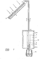
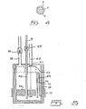
- the system illustrated in FIG. 1 comprises a solar collector 2 provided with an absorber 1.
- the fluid contained in the absorber 1 of the collector 2 is brought to a boil.
- the mixture of vapor and liquid generated in the absorber escapes by a pipe 3 in a separator 4.
- the vapor is free to circulate in the free part of the separator 4 while the liquid falls by gravity at the bottom of the separator 4 to return to the base of the absorber 1 of the sensor 2 via a pipe 5.
- the steam escapes from the separator 4 through an outlet pipe 6 to condense in a heat exchanger 7 placed at the end of the pipe 6.
- the separator 4 is a tank whose liquid retention capacity below the limit level 8 corresponding to the height at which the pipe 6 is located, is equal to at least half the volume of liquid which the absorber 1 of the sensor 2 can contain.
- the return of the condensed liquid to the separator 4 is done by a pipe 9 concentric with the pipe 6 used to convey the steam to the exchanger 7.
- An insulating sheath 10 encloses the whole as as illustrated in figure 4.
- the heat exchanger 7 is a concentric single or double wall chimney of the type used in insulated water heaters powered by fuels.
- the conden The vaporization takes place on the internal wall 12 of the exchanger 7, the vapor transferring its heat of condensation by conduction through the wall of the exchanger then by convection with water from the tank 11.
- the liquid 13 resulting from condensation then accumulates at the base of the exchanger 7.
- a pump 14 is finally provided for returning the liquid 13 to the separator 4 via the pipe 9.
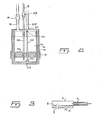
- the pump 14 consists of two concentric containers 15-16 separated between them, leaving a small accessible volume between their walls.
- the outer container 15 which is hermetically closed, is made of a conductive metal allowing the heating element 17 in the form of a sleeve to transmit its heat to it.
- the external container 15 is connected to the exchanger 7 by a liquid inlet 18 provided with a valve 19, as well as by a steam valve comprising a movable needle 20, an opening 21 and an exhaust tube 22.
- the inlet 18 is placed so that the incoming liquid falls by gravity into the internal container.
- the internal container 16 is made of an insulating material. This container 16 has at its base an opening 23 through which liquid can escape to fill the volume between the walls of the two concentric containers 15-16. In the absence of liquid in the reservoir 16, this opening is obstructed by a needle 24 connected to the upper needle 20 by a rod 25 passing through a float 26.
- the pipes connecting the separator 4 to the exchanger 7 and to the pump 14 of the system can be parallel instead of being concentric.
- the part of the liquid to be vaporized within the pump can be withdrawn by other means, such as by siphoning through a siphon 29 which starts automatically as soon as the liquid level has reached a predetermined value.
- the float 26 continues to serve to close the steam valve 21 when the level rises in the internal tank and to open the latter when the accumulated liquid has been expelled.
Landscapes
- Engineering & Computer Science (AREA)
- General Engineering & Computer Science (AREA)
- Thermal Sciences (AREA)
- Mechanical Engineering (AREA)
- Physics & Mathematics (AREA)
- Chemical & Material Sciences (AREA)
- Combustion & Propulsion (AREA)
- Life Sciences & Earth Sciences (AREA)
- Sustainable Development (AREA)
- Sustainable Energy (AREA)
- Engine Equipment That Uses Special Cycles (AREA)
- Steam Or Hot-Water Central Heating Systems (AREA)
- Heat-Pump Type And Storage Water Heaters (AREA)
Applications Claiming Priority (2)
| Application Number | Priority Date | Filing Date | Title |
|---|---|---|---|
| CA427562 | 1983-05-06 | ||
| CA000427562A CA1227978A (fr) | 1983-05-06 | 1983-05-06 | Systeme de chauffage solaire par changement de phases |
Publications (2)
| Publication Number | Publication Date |
|---|---|
| EP0125985A2 true EP0125985A2 (de) | 1984-11-21 |
| EP0125985A3 EP0125985A3 (de) | 1986-04-30 |
Family
ID=4125183
Family Applications (1)
| Application Number | Title | Priority Date | Filing Date |
|---|---|---|---|
| EP84400923A Withdrawn EP0125985A3 (de) | 1983-05-06 | 1984-05-04 | Sonnenheizsystem |
Country Status (7)
| Country | Link |
|---|---|
| EP (1) | EP0125985A3 (de) |
| JP (1) | JPS59208351A (de) |
| AU (1) | AU2756484A (de) |
| CA (1) | CA1227978A (de) |
| ES (1) | ES8600805A1 (de) |
| GR (1) | GR81606B (de) |
| IL (1) | IL71742A0 (de) |
Cited By (3)
| Publication number | Priority date | Publication date | Assignee | Title |
|---|---|---|---|---|
| AU657340B2 (en) * | 1991-08-07 | 1995-03-09 | Solahart Industries Pty Ltd | A gas booster apparatus for a tank of a solar hot water heater |
| WO2007109899A1 (en) * | 2006-03-28 | 2007-10-04 | Menova Energy Inc. | Energy supply system |
| ES2677269A1 (es) * | 2017-01-31 | 2018-07-31 | Jesús LUCAS PUERTO | Sistema de transmisión térmica bifásica |
Families Citing this family (1)
| Publication number | Priority date | Publication date | Assignee | Title |
|---|---|---|---|---|
| CN105509985B (zh) * | 2015-11-17 | 2016-11-16 | 江苏科技大学 | 海洋平台的t型管节点冲击试验装置及方法 |
Family Cites Families (5)
| Publication number | Priority date | Publication date | Assignee | Title |
|---|---|---|---|---|
| US4340030A (en) * | 1974-04-02 | 1982-07-20 | Stephen Molivadas | Solar heating system |
| US4044948A (en) * | 1975-10-17 | 1977-08-30 | Refrigeration Research, Inc. | Solar heating system component |
| CH618005A5 (en) * | 1977-04-21 | 1980-06-30 | Zutter Joe Kurt | Method for charging a thermal treatment device with a medium, and ductwork for carrying it out |
| US4220138A (en) * | 1978-01-24 | 1980-09-02 | Bottum Edward W | Refrigerant charged solar heating structure and system |
| US4256090A (en) * | 1979-10-01 | 1981-03-17 | Alessandro Imperiale | Solar heating system |
-
1983
- 1983-05-06 CA CA000427562A patent/CA1227978A/fr not_active Expired
- 1983-07-05 JP JP58122257A patent/JPS59208351A/ja active Pending
-
1984
- 1984-05-01 AU AU27564/84A patent/AU2756484A/en not_active Abandoned
- 1984-05-03 IL IL71742A patent/IL71742A0/xx unknown
- 1984-05-04 GR GR74593A patent/GR81606B/el unknown
- 1984-05-04 ES ES532685A patent/ES8600805A1/es not_active Expired
- 1984-05-04 EP EP84400923A patent/EP0125985A3/de not_active Withdrawn
Cited By (3)
| Publication number | Priority date | Publication date | Assignee | Title |
|---|---|---|---|---|
| AU657340B2 (en) * | 1991-08-07 | 1995-03-09 | Solahart Industries Pty Ltd | A gas booster apparatus for a tank of a solar hot water heater |
| WO2007109899A1 (en) * | 2006-03-28 | 2007-10-04 | Menova Energy Inc. | Energy supply system |
| ES2677269A1 (es) * | 2017-01-31 | 2018-07-31 | Jesús LUCAS PUERTO | Sistema de transmisión térmica bifásica |
Also Published As
| Publication number | Publication date |
|---|---|
| GR81606B (de) | 1984-12-11 |
| AU2756484A (en) | 1984-11-08 |
| ES532685A0 (es) | 1985-10-16 |
| EP0125985A3 (de) | 1986-04-30 |
| ES8600805A1 (es) | 1985-10-16 |
| JPS59208351A (ja) | 1984-11-26 |
| CA1227978A (fr) | 1987-10-13 |
| IL71742A0 (en) | 1984-09-30 |
Similar Documents
| Publication | Publication Date | Title |
|---|---|---|
| US4603685A (en) | Solar heating system | |
| EP2032440A1 (de) | Passives kapillargepumptes diphasisches flüssigkeitskreis-wärmesteuerungsgerät mit wärmeleistung | |
| EP0038769B1 (de) | Verfahren und Anlagen, um ein Wärmetauschfluidum in einem mit einer Wärmequelle und einer Kältequelle versehenen geschlossenen Kreislauf umlaufen zu lassen | |
| FR2477687A1 (fr) | Collecteur pour appareil de captage d'energie solaire et procede de captage d'energie solaire en discontinu a l'aide d'un appareil de captage d'energie solaire comportant ce collecteur | |
| EP1987292B1 (de) | Für heiz- oder luftklimatisierungssysteme bestimmte wärmetauschervorrichtung | |
| EP2306116B1 (de) | Thermische Solareinrichtung mit Schwerkraftentleerung | |
| GB2032613A (en) | Heat transfer system | |
| FR2610671A1 (fr) | Moteur a cycle thermodynamique a caloduc | |
| EP3004773A1 (de) | Wärmetransportvorrichtung mit zweiphasiger flüssigkeit | |
| CH699989A2 (fr) | Installation de chauffage domestique munie d'une pompe a chaleur. | |
| WO2023025678A1 (fr) | Dispositif de stockage d'energie et de production d'eau douce | |
| EP3274639B1 (de) | Solare einrichtung zur autonomen adsorptionskälteherstellung | |
| CA1227978A (fr) | Systeme de chauffage solaire par changement de phases | |
| CH660072A5 (fr) | Installation de chauffage d'un liquide. | |
| FR2575811A1 (fr) | Ensemble capteur-stockeur pour le chauffage d'eau par energie solaire | |
| EP0166661A2 (de) | Vorrichtung zum Auffangen und Fortleiten von Strahlungsenergie wie Sonnenstrahlung | |
| FR2604370A1 (fr) | Dispositif et procede pour le piegeage thermo-electrique de vapeur. | |
| EP0767081B1 (de) | Wärmerückgewinnungsanlage aus Fahrzeugabgasen | |
| FR2615569A1 (fr) | Pompe atmospherique autonome solaire | |
| WO2014181047A1 (fr) | Dispositif de capture, d'échange et de stockage thermique de l'énergie solaire | |
| FR2718491A1 (fr) | Dispositif de récupération d'énergie sur échappement de moteurs thermiques. | |
| EP2981781A1 (de) | Wärmerohr mit abgeschirmtem gasstecker | |
| FR2938636A1 (fr) | Condenseur perfectionne destine a assurer le transfert de calories entre un fluide frigorigene et un fluide caloporteur | |
| BE893310A (fr) | Dispositif d'accumulation et d'utilisation de la chaleur solaire | |
| FR2926351A1 (fr) | Dispositif de chauffage de l'eau |
Legal Events
| Date | Code | Title | Description |
|---|---|---|---|
| PUAI | Public reference made under article 153(3) epc to a published international application that has entered the european phase |
Free format text: ORIGINAL CODE: 0009012 |
|
| AK | Designated contracting states |
Designated state(s): AT BE DE FR GB IT NL |
|
| PUAL | Search report despatched |
Free format text: ORIGINAL CODE: 0009013 |
|
| AK | Designated contracting states |
Kind code of ref document: A3 Designated state(s): AT BE DE FR GB IT NL |
|
| STAA | Information on the status of an ep patent application or granted ep patent |
Free format text: STATUS: THE APPLICATION IS DEEMED TO BE WITHDRAWN |
|
| 18D | Application deemed to be withdrawn |
Effective date: 19861203 |
|
| RIN1 | Information on inventor provided before grant (corrected) |
Inventor name: RHEAULT, FERNAND Inventor name: JEAN, BENOIT Inventor name: BERGEVIN, BENOIT |