EP0126140B1 - Mecanisme de pression pneumatique variable - Google Patents
Mecanisme de pression pneumatique variable Download PDFInfo
- Publication number
- EP0126140B1 EP0126140B1 EP83903862A EP83903862A EP0126140B1 EP 0126140 B1 EP0126140 B1 EP 0126140B1 EP 83903862 A EP83903862 A EP 83903862A EP 83903862 A EP83903862 A EP 83903862A EP 0126140 B1 EP0126140 B1 EP 0126140B1
- Authority
- EP
- European Patent Office
- Prior art keywords
- section
- rigid
- pneumatic chamber
- mounting
- stem
- Prior art date
- Legal status (The legal status is an assumption and is not a legal conclusion. Google has not performed a legal analysis and makes no representation as to the accuracy of the status listed.)
- Expired
Links
- 230000007246 mechanism Effects 0.000 title claims abstract description 24
- 239000002131 composite material Substances 0.000 claims abstract description 9
- 230000008602 contraction Effects 0.000 claims description 12
- 230000007423 decrease Effects 0.000 claims description 3
- 230000000694 effects Effects 0.000 description 4
- 239000011324 bead Substances 0.000 description 3
- 238000010276 construction Methods 0.000 description 3
- 238000004891 communication Methods 0.000 description 2
- 238000005096 rolling process Methods 0.000 description 2
- 238000007789 sealing Methods 0.000 description 2
- 230000003190 augmentative effect Effects 0.000 description 1
- 238000002788 crimping Methods 0.000 description 1
- 210000005069 ears Anatomy 0.000 description 1
- 229920001971 elastomer Polymers 0.000 description 1
- 238000009434 installation Methods 0.000 description 1
- 238000012423 maintenance Methods 0.000 description 1
- 239000000463 material Substances 0.000 description 1
- 238000012856 packing Methods 0.000 description 1
- 239000005060 rubber Substances 0.000 description 1
- 229920003051 synthetic elastomer Polymers 0.000 description 1
- 239000005061 synthetic rubber Substances 0.000 description 1
Images

Classifications
-
- F—MECHANICAL ENGINEERING; LIGHTING; HEATING; WEAPONS; BLASTING
- F01—MACHINES OR ENGINES IN GENERAL; ENGINE PLANTS IN GENERAL; STEAM ENGINES
- F01B—MACHINES OR ENGINES, IN GENERAL OR OF POSITIVE-DISPLACEMENT TYPE, e.g. STEAM ENGINES
- F01B19/00—Positive-displacement machines or engines of flexible-wall type
- F01B19/04—Positive-displacement machines or engines of flexible-wall type with tubular flexible members
Definitions
- Our invention relates to a variable pneumatic pressure mechanism which includes a flexible pneumatic chamber which is contractable and extensible.
- a pneumatic pressure mechanism to which the present invention relates is particularly suited for exerting pressure on the barking arms of a mechanical log barker of the type shown in US-A-3190327, which issued on June 22, 1965 in the name of Robbins, or US-A-3137329, which issued on June 16, 1964 in the name of Smith, for example.
- Each of the pneumatic actuators for a barking arm of the log barker disclosed in US-A-3190327 includes a sector-shaped pneumatic chamber through which swings a rectangular vane that is connected to the barking arm. It is difficult to seal the edges of such vanes relative to the walls of the pneumatic chamber.
- the barking arm actuators disclosed in US-A-3137329 include pneumatic chambers in the form of hoses that bear on shoes connected to the barker arms, but such pneumatic chambers are capable of only very limited change in volume for moving such shoes and the hoses undoubtedly would be subject to quite rapid fatigue.
- Flexible pneumatic chambers of generally circular cross-section which can be contracted and extended have been used for various purposes but they have not been suitable for use under conditions where they would be susceptible to excessive buckling during contraction because the resultant repeated def ormation during use would cause rapid fatigue.
- US-A-3525289 discloses a pneumatic actuator for operating a valve by rotation of the valve about a central shaft.
- the actuator comprises the combination of a force-transmitting member or link, a radial arm which is fixed to the shaft and which is pivotally connected to the link, and a composite pneumatic chamber having a rigid section, a reciprocable assembly or mounting at one end which is pivotally connected to the link whereby to impart arcuate movement to the link as it reciprocates, and a rolling diaphragm by which the reciprocable assembly is connected to the rigid section.
- the reciprocable assembly is constrained for rectilinear movement by a rod which emerges from it at both ends, and which is fixed at both ends within structure which forms the rigid section.
- the actuator is not suitable for imparting arcuate movement to a force-transmitting member through a pivot connection which must move nonlinearly relative to the reciprocable assembly. Also a seal between the rod and the reciprocable assembly
- a variable pneumatic pressure force-transmitting mechanism comprising the combination of a forcetransmitting member, pivot means mounting the force-transmitting member for arcuate movement, a closed composite pneumatic chamber including a reciprocable mounting pivotally connected to the force-transmitting member, a rigid section remote from the mounting and a contractable and extensible section connected between the rigid section and the mounting, wherein attitude control means which does not pierce the wall of the pneumatic chamber is provided, the attitude control means bridging between the mounting and the rigid section and guiding the mounting for limited tilting relative to the rigid section as the spacing between the mounting and the rigid section decreases during contraction of the contractable and extensible section and arcuate movement of the forcetransmitting member about the pivot means.
- the present invention provides a mechanism for controlling or minimizing buckling of the flexible pneumatic chamber during contraction where one end of the chamber moves non-linearly and transmits mechanical force.
- Such buckling can be minimized by providing a cooperating guide stem carried by the force-transmitting mounting of the flexible chamber in which the stem extends generally axially through the flexible chamber, bridges it between its ends and is reciprocable through a guide aperture so as to permit limited relative tilting of the flexible mounting while preventing appreciable relative tilting of the chamber ends which would effect buckling of the flexible chamber.
- Variable pneumatic pressure mechanisms in which the present invention is embodied are illustrated as being employed as pressers for barker arms in a mechanical ring type of log barker.
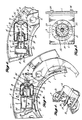
- a barker includes a ring 1 through which logs are transported lengthwise while the ring rotates relative to them to drag the inner ends of barker arms 2 spirally around the log to scrape bark from the log.
- the barking ends of arms 2 must be pressed with considerable force against the log.
- Pressers in which the present invention is embodied are utilized to apply force to the barker arms for producing such barking pressure and to receive force from the barker arms when they are swung outward by contact with a log.
- each barking arm 2 is mounted on an axle 3 which supports the arm for inward and outward swinging of its inner end to a degree conforming to the size of a log being barked.
- Each barking arm is biased to swing its inner barking end inward by pressure exerted on the lever arm 4 projecting generally outward from the outer end of the barking arm.
- the variable pneumatic pressure mechanism which embodies the present invention exerts a force on such lever arm to effect such swinging.
- the variable pneumatic presser 5 includes a composite pneumatic pressure chamber including a rigid pressure chamber section 6 which may have an auxiliary rigid reservoir 7 and a contractable and extensible section 8 which sections are always in communication with each other.
- the contractable and extensible section of the pneumatic chamber is a flexible air bag which is connected between the rigid pneumatic chamber section 6 and a mounting 9.
- the flexible air bag 8 is generally cylindrical, being of circular cross section, and having central apertures in its opposite ends.
- the aperture in one of such ends has an annular bead 10 that will bear tightly in sealing engagement against the shoulder formed by the annular flange 11 on mounting 9 which encircles a central boss 12 so that such mounting forms one end of the contractable and extensible section.
- the other end 13 of the bag is recurved to provide an inturned end portion 14 of smaller diameter than the central portion of the bag and having an annular bead 15 encircling its aperture.
- Such bead will fit tightly in sealing engagement against a shoulder 16 formed on the adjacent end of the rigid pneumatic chamber section 6 by an axial flange 17 projecting from such chamber end.
- the axial opening 18 within such axial flange affords communication between the interior of the rigid pneumatic chamber section 16 and the contractable and extensible chamber section 8.
- the axial opening 18 further provides a passage for an axial cantilever stem 19 of bag attitude control means, the base of which is anchored in the inner side of the mounting 9 so that such stem bridges across the flexible chamber section 8 between such mounting and the rigid chamber section 6.
- the free end portion of such stem extends through a guide aperture 20 in the central portion of a transverse frame 21 spanning the interior of the rigid pneumatic chamber section 6.
- Such frame has ports 22 extending through it between its central aperture 20 and the wall of the rigid chamber section so as to afford substantially unobstructed interchange of air between the portions of the rigid pneumatic chamber section on opposite sides of such frame.
- the control stem 19 is located completely within the composite pneumatic chamber and consequently does not pierce the wall of the composite chamber, thus avoiding the necessity of any packing joints around the stem.
- the pneumatic presser mechanism 5 of the type shown in Figures 1, 2 and 3 can be installed within the barker ring 1 by attaching ears 23 formed on the auxiliary rigid pneumatic pressure chamber reservoir 7 to the barker ring by bolts or machine screws 24.
- the other end of the pneumatic chamber formed by the mounting 9 is attached to the lever arm 4 of a barker arm 2 by connecting a lug 25 projecting from the mounting to such lever arm by a pivot pin 26, so that such pivot pin and the lug 25 are guided to move non- linearly by the non-linear swinging of lever arm 4 about the center of axle 3.
- the pivot 26 connection can transmit force between the barking arm 2 and the presser mechanism 5 in either direction.
- all of the rigid pneumatic chamber sections in the barker ring be interconnected by a conduit 27, although such interconnection is not necessary.
- An initial pressure may be established in all of the pneumatic chambers equally by supplying air under pressure to the fitting 28 of such conduit.
- each pressure chamber can be precharged with air separately, but such interconnection is preferred to ensure initial equalization of pressure in the several chambers and to ensure continued equalization of pressure if a log is not precisely centered within the ring 1 or if the log has irregularities on it which may effect somewhat unequal swinging of the barking arms relative to the barker ring.
- the initial pressure in the pneumatic chambers of the pressers will extend the flexible bags 8 to their maximum central axial extent for exerting force on the lever arms 4 to swing the barker arms inward to the positions illustrated in Figure 1.
- the barker ring 1 is turning in the counterclockwise direction indicated in Figure 1 as a log is advanced lengthwise into the ring aperture, the sharpened edges of the barking arms 2 will contact the log end and the rotation of the ring will cause the inner ends of the barking arms to swing outward in a self -opening operation until the inner ends of the arms engage the periphery of the log.
- Such outward swinging of the barking arms will effect swinging of the lever arms 4 in a direction to exert force on the pivots 26, lugs 25 and mounting 9 to contract the pressers 5 generally axially.
- the transverse size of the rigid pneumatic chamber section 6 is sufficiently smaller than the cross-sectional size of the larger central portion of the flexible bag 8 that, when the central axial extent of the flexible bag is contracted from the condition of Figure 1 toward the condition of Figure 2, the inturned end portion 14 of the flexible bag will roll over the exterior of the rigid pneumatic chamber section 6 to increase the axial extent of the inturned bag portion 14, shift the axial position of the reverted bag portion 13 and decrease the axial extent of the outer portion of the bag.
- the size of the rigid pneumatic chamber section 6 should be sufficiently smaller than the size of the larger cross-sectional portion of the flexible bag so that the reverted portion of the flexible bag will be curved easily to reduce a stress concentration area that would contribute greatly to the fatigue of the flexible material such as rubber or synthetic rubber.
- the present invention provides bag attitude control means utilizing the cooperation of the cantilever stem 19 with the guide aperture 20 through which it extends to control the attitude of the flexible bag 8 so that its walls are subjected to substantially uniform conditions and stresses throughout its contraction movement despite the non-linear movement of pivot pin 26. Because pivot pin 26 will travel in an arcuate path about the center of the barking arm axle 3 as the arm swings, the lug 25 and mounting 9 cannot be restricted to linear reciprocation if the rigid chamber section 6 is fixed to the barker ring 1.
- the bag attitude control means allows the lug and mounting to be tilted to a small extent relative to the rigid chamber section 6 during contraction of the bag 8 from the condition shown in Figure 1 to that of Figure 5. Movement of the lug pivot 26 laterally of stem 19 will cause slight angular movement or tilting of the stem 19 generally about the center of the guide aperture 20 through which the stem extends.
- the aperture 20 can be made somewhat larger than the portion of the stem that reciprocates through it because the aperture is not required to seal about the stem.
- the stem can have a diameter of 2.2 cm (7/8 inch) while the aperture 20 may have a diameter of 2.4 cm (15/16 inch).
- the guide aperture 20 may flare toward the root of the stem and be tapered toward the tip of the stem, which would reduce the lateral play of the stem in such aperture.
- the cooperation of such stem and aperture will control the reciprocating movement of the mounting 9 relative to the rigid section 6 of the pneumatic chamber so as to limit tilting of the mounting relative to the rigid chamber to a small amount and, consequently, such cooperation will hold the flexible bag 8 in condition of substantially uniform rolling of its inturned portion on the exterior of the rigid chamber section 6 as the flexible bag contracts from the position from Figure 1 to the position of Figure 2.
- the initial or precharged pressure of the pneumatic system, or of each individual presser may be such that the force exerted may be from 11.34 kg (25 lbs) to 45.36 kg (100 lbs).
- contraction of each flexible bag 8 will reduce the volume of the pneumatic chamber and increase the pressure in it.
- the force exerted by the system may be increased from the initial force range of 11.34 kg (25 Ibs) to 45.36 kg (100 lbs) to a maximum force range of 22.68 kg (50 lbs) to 72.57 kg (160 lbs).
- the collective volume of the flexible bags 8 may be from 20 percent to 80 percent of the total volume of the pneumatic system.
- conduit 27 interconnecting the pneumatic chambers of the several pressers can be omitted, or individual valves may be provided at each pressure chamber connection that can be closed to effectively remove the conduit 27 from the system after precharging of the pneumatic chambers has been accomplished.
- the degree of force increase effected by contraction of the bags 8 can be augmented by increasing the volumetric proportion of each flexible bag 8 relative to the combined volume of such flexible bag and the associated rigid pneumatic chamber 7.
- the length of the rigid chamber relative to the flexible bag must, however, be great enough so that the rigid chamber will accommodate the stem 19 throughout its lengthwise stroke corresponding to full movement of the flexible bag mounting 9 between maximum and minimum volumes of the flexible bag.
- Such objective can be accomplished by the construction shown in Figure 5 in which the auxiliary rigid pressure chamber section 7 has been deleted in favour of an end wall 29 on which the rigid pneumatic chamber section 6 is mounted.
- the stem 19' of Figure 5 is shorter than the stem 19 of Figures 1 and 2 and the guide aperture frame 21 has been moved away f rom the end plate 29 to a position close to the opposite end wall of the rigid pneumatic chamber section. Except for the greater pressure build-up that will be accomplished in the pneumatic chamber for a given degree of swinging of a barking arm 2 and its lever arm 4, the operation of the presser and its bag attitude control mechanism shown in Figure 5 will be similar to the operation of the mechanism shown in Figures 1 and 2, as described in detail above.
- the mechanism shown in Figure 6 provides attitude control for the flexible bag 8 during its contraction movement effected by outward swinging of the barking arm 2 and consequent swinging of the lever arm 4 even though the rigid pneumatic chamber section 6' and the auxiliary rigid reservoir 7' are not fixedly mounted to the barker ring 1.
- the rigid pneumatic chamber portions 6' and 7' are capable of swinging relative to the lever arm 4 because they are attached to the barker ring by a lug 30 projecting from the auxiliary reservoir 7' connected by pivot pin 31 to the barker ring.
- Buckling of the flexible pneumatic chamber section 8 in this instance is eliminated by the cantilever stem 32 having its root anchored in mounting 9 and projecting axially through apertures in two frames 33 and 36 spaced apart lengthwise of such stem and of the rigid pneumatic chamber section 6'.
- One of these frames 33 is located close to the opening 18 in the end of the rigid pneumatic chamber section nearer mounting 9.
- Such frame 33 has the guide aperture 34 in its central portion and pressure-equalizing apertures 35 arranged around such guide aperture.
- the second frame 36 Spaced from the frame 33 a distance lengthwise of stem 32 sufficient to provide stability for the stem guidance, is the second frame 36 having in it a central guide aperture through which the stem 32 extends and pressure-equalizing apertures 37, 38 located between the guide aperture 37 and the wall of the rigid pneumatic chamber section 6'.
- the aligned apertures 34 and 37 of the frames 33 and 36, respectively, will guide the stem 32 for precisely linear reciprocation relative to the rigid chamber section irrespective of swinging movement of the presser about its pivot 31 effected by the throw of the lever arm 4.
- the guide apertures 34 and 37 might be of a size to fit the stem 32 with snug sliding fits.
Landscapes
- Engineering & Computer Science (AREA)
- Mechanical Engineering (AREA)
- General Engineering & Computer Science (AREA)
- Paper (AREA)
- Actuator (AREA)
- Soil Working Implements (AREA)
- Steering Control In Accordance With Driving Conditions (AREA)
- Auxiliary Devices For And Details Of Packaging Control (AREA)
- Debarking, Splitting, And Disintegration Of Timber (AREA)
- Road Paving Machines (AREA)
- Finger-Pressure Massage (AREA)
- Eye Examination Apparatus (AREA)
- Pens And Brushes (AREA)
- Thin Film Transistor (AREA)
- Braking Arrangements (AREA)
- Invalid Beds And Related Equipment (AREA)
- Massaging Devices (AREA)
Claims (4)
Priority Applications (1)
| Application Number | Priority Date | Filing Date | Title |
|---|---|---|---|
| AT83903862T ATE25537T1 (de) | 1982-11-29 | 1983-11-04 | Mechanismus fuer variablen luftdruck. |
Applications Claiming Priority (2)
| Application Number | Priority Date | Filing Date | Title |
|---|---|---|---|
| US444955 | 1982-11-29 | ||
| US06/444,955 US4566371A (en) | 1982-11-29 | 1982-11-29 | Variable pneumatic pressure force-transmitting mechanism |
Publications (3)
| Publication Number | Publication Date |
|---|---|
| EP0126140A1 EP0126140A1 (fr) | 1984-11-28 |
| EP0126140A4 EP0126140A4 (fr) | 1985-06-06 |
| EP0126140B1 true EP0126140B1 (fr) | 1987-02-25 |
Family
ID=23767060
Family Applications (1)
| Application Number | Title | Priority Date | Filing Date |
|---|---|---|---|
| EP83903862A Expired EP0126140B1 (fr) | 1982-11-29 | 1983-11-04 | Mecanisme de pression pneumatique variable |
Country Status (12)
| Country | Link |
|---|---|
| US (1) | US4566371A (fr) |
| EP (1) | EP0126140B1 (fr) |
| JP (1) | JPS59502096A (fr) |
| AT (1) | ATE25537T1 (fr) |
| AU (1) | AU563500B2 (fr) |
| BR (1) | BR8307630A (fr) |
| CA (1) | CA1203739A (fr) |
| DE (1) | DE3369867D1 (fr) |
| FI (1) | FI76184C (fr) |
| NZ (1) | NZ206420A (fr) |
| WO (1) | WO1984002159A1 (fr) |
| YU (1) | YU233583A (fr) |
Cited By (1)
| Publication number | Priority date | Publication date | Assignee | Title |
|---|---|---|---|---|
| US8215347B2 (en) | 2008-10-03 | 2012-07-10 | Fpinnovations | Apparatus and methods for controlled debarking of wood |
Families Citing this family (8)
| Publication number | Priority date | Publication date | Assignee | Title |
|---|---|---|---|---|
| US4844201A (en) * | 1987-04-29 | 1989-07-04 | Nicholson Manufacturing Company | Recirculating oil lubrication system for rotary ring log barkers |
| US5097880A (en) * | 1991-04-26 | 1992-03-24 | Valon Kone Brunette, Ltd. | Rotary log debarker with improved air management system |
| BR0307678A (pt) * | 2002-02-20 | 2007-02-21 | Danzer North America Inc | aparelho para aplainar um desdobro de madeira |
| US7350548B1 (en) | 2006-10-16 | 2008-04-01 | Nicholson Manufacturing Ltd. | Swing arm assembly with replaceable insert for use with a debarker apparatus |
| US7743805B2 (en) * | 2007-06-13 | 2010-06-29 | Nicholson Manufacturing Ltd. | Debarking tip assembly with replaceable cutting element |
| US7806153B2 (en) * | 2008-01-15 | 2010-10-05 | Reimler James L | Log debarking blade |
| US7931055B2 (en) | 2009-02-10 | 2011-04-26 | Reimler James L | Log debarking tool and tool tip |
| US9073233B2 (en) | 2011-05-31 | 2015-07-07 | Nicholson Manufacturing Ltd. | Debarker systems with adjustable rings |
Family Cites Families (13)
| Publication number | Priority date | Publication date | Assignee | Title |
|---|---|---|---|---|
| US2829500A (en) * | 1954-12-03 | 1958-04-08 | Dunlop Rubber Co | Fluid pressure actuated system and operating means therefor |
| US2927431A (en) * | 1958-03-19 | 1960-03-08 | Jersey Prod Res Co | Valve for diaphragm pump |
| US3190327A (en) * | 1959-11-30 | 1965-06-22 | Nicholson Mfg Company | Log barker with vane-actuated barking arms |
| FR1316410A (fr) * | 1962-03-01 | 1963-01-25 | Honeywell Regulator Co | Organe de manoeuvre pneumatique |
| US3137329A (en) * | 1962-10-18 | 1964-06-16 | Ederer Corp | Ring barker with pneumatic pressure operated debarking arms |
| US3361168A (en) * | 1965-11-30 | 1968-01-02 | Black Clawson Co | Log barker |
| US3386345A (en) * | 1966-08-01 | 1968-06-04 | John F. Taplin | Rolling diaphragm device having centering button on diaphragm and having piston rod rotatable relative to piston |
| US3525289A (en) * | 1969-02-18 | 1970-08-25 | United Aircraft Corp | Pneumatic actuator |
| US3624802A (en) * | 1970-06-29 | 1971-11-30 | Grove Valve & Regulator Co | Floating stem seal assembly |
| US3667517A (en) * | 1970-09-02 | 1972-06-06 | Black Clawson Co | Log barker |
| CA909114A (en) * | 1971-03-09 | 1972-09-05 | Canadian International Paper Company | Delimber |
| US4403538A (en) * | 1980-09-02 | 1983-09-13 | The Garrett Corporation | Turbocharger control actuator |
| US4502673A (en) * | 1982-02-11 | 1985-03-05 | Applied Power Inc. | Integral shock absorber and spring assembly |
-
1982
- 1982-11-29 US US06/444,955 patent/US4566371A/en not_active Expired - Fee Related
-
1983
- 1983-11-04 WO PCT/US1983/001732 patent/WO1984002159A1/fr not_active Ceased
- 1983-11-04 BR BR8307630A patent/BR8307630A/pt not_active IP Right Cessation
- 1983-11-04 DE DE8383903862T patent/DE3369867D1/de not_active Expired
- 1983-11-04 AU AU23303/84A patent/AU563500B2/en not_active Ceased
- 1983-11-04 EP EP83903862A patent/EP0126140B1/fr not_active Expired
- 1983-11-04 JP JP58503800A patent/JPS59502096A/ja active Granted
- 1983-11-04 AT AT83903862T patent/ATE25537T1/de not_active IP Right Cessation
- 1983-11-09 CA CA000440815A patent/CA1203739A/fr not_active Expired
- 1983-11-25 YU YU02335/83A patent/YU233583A/xx unknown
- 1983-11-28 NZ NZ206420A patent/NZ206420A/en unknown
-
1984
- 1984-07-27 FI FI843004A patent/FI76184C/fi not_active IP Right Cessation
Cited By (1)
| Publication number | Priority date | Publication date | Assignee | Title |
|---|---|---|---|---|
| US8215347B2 (en) | 2008-10-03 | 2012-07-10 | Fpinnovations | Apparatus and methods for controlled debarking of wood |
Also Published As
| Publication number | Publication date |
|---|---|
| FI843004A0 (fi) | 1984-07-27 |
| FI843004L (fi) | 1984-07-27 |
| EP0126140A4 (fr) | 1985-06-06 |
| DE3369867D1 (en) | 1987-04-02 |
| YU233583A (en) | 1988-02-29 |
| AU2330384A (en) | 1984-06-18 |
| JPS59502096A (ja) | 1984-12-20 |
| JPH027806B2 (fr) | 1990-02-21 |
| AU563500B2 (en) | 1987-07-09 |
| ATE25537T1 (de) | 1987-03-15 |
| CA1203739A (fr) | 1986-04-29 |
| BR8307630A (pt) | 1984-11-27 |
| WO1984002159A1 (fr) | 1984-06-07 |
| FI76184B (fi) | 1988-05-31 |
| FI76184C (fi) | 1988-09-09 |
| EP0126140A1 (fr) | 1984-11-28 |
| US4566371A (en) | 1986-01-28 |
| NZ206420A (en) | 1986-09-10 |
Similar Documents
| Publication | Publication Date | Title |
|---|---|---|
| EP0126140B1 (fr) | Mecanisme de pression pneumatique variable | |
| AU629600B2 (en) | Gate valve with supplemental actuator | |
| US4465441A (en) | Two-cylinder pump for heavy flowable materials, such as concrete | |
| US3857545A (en) | Valve for deep vacuum chambers | |
| US6257119B1 (en) | Ball joint for servo piston actuation in a bent axis hydraulic unit | |
| EP0382970A2 (fr) | Vanne à tiroir avec dispositif d'actionnement supplémentaire | |
| US4260129A (en) | Rotary spherical plug valve | |
| CA1133451A (fr) | Robinet a clapet avec raccord axial | |
| US4231545A (en) | High pressure ball valve with tipping action | |
| US4792118A (en) | Low dead space ring | |
| US5127428A (en) | Poppet valve assembly and method of making same | |
| GB2184212A (en) | Valve | |
| US5005602A (en) | Poppet valve assembly | |
| US4174825A (en) | Ball valve with reciprocal and rotatable spindle | |
| JPH0243944B2 (fr) | ||
| NO314957B1 (no) | Anordning til overföring av bevegelser og en ventil omfattende en sådan | |
| GB2037402A (en) | Vlave spindle sealing arrangement | |
| KR940008828B1 (ko) | 관절(knuckle)의 회전운동을 위한 유압 작동기 | |
| US6742954B2 (en) | Locking system for a rotating joint | |
| US3027909A (en) | Fluid control valves | |
| EP0442972B1 (fr) | Vanne papillon sans tige | |
| US4085660A (en) | Pivotal support for a fluid actuated cylinder with means for communicating pressurized fluid thereto | |
| US2529431A (en) | Power-operated valve | |
| GB1572436A (en) | Shut-off flap valve | |
| US4426195A (en) | Adjustable axial flow piston machines |
Legal Events
| Date | Code | Title | Description |
|---|---|---|---|
| PUAI | Public reference made under article 153(3) epc to a published international application that has entered the european phase |
Free format text: ORIGINAL CODE: 0009012 |
|
| AK | Designated contracting states |
Designated state(s): AT BE CH DE FR GB LI LU SE |
|
| 17P | Request for examination filed |
Effective date: 19841025 |
|
| GRAA | (expected) grant |
Free format text: ORIGINAL CODE: 0009210 |
|
| AK | Designated contracting states |
Kind code of ref document: B1 Designated state(s): AT BE CH DE FR GB LI LU SE |
|
| REF | Corresponds to: |
Ref document number: 25537 Country of ref document: AT Date of ref document: 19870315 Kind code of ref document: T |
|
| REF | Corresponds to: |
Ref document number: 3369867 Country of ref document: DE Date of ref document: 19870402 |
|
| ET | Fr: translation filed | ||
| PG25 | Lapsed in a contracting state [announced via postgrant information from national office to epo] |
Ref country code: LU Free format text: LAPSE BECAUSE OF NON-PAYMENT OF DUE FEES Effective date: 19871130 |
|
| PLBE | No opposition filed within time limit |
Free format text: ORIGINAL CODE: 0009261 |
|
| STAA | Information on the status of an ep patent application or granted ep patent |
Free format text: STATUS: NO OPPOSITION FILED WITHIN TIME LIMIT |
|
| 26N | No opposition filed | ||
| PGFP | Annual fee paid to national office [announced via postgrant information from national office to epo] |
Ref country code: GB Payment date: 19901023 Year of fee payment: 8 |
|
| PGFP | Annual fee paid to national office [announced via postgrant information from national office to epo] |
Ref country code: SE Payment date: 19901114 Year of fee payment: 8 |
|
| PGFP | Annual fee paid to national office [announced via postgrant information from national office to epo] |
Ref country code: CH Payment date: 19901203 Year of fee payment: 8 |
|
| PG25 | Lapsed in a contracting state [announced via postgrant information from national office to epo] |
Ref country code: GB Effective date: 19911104 |
|
| PG25 | Lapsed in a contracting state [announced via postgrant information from national office to epo] |
Ref country code: SE Effective date: 19911105 |
|
| PG25 | Lapsed in a contracting state [announced via postgrant information from national office to epo] |
Ref country code: LI Effective date: 19911130 Ref country code: CH Effective date: 19911130 |
|
| GBPC | Gb: european patent ceased through non-payment of renewal fee | ||
| REG | Reference to a national code |
Ref country code: CH Ref legal event code: PL |
|
| EUG | Se: european patent has lapsed |
Ref document number: 83903862.7 Effective date: 19920604 |
|
| PGFP | Annual fee paid to national office [announced via postgrant information from national office to epo] |
Ref country code: DE Payment date: 19961108 Year of fee payment: 14 |
|
| PGFP | Annual fee paid to national office [announced via postgrant information from national office to epo] |
Ref country code: FR Payment date: 19961111 Year of fee payment: 14 |
|
| PGFP | Annual fee paid to national office [announced via postgrant information from national office to epo] |
Ref country code: AT Payment date: 19961114 Year of fee payment: 14 |
|
| PGFP | Annual fee paid to national office [announced via postgrant information from national office to epo] |
Ref country code: BE Payment date: 19961230 Year of fee payment: 14 |
|
| PG25 | Lapsed in a contracting state [announced via postgrant information from national office to epo] |
Ref country code: AT Free format text: LAPSE BECAUSE OF NON-PAYMENT OF DUE FEES Effective date: 19971104 |
|
| PG25 | Lapsed in a contracting state [announced via postgrant information from national office to epo] |
Ref country code: FR Free format text: THE PATENT HAS BEEN ANNULLED BY A DECISION OF A NATIONAL AUTHORITY Effective date: 19971130 Ref country code: BE Free format text: LAPSE BECAUSE OF NON-PAYMENT OF DUE FEES Effective date: 19971130 |
|
| BERE | Be: lapsed |
Owner name: NICHOLSON MFG CY Effective date: 19971130 |
|
| PG25 | Lapsed in a contracting state [announced via postgrant information from national office to epo] |
Ref country code: DE Free format text: LAPSE BECAUSE OF NON-PAYMENT OF DUE FEES Effective date: 19980801 |
|
| REG | Reference to a national code |
Ref country code: FR Ref legal event code: ST |