EP0126162B1 - Corps de chauffe pour le siege d'un vehicule - Google Patents
Corps de chauffe pour le siege d'un vehicule Download PDFInfo
- Publication number
- EP0126162B1 EP0126162B1 EP83903578A EP83903578A EP0126162B1 EP 0126162 B1 EP0126162 B1 EP 0126162B1 EP 83903578 A EP83903578 A EP 83903578A EP 83903578 A EP83903578 A EP 83903578A EP 0126162 B1 EP0126162 B1 EP 0126162B1
- Authority
- EP
- European Patent Office
- Prior art keywords
- seat
- heater
- vehicle
- thermostat
- temperature
- Prior art date
- Legal status (The legal status is an assumption and is not a legal conclusion. Google has not performed a legal analysis and makes no representation as to the accuracy of the status listed.)
- Expired
Links
- 238000010792 warming Methods 0.000 claims description 27
- 239000012774 insulation material Substances 0.000 claims description 7
- 239000011810 insulating material Substances 0.000 abstract 1
- 238000010438 heat treatment Methods 0.000 description 8
- 239000006185 dispersion Substances 0.000 description 4
- JOYRKODLDBILNP-UHFFFAOYSA-N Ethyl urethane Chemical compound CCOC(N)=O JOYRKODLDBILNP-UHFFFAOYSA-N 0.000 description 3
- 239000000758 substrate Substances 0.000 description 3
- 238000010586 diagram Methods 0.000 description 2
- 230000000694 effects Effects 0.000 description 2
- 238000002474 experimental method Methods 0.000 description 2
- 239000004744 fabric Substances 0.000 description 2
- 239000000463 material Substances 0.000 description 2
- 239000004745 nonwoven fabric Substances 0.000 description 2
- 238000013021 overheating Methods 0.000 description 2
- 239000000853 adhesive Substances 0.000 description 1
- 230000001070 adhesive effect Effects 0.000 description 1
- 230000007547 defect Effects 0.000 description 1
- 230000001419 dependent effect Effects 0.000 description 1
- 239000006260 foam Substances 0.000 description 1
- WABPQHHGFIMREM-UHFFFAOYSA-N lead(0) Chemical compound [Pb] WABPQHHGFIMREM-UHFFFAOYSA-N 0.000 description 1
- 239000010985 leather Substances 0.000 description 1
- 238000012423 maintenance Methods 0.000 description 1
- 229920000728 polyester Polymers 0.000 description 1
- 229920003002 synthetic resin Polymers 0.000 description 1
- 239000000057 synthetic resin Substances 0.000 description 1
- 238000003466 welding Methods 0.000 description 1
- 238000004804 winding Methods 0.000 description 1
Images



Classifications
-
- A—HUMAN NECESSITIES
- A47—FURNITURE; DOMESTIC ARTICLES OR APPLIANCES; COFFEE MILLS; SPICE MILLS; SUCTION CLEANERS IN GENERAL
- A47C—CHAIRS; SOFAS; BEDS
- A47C7/00—Parts, details, or accessories of chairs or stools
- A47C7/62—Accessories for chairs
- A47C7/72—Adaptations for incorporating lamps, radio sets, bars, telephones, ventilation, heating or cooling arrangements or the like
- A47C7/74—Adaptations for incorporating lamps, radio sets, bars, telephones, ventilation, heating or cooling arrangements or the like for ventilation, heating or cooling
- A47C7/748—Adaptations for incorporating lamps, radio sets, bars, telephones, ventilation, heating or cooling arrangements or the like for ventilation, heating or cooling for heating
Definitions
- This invention relates to a seat heater for vehicle which is to be mounted on at least one of seat cushion part and seat back part of seat for vehicle to carry out heating.
- seat heater main body 4 is configurated by wiring cord-shaped warming heater 2 in zig zag shape on substrate body 1 consisting of polyester nonwoven fabric, or the like, and by heat-press- bonding or the like means surface cloth 3 having thermal fusing adhesive is bonded by heat- pressing on both sides of the substrate body 1, and on one part of the seat heater main body 4 a thermostat 5 is mounted to directly sense the heat of the seat heater warming part 4', and furthermore, lead wires 6 are connected to the thermostat 5 and the above-mentioned warming heater 2, and connection plug 7 for connecting to a power source part (not shown) of an automobile is connected to the end part of the lead wires 6.
- the above-mentioned seat heater main body 4 is, as shown in FIG. 3, mounted on a seat part 8a and a seat back part 8b of a vehicle seat 8.
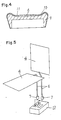
- the above-mentioned mounting of the seat heater main body is made, as shown in FIG. 4, by inserting and disposing it between a pad 9 formed by foamed urethane and a cushion material 10 made of foamed urethane.
- numeral 11 is a surface leather of vehicle seat.
- thermostat 5 to control electrification and diselectrification to the heater 2 by detecting the temperature of the warming heater 2 is mounted on one part of the seat heater main body 4, and the seat heater main body 4 is mounted in the vehicle seat 8, the thermostat 5 gives the user rugged feeling, and as a result, the user feels uncomfortable due to the thermostat 5 when seating on the vehicle seat 8.
- a control part which does not have an auxiliary heater.
- a thermostatic element is rather distant from a heating element. Therefore, a response of the thermostatic element to a change of temperature at the heating element is slow, and it is difficult to control a temperature of the heating element at a preset temperature.
- the present invention purposes to provide a seat heater for vehicles which does not cause uncomfortable feeling when the user is seated on the seat and is capable of controlling the warming heater in stable state independent of shape and state of the vehicle seat.
- the present invention covers the control part by heat insulation material, and also disposing the control part covered by the heat insulation material separating from seat heater main body to be mounted on at least one of seat cushion part and seat back part of the vehicle seat, and at a part other than the seat cushion part and seat back part of the vehicle seat.
- FIG. 1 is a perspective view showing the conventional seat heater for vehicle
- FIG. 2 is a cross-sectional view at A-A' line of FIG. 1
- FIG. 3 is the perspective view of the vehicle seat provided with the same seat heater
- FIG. 4 is the cross-sectional view at B-B' line of FIG. 3
- FIG. 5 is an exploded perspective view of a seat heater for vehicle showing one embodiment of the present invention
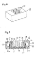
- FIG. 6 is a perspective view of a control part in the same seat heater
- FIG. 7 is a cross-sectional view of the same control part
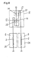
- FIG. 8 is a circuit diagram of the same seat heater
- FIG. 9 is a temperature vs. time characteristic chart of the same seat heater
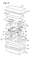
- FIG. 10 is an exploded perspective view of the seat heater showing another embodiment of the present invention
- FIG. 11 a and FIG. 11 b are side views of the same control device and cross-sectional view at c-c' line of FIG. 10, respectively
- FIG. 12 is an exploded perspective view of the same control
- FIG. 5 through FIG. 8 With respect to the same components the same numbers as those shown in FIG. 1 through FIG. 4 shown in the conventional example are designated, and different points from the conventional example only are elucidated. That is, in this embodiment, lead wires 6 to be connected to warming heater 2 are led out from a pair of seat heater main body 4 to be mounted on the seat cushion part 8a and seat back part 8b of the vehicle seat 8, and connection plugs 7 are provided at end parts of the lead wire 6, and a control part 12 to which the connection plugs 7 are detachably mounted and for stopping electrification to this heater when temperature of the warming heater 2 becomes above a preset temperature is provided.
- the control part 12 is provided as shown in FIG. 6 and FIG. 7 is comprised of thermostats 14 having temperature sensing parts 13, auxiliary heaters 17 disposed at adjacent positions to the thermostat 14 and constituted by winding cord-shaped heater around a holding body 16, a case 20 wherein this auxiliary heaters 17 and the above-mentioned thermostats 14 are mounted on a holding sheet 18 by a printed circuit substrate and which comprises a plug reception parts 19 in which the connection plugs 7 provided at the end parts of the above-mentioned lead wires 6 are detachably mounted, and a case lid 21 which is for closing a bottom opening of the case 20 and comprises protrusion part 21 a to abut the thermostats 14.
- the case 20 and the case lid 21 are of heat insulation material, and by these, the control part 12 is covered. Also, the above-mentioned thermostats 14 are mounted in the case 20 in a manner that the temperature sensing parts 13 abut the inside face of the case 20, and the auxiliary heaters 17 are disposed to heat parts located at opposite sides to the temperature sensing parts 13 of the thermostats 14.
- FIG. 8 shows circuit diagram, therein two thermostats 14 are connected in series, and the auxiliary heaters 17 are disposed adjacent to respective one of them to constitute thermostat-auxiliary heater units 22, 23, and furthermore, the above-mentioned auxiliary heaters 17 and a pair of warming heater 2 are connected in series respectively with connecting members. Incidentally, the pair of warming heater 2 and the auxiliary heaters 17 are respectively parallel connected.
- Seat cushion part sheet heater 24 to be mounted to the seat cushion 8a of the vehicle seat 8 corresponds to one thermally connected thermostat-auxiliary heater unit 22 and seat back part sheet heater 25 to be mounted at the seat back part 8b of the vehicle seat 8 corresponds to the other thermostat-auxiliary heater unit 23.
- the other thermostat-auxiliary heater unit normally operates.
- the two thermostats 14 are connected in series, the current flows through the two stage thermostats 14, and accordingly a double safety circuit can be constituted.
- control parts 12 which are constituted by the thermostats 14 or the like which stops electrification to the warming heater 2 when the temperature of the heater 2 becomes the preset temperature is covered by heat insulation material as above-mentioned, and they are disposed separated from the pair of sheet heater main body 4 to be mounted on the seat cushion part 8a and seat back part 8b of the vehicle seat 8 and at the part other than the seat cushion part 8a and the seat back part 8b of the vehicle seat 8, actually in a space below a pad 9 of FIG. 4.
- thermo-timer which receits on-off always with constant time t as shown by ⁇ of FIG. 9. That is, T of FIG. 9 shows the preset temperature, and a shows characteristic where time from rise of temperature to achieving of the present temperature of the thermostat is short, wherein there is a defect that utility feeling is spoiled; and y of FIG.
- connection plug 27 is provided on end parts of lead wires 26 led out from the control part 12, and it is detachably mounted with the connection plug 7 led out from a sheet heater main body 4. Also, a connection plug 28 of lead wires 26 is made so as to detachably mounted to power source connection plug 29 of lead wires 35 preliminarily led in from the vehicle or the like.
- the control part 12 is made such that as shown in FIG. 11 and FIG.
- auxiliary heater 17 for thermostat heating constituted by heat pressing cord-shaped heaters 15 by holding body 16 made of nonwoven fabric or the like and disinflammable fabrics 32 on holding bases 31 having holes 30 for inserting the thermostat 14, thereby one faces of the holes 30 of the holding bases 31 are closed.
- thermostats 14 having temperature sensing parts 13 are inserted in the holes 30 of the holding bases 31 which faces the auxiliary heater 17 for thermostat heating.
- the cord-shaped heater 15 led out from the auxiliary heater 17 for thermostat heating and the thermostats 14 are connected by lead wires 26, 36 and 37.
- the control part 12 is covered by heat insulation material such as the above-mentioned covering members 34, 39, 40, and is disposed under a pad 9.
- the electric circuit of this control part 12 is as shown in FIG. 8, and also, in the control part 12 the temperature rise characteristic of the thermostat 14 is determined by heat capacity and heat keeping states of the thermostats 14 and environments surrounding the thermostats. Of course, however, it should be considered to be dependent on the ambient temperature.
- the heat capacity can be determined by a product of weight and specific heat, according to experiments, weight of the thermostats 14 and weight of the holding bases 30 are, in total, preferably 20-25 g and the auxiliary heater 17 is preferably about 1 W-2 W, and thickness of the urethane foam covering member 34, 39, 40 is preferably 8-15 mm each and piling them in three layers, and appropriate ⁇ characteristic of FIG. 9 has been obtained.
- FIG. 5 through FIG. 10a, FIG. 10b, FIG. 11 and FIG. 12 have the following effect:
- controlling part such as the thermostats which stop electrification to the heater when the temperature of the warming heater becomes above the preset temperature
- controlling part such as the thermostats which stop electrification to the heater when the temperature of the warming heater becomes above the preset temperature
- the control part such as thermostats or the like corresponding thereto as the prior arts
- the control part such as the above-mentioned thermostats is configurated to stop electrification to the heater when the temperature of the warming heater becomes above the preset temperature, and in such ways, a seat heater for vehicle which certainly operates at a stable state and has high safety can be provided.
- the heat capacity and temperature keeping state of the thermostats and ambience surrounding the thermostats can be always kept constant, there is no thermal influence to the thermostats by the shape, size and superposing of the seat cushion part and seat back part of the seat, and a seat heater having a constant characteristic is obtainable, and it makes operation of high reliability, of safety and of certainty.
Landscapes
- Chair Legs, Seat Parts, And Backrests (AREA)
- Control Of Resistance Heating (AREA)
Abstract
Claims (3)
caractérisé en ce que:
Applications Claiming Priority (4)
| Application Number | Priority Date | Filing Date | Title |
|---|---|---|---|
| JP175006/82U | 1982-11-18 | ||
| JP1982175006U JPS5979992U (ja) | 1982-11-18 | 1982-11-18 | 車輛用シ−トヒ−タ |
| JP121857/83 | 1983-07-04 | ||
| JP58121857A JPS6014786A (ja) | 1983-07-04 | 1983-07-04 | シ−トヒ−タ |
Publications (3)
| Publication Number | Publication Date |
|---|---|
| EP0126162A1 EP0126162A1 (fr) | 1984-11-28 |
| EP0126162A4 EP0126162A4 (fr) | 1985-07-01 |
| EP0126162B1 true EP0126162B1 (fr) | 1987-11-04 |
Family
ID=26459121
Family Applications (1)
| Application Number | Title | Priority Date | Filing Date |
|---|---|---|---|
| EP83903578A Expired EP0126162B1 (fr) | 1982-11-18 | 1983-11-16 | Corps de chauffe pour le siege d'un vehicule |
Country Status (5)
| Country | Link |
|---|---|
| US (1) | US4633061A (fr) |
| EP (1) | EP0126162B1 (fr) |
| DE (1) | DE3374265D1 (fr) |
| FI (1) | FI76485C (fr) |
| WO (1) | WO1984001885A1 (fr) |
Families Citing this family (33)
| Publication number | Priority date | Publication date | Assignee | Title |
|---|---|---|---|---|
| SE458492B (sv) * | 1987-02-09 | 1989-04-03 | Toecksfors Verkstads Ab | Foerfarande foer regelering av vaermefloedet vid vaermesitsar och anordning foer genomfoerande av foerfarandet |
| US4926025A (en) * | 1989-03-06 | 1990-05-15 | Nartron Corporation | Electrically heated seat resistive heating element energization system |
| DE3725814A1 (de) * | 1987-08-04 | 1989-02-16 | Bauerhin I G Elektro Tech | Sitzbeheizung zum integrierten einbau in fahrzeugsitze |
| US4833299A (en) * | 1987-11-23 | 1989-05-23 | Estes Eugene J | Flexible heating wrap apparatus for charged cylinders |
| US4813738A (en) * | 1988-01-04 | 1989-03-21 | Tachi-S Co., Ltd. | Automotive seat with heating device |
| US4865379A (en) * | 1988-02-04 | 1989-09-12 | Tachi-S Co., Ltd. | Automotive seat with heating device |
| SE465509B (sv) * | 1988-03-04 | 1991-09-23 | Scandmec Mecania Ab | Foerfarande vid tillverkning av ett eluppvaermt fordonssaete samt eluppvaermt fordonssaete |
| GB2229328B (en) * | 1989-03-14 | 1993-10-20 | Plantron Ab | Improvements in or relating to a heating arrangement for a seat |
| EP0452533B1 (fr) * | 1990-04-21 | 1994-10-26 | I.G. Bauerhin GmbH elektro-technische Fabrik | Positionnement d'une ou de plusieurs plaques de connexion pour un chauffage par résistance électrique appliquée sur la face intérieure du revêtement recouverte d'une feuille et maintenue en place de manière étanche par soudage et collage à l'aide d'une feuille supplémentaire |
| US5197595A (en) * | 1990-09-06 | 1993-03-30 | Coultas Jamie A | Flexible self-regulating heating pad for compressed gas cylinders |
| US5352862A (en) * | 1992-11-09 | 1994-10-04 | Five Star Manufacturing Company | High wattage surface contact resistance heater |
| FR2703184B1 (fr) * | 1993-03-03 | 1995-12-01 | Gen Electric | Contacteur actionné électro-thermiquement. |
| US6072152A (en) * | 1994-11-16 | 2000-06-06 | Fleetheet Llc | Heater control device |
| US5723845A (en) * | 1996-02-23 | 1998-03-03 | Lear Corporation | Automotive seat with co-woven heating elements |
| DE19616117B4 (de) * | 1996-04-23 | 2007-03-01 | Bayerische Motoren Werke Ag | Sitz |
| US5813361A (en) * | 1997-04-30 | 1998-09-29 | Milliman; John G. | Boat motor heater |
| DE19920451C2 (de) * | 1998-05-18 | 2003-05-22 | Wet Automotive Systems Ag | Belüftbarer und beheizbarer Sitz |
| US6100500A (en) * | 1998-05-19 | 2000-08-08 | Jefferson, Jr.; Bobby J. | Vehicle glass clearing system |
| DE19831574C2 (de) * | 1998-07-14 | 2002-08-22 | Wet Automotive Systems Ag | Sitzheizung sowie Verfahren zur Beheizung eines Sitzes |
| US6237675B1 (en) * | 1999-06-14 | 2001-05-29 | Ford Global Technolgies, Inc. | Automatic temperature controlled seats |
| US6189967B1 (en) * | 1999-10-28 | 2001-02-20 | Edward J. Short | Portable air cooled seat cushion |
| US9963056B2 (en) * | 2001-09-20 | 2018-05-08 | Kurabe Industrial Co., Ltd. | Seat heater and a manufacturing method of seat heater |
| US6710303B1 (en) * | 2002-11-13 | 2004-03-23 | W.E.T. Automotive Systems Ag | Intermediate electrical connecting device for seat-heating systems |
| US7477969B2 (en) * | 2003-10-02 | 2009-01-13 | W.E.T. Automotive Systems Ag | Temperature conditioned assembly having a controller in communication with a temperature sensor |
| DE102006031899B3 (de) * | 2006-04-20 | 2007-06-21 | W.E.T. Automotive Systems Ag | Einrichtungen zum Klimatisieren, zum Detektieren und zum Sitzen |
| EP1894493A1 (fr) * | 2006-09-04 | 2008-03-05 | EFG Energie für Gebäude | Coussinet chauffant |
| CN103380026B (zh) * | 2011-04-27 | 2016-03-23 | 松下知识产权经营株式会社 | 座椅加热器 |
| DE202011110107U1 (de) | 2011-11-17 | 2013-02-19 | W.E.T. Automotive Systems Ag | Temperier-Einrichtung |
| EP2679486A1 (fr) * | 2012-06-29 | 2014-01-01 | Airbus Operations GmbH | Panneau de plancher chauffé pour aéronef et aéronef avec panneau de plancher chauffé |
| JP6213842B2 (ja) | 2012-07-24 | 2017-10-18 | パナソニックIpマネジメント株式会社 | シートヒータ |
| CN103869843A (zh) * | 2014-03-27 | 2014-06-18 | 何林 | 温度可调电热布座垫 |
| EP3153402B1 (fr) * | 2015-10-09 | 2018-04-25 | Airbus Operations GmbH | Système de panneau de plancher chauffant pour un avion |
| EP3381745B1 (fr) | 2017-03-29 | 2019-10-09 | TS Tech Co., Ltd. | Siège de transport |
Family Cites Families (13)
| Publication number | Priority date | Publication date | Assignee | Title |
|---|---|---|---|---|
| US1074215A (en) * | 1912-05-20 | 1913-09-30 | Charles L Santee | Electrothermostatic regulator. |
| US1522122A (en) * | 1921-04-21 | 1925-01-06 | Heidbrink | Heat-controlling apparatus for electrical furnaces |
| US1689004A (en) * | 1925-03-26 | 1928-10-23 | Charles S Ackley | Apparatus for waving hair |
| US1610915A (en) * | 1925-11-02 | 1926-12-14 | Superior Brass & Mfg Co | Thermostatic electric switch |
| US2537376A (en) * | 1947-12-19 | 1951-01-09 | Inst Divi Thomae Foundation | Electric blanket |
| US2488964A (en) * | 1948-03-22 | 1949-11-22 | Conrad Joseph | Heating unit |
| US2520851A (en) * | 1948-08-04 | 1950-08-29 | Proctor Electric Co | Wiring harness and control device for electric blankets or the like |
| US3096424A (en) * | 1960-03-15 | 1963-07-02 | Cecchini Angelo | Temperature control means |
| SE7412341L (sv) * | 1974-10-01 | 1976-04-02 | Tocksfors Verkstads Ab | Vermematta |
| JPS51141209U (fr) * | 1975-05-06 | 1976-11-13 | ||
| JPS51141209A (en) * | 1975-05-28 | 1976-12-04 | Toshio Takayama | Growing implement for nursery plant for planting |
| JPS5428438A (en) * | 1977-08-07 | 1979-03-03 | Nissan Motor Co Ltd | Electric heating apparatus |
| US4335725A (en) * | 1980-08-15 | 1982-06-22 | Geldmacher Barbara J | Therapeutic heat cushion |
-
1983
- 1983-11-16 US US06/634,108 patent/US4633061A/en not_active Expired - Lifetime
- 1983-11-16 DE DE8383903578T patent/DE3374265D1/de not_active Expired
- 1983-11-16 EP EP83903578A patent/EP0126162B1/fr not_active Expired
- 1983-11-16 WO PCT/JP1983/000414 patent/WO1984001885A1/fr not_active Ceased
-
1984
- 1984-07-11 FI FI842776A patent/FI76485C/fi not_active IP Right Cessation
Also Published As
| Publication number | Publication date |
|---|---|
| WO1984001885A1 (fr) | 1984-05-24 |
| EP0126162A4 (fr) | 1985-07-01 |
| FI842776A0 (fi) | 1984-07-11 |
| FI76485B (fi) | 1988-07-29 |
| FI842776L (fi) | 1984-07-11 |
| DE3374265D1 (en) | 1987-12-10 |
| US4633061A (en) | 1986-12-30 |
| FI76485C (fi) | 1988-11-10 |
| EP0126162A1 (fr) | 1984-11-28 |
Similar Documents
| Publication | Publication Date | Title |
|---|---|---|
| EP0126162A1 (fr) | Corps de chauffe pour le siege d'un vehicule | |
| US4549069A (en) | Electrically heated steering wheel cover | |
| US4110600A (en) | Thermostatically controlled plural heat output portable electric space heater | |
| CA1066752A (fr) | Plaque chauffante electrique | |
| US4827103A (en) | Method and device for adjusting the heat flow at heating seats | |
| US2195958A (en) | Electrically heated blanket | |
| US3683151A (en) | Electrically heated bedcover with thermostatless overheat protection circuit and separate comfort control | |
| US6093914A (en) | Electric cooking appliance | |
| US4593177A (en) | Reduced differential, high limit thermostat system | |
| US2704803A (en) | Control circuits for electric blankets | |
| US4032069A (en) | Day-night programmable thermostat | |
| JPS6323634B2 (fr) | ||
| KR102954084B1 (ko) | 과열방지 기능을 갖는 발열 장치 | |
| JPH0247764B2 (ja) | Shiitohiitanoseigyosochi | |
| JPS6331703B2 (fr) | ||
| JPS6126808Y2 (fr) | ||
| JP3243155B2 (ja) | 過電流防止装置 | |
| GB2045023A (en) | Electric bedcover | |
| JPS6342394B2 (fr) | ||
| JPH0338714B2 (fr) | ||
| KR100644089B1 (ko) | Ecu 및 ntc 히팅 시스템을 이용한 히터가 내장된 자동차시트 및 등받이용 부재 | |
| US2927989A (en) | Temperature responsive control circuit | |
| JPS6239599Y2 (fr) | ||
| JP2024039748A (ja) | ヒータユニット及び車両用シート | |
| GB2092869A (en) | An electric cooker |
Legal Events
| Date | Code | Title | Description |
|---|---|---|---|
| PUAI | Public reference made under article 153(3) epc to a published international application that has entered the european phase |
Free format text: ORIGINAL CODE: 0009012 |
|
| 17P | Request for examination filed |
Effective date: 19840712 |
|
| AK | Designated contracting states |
Designated state(s): DE FR SE |
|
| 17Q | First examination report despatched |
Effective date: 19860418 |
|
| GRAA | (expected) grant |
Free format text: ORIGINAL CODE: 0009210 |
|
| AK | Designated contracting states |
Kind code of ref document: B1 Designated state(s): DE FR SE |
|
| REF | Corresponds to: |
Ref document number: 3374265 Country of ref document: DE Date of ref document: 19871210 |
|
| ET | Fr: translation filed | ||
| PLBE | No opposition filed within time limit |
Free format text: ORIGINAL CODE: 0009261 |
|
| STAA | Information on the status of an ep patent application or granted ep patent |
Free format text: STATUS: NO OPPOSITION FILED WITHIN TIME LIMIT |
|
| 26N | No opposition filed | ||
| EAL | Se: european patent in force in sweden |
Ref document number: 83903578.9 |
|
| PGFP | Annual fee paid to national office [announced via postgrant information from national office to epo] |
Ref country code: SE Payment date: 20021106 Year of fee payment: 20 |
|
| PGFP | Annual fee paid to national office [announced via postgrant information from national office to epo] |
Ref country code: FR Payment date: 20021108 Year of fee payment: 20 |
|
| PGFP | Annual fee paid to national office [announced via postgrant information from national office to epo] |
Ref country code: DE Payment date: 20021121 Year of fee payment: 20 |
|
| EUG | Se: european patent has lapsed |