EP0126237A2 - Kältekreislaufsysteme und Kältemaschinen - Google Patents
Kältekreislaufsysteme und Kältemaschinen Download PDFInfo
- Publication number
- EP0126237A2 EP0126237A2 EP84103176A EP84103176A EP0126237A2 EP 0126237 A2 EP0126237 A2 EP 0126237A2 EP 84103176 A EP84103176 A EP 84103176A EP 84103176 A EP84103176 A EP 84103176A EP 0126237 A2 EP0126237 A2 EP 0126237A2
- Authority
- EP
- European Patent Office
- Prior art keywords
- refrigerant
- separating means
- vessel
- expansion device
- condenser
- Prior art date
- Legal status (The legal status is an assumption and is not a legal conclusion. Google has not performed a legal analysis and makes no representation as to the accuracy of the status listed.)
- Granted
Links
Images




Classifications
-
- C—CHEMISTRY; METALLURGY
- C09—DYES; PAINTS; POLISHES; NATURAL RESINS; ADHESIVES; COMPOSITIONS NOT OTHERWISE PROVIDED FOR; APPLICATIONS OF MATERIALS NOT OTHERWISE PROVIDED FOR
- C09K—MATERIALS FOR MISCELLANEOUS APPLICATIONS, NOT PROVIDED FOR ELSEWHERE
- C09K5/00—Heat-transfer, heat-exchange or heat-storage materials, e.g. refrigerants; Materials for the production of heat or cold by chemical reactions other than by combustion
- C09K5/02—Materials undergoing a change of physical state when used
- C09K5/04—Materials undergoing a change of physical state when used the change of state being from liquid to vapour or vice versa
- C09K5/041—Materials undergoing a change of physical state when used the change of state being from liquid to vapour or vice versa for compression-type refrigeration systems
- C09K5/044—Materials undergoing a change of physical state when used the change of state being from liquid to vapour or vice versa for compression-type refrigeration systems comprising halogenated compounds
-
- F—MECHANICAL ENGINEERING; LIGHTING; HEATING; WEAPONS; BLASTING
- F25—REFRIGERATION OR COOLING; COMBINED HEATING AND REFRIGERATION SYSTEMS; HEAT PUMP SYSTEMS; MANUFACTURE OR STORAGE OF ICE; LIQUEFACTION SOLIDIFICATION OF GASES
- F25B—REFRIGERATION MACHINES, PLANTS OR SYSTEMS; COMBINED HEATING AND REFRIGERATION SYSTEMS; HEAT PUMP SYSTEMS
- F25B9/00—Compression machines, plants or systems, in which the refrigerant is air or other gas of low boiling point
- F25B9/002—Compression machines, plants or systems, in which the refrigerant is air or other gas of low boiling point characterised by the refrigerant
- F25B9/006—Compression machines, plants or systems, in which the refrigerant is air or other gas of low boiling point characterised by the refrigerant the refrigerant containing more than one component
-
- C—CHEMISTRY; METALLURGY
- C09—DYES; PAINTS; POLISHES; NATURAL RESINS; ADHESIVES; COMPOSITIONS NOT OTHERWISE PROVIDED FOR; APPLICATIONS OF MATERIALS NOT OTHERWISE PROVIDED FOR
- C09K—MATERIALS FOR MISCELLANEOUS APPLICATIONS, NOT PROVIDED FOR ELSEWHERE
- C09K2205/00—Aspects relating to compounds used in compression type refrigeration systems
- C09K2205/34—The mixture being non-azeotropic
-
- F—MECHANICAL ENGINEERING; LIGHTING; HEATING; WEAPONS; BLASTING
- F25—REFRIGERATION OR COOLING; COMBINED HEATING AND REFRIGERATION SYSTEMS; HEAT PUMP SYSTEMS; MANUFACTURE OR STORAGE OF ICE; LIQUEFACTION SOLIDIFICATION OF GASES
- F25B—REFRIGERATION MACHINES, PLANTS OR SYSTEMS; COMBINED HEATING AND REFRIGERATION SYSTEMS; HEAT PUMP SYSTEMS
- F25B41/00—Fluid-circulation arrangements
- F25B41/30—Expansion means; Dispositions thereof
- F25B41/385—Dispositions with two or more expansion means arranged in parallel on a refrigerant line leading to the same evaporator
Definitions
- the present invention relates to refrigeracion cycle systems and to refrigerators using such systems.
- FIG. 1 of the accompanying drawings A conventional refrigeration cycle system is shown in Figure 1 of the accompanying drawings in which a compressor 1, a condenser 2, first and second expansion devices 3a, 3b such as capillary tubes, an electromagnetic valve 4 connected in parallel with the first expansion device, and an evaporator 5 are coupled to each other in a series circuit.
- a single refrigerant for example, Ccl 2 F 2 (di-chloro di-fluoro methane) or "R12", whose boiling point is -22°F (-30°C), is charged into the system, and circulates in the direction of the arrows.
- 'A rapid freezing refrigerator must provide two freezing or refrigerating modes, a super-low temperature mode (-40°F to -58°F, i.e. - 40°C to -50°C) at the time of rapid freezing and a normal low temperature mode (5°F to -4°F, i.e. -15.5°C to -20°C) at the tine of ordinary freezing.
- a super-low temperature mode 40°F to -58°F, i.e. - 40°C to -50°C
- a normal low temperature mode 5°F to -4°F, i.e. -15.5°C to -20°C
- the valve 4 In the ordinary freezing mode the valve 4 is open, and the refrigerant gas brought to a high temperature and pressure state by the compressor 1 is first cooled and liquefied in the condenser 2. Such liquid thereafter flows through the second expansion device 3b via the valve 4, bypassing the first expansion device 3a, whereby it is brought to a low temperature and pressure state. The liquefied refrigerant is then fed through the evaporator 5 and gasified therein, and the refrigerant gas from the evaporator is finally returned to the compressor.
- Such ordinary freezing at a relatively high temperature (-15.5°C to -20°C) is performed endothermically in the evaporator 5.
- the electromagnetic valve 4 In the rapid freezing mode the electromagnetic valve 4 is closed and the high temperature and pressure refrigerant gas from the compressor is cooled and liquefied in the condenser 2 in the same manner as above. Subsequently, the liquid refrigerant flows through both the first and second expansion devices 3a, 3b in which lower temperature and pressure states than before are obtained, whereafter rapid freezing to a super-low temperature (-40°C to -50°C) is implemented in the evaporator 5.
- an object.of the invention is to provide a new refrigeration cycle system in which the defects pointed out in the conventional system are effectively eliminated.
- Another object of the invention is to provide a refrigeration cycle system which is able to ensure a high refrigerating power over a wide temperature range, which has a high cooling efficiency, and which is easy to manufacture.
- reference numerals 3a and 3b designate first and second expansion devices connected in parallel with each other
- reference numeral 6 designates a refrigerant vessel which is provided at the outlet side of the condenser 2.
- a pipe 20 extending from an electromagnetic valve 7 into the vessel 6 at a lower part thereof terminates within the vessel, and the refrigerant leaving the vessel flows out via a pipe 21.
- a branch pipe 22 connects the outlet side of the condenser 2 to the inlet side of the evaporator 5 through the second expansion device 3b.
- a non-azeotropic refrigerant mixture which comprises R12 as described above having a relatively high boiling point of -30°C, and R13 (CclF 3 - mono-chiaro tri-fluoro methane) having a relatively low boiling point of -81.1°C.
- valve 7 In operation in a rapid freezing mode (a super-low temperature) the valve 7 is closed, and consequently all of the non-azeotropic refrigerant mixture flows from the compressor 1 through the condenser 2 and the second expansion device 3b to the evaporator 5. Due to the very low boiling point of R13 (-81.1°C), the evaporation of the refrigerant in the evaporator 5 produces the desired super-low temperature with a relatively high evaporation pressure.
- the non-azeotropic refrigerant mixture is compressed and condensed as described above, but both a liquid refrigerant component primarily composed of R12 and a gaseous refrigerant component primarily composed of R13 co-exist in the condenser 2 because of the difference between the condensation temperatures of R12 and R13. Consequently, once a part of the refrigerant from the condenser flows into the refrigerant vessel 6, the gaseous component is retained in the upper part of the vessel and only the liquid refrigerant component flows into the first expansion device 3a in which its pressure is reduced. The refrigerant from the device 3a is subsequently returned to the compressor 1 through the evaporator 5.
- the electromagnetic valve 7 After the ordinary freezing mode, to switch back to the rapid freezing mode the electromagnetic valve 7 is closed which causes the R13 refrigerant which has been retained in the upper part of the vessel 6 to re-enter the refrigeration cycle through the first expansion device 3a.
- Fig. 3 shows a modified embodiment of Fig. 2, wherein a first electromagnetic valve 7a is provided at the inlet of the refrigerant vessel 6, and a second electromagnetic valve 7b is provided upstream of the second expansion device 3b.
- the second valve 7b is opened in the rapid freezing mode (the first valve 7a is closed) and is closed in the ordinary freezing mode (the first valve 7a is opened).
- the non-azeotropic refrigerant mixture flows through the second expansion device 3b in the rapid freezing mode and flows only through the first expansion device 3a in the ordinary freezing mode.
- This embodiment makes it possible to efficiently separate the two refrigerants R12, R13 and to more easily design the expansion devices because of their selective use in the different modes.
- Fig. 4 shows another modification wherein a third electromagnetic valve 7c is provided at the inlet side of the evaporator 5 and is closed when the system is idle.
- the closing of the valve 7c prevents the refrigerant from flowing into the evaporator 5, and thus maintains the refrigerant at its current state when the apparatus is stopped.
- the refrigerant vessel 6 may take other configurations as shown in Fig. 5 and Fig. 6; wherein Fig. 5 shows the pipe 20 inserted into the top part of the vessel instead of the lower part.
- a fractionating filler 8 such as meshes or a number of small balls is packed into the vessel to facilitate the separation of the high and low boiling point refrigerants.
- FIG. 7 the refrigerant vessel 6 is inserted between the outlet side of the compressor 1 and the inlet side of the condenser 2.
- the piping MP extending from the outlet side of the compressor is divided into two pipes 20 and 21 at the lower part of the vessel 6, and the upper part of the vessel is fed by a branch pipe 2.3 through the valve 7.
- the compressed non-azeotropic refrigerant mixture flows into the vessel 6 through pipes MP and 20, a part of which flows out through the pipe 21 and is returned to the compressor through the condenser 2, the expansion device 3 and the evaporator 5.
- the R13 refrigerant fractionated by the filler 8 remains in the upper portion of the vessel 6, and a liquid refrigerant containing primarily R12 flows into the pipe 21 and circulates through the system.
- the valve 7 In the rapid freezing mode the valve 7 is opened to cause the refrigerant to flow therethrough, into the vessel 6. As a result, the R13 refrigerant that has been retained at the upper portion of the vessel flows into the pipe 21 and is reintroduced into the system. In this mode, therefore, all of the non-azeotropic refrigerant mixture comprising R12 and R13 is circulated to perform the super-low temperature cooling (-40°C to -50°C) with substantially the same evaporative pressure as that at the time of the ordinary freezing mode.
- Fig. 8 shows a modification of Fig. 7, wherein the branch pipe 23 is connected between the top portion of the vessel 6 and the pipe 21 through the valve 7.
- the operation of this configuration is almost the same as that of Fig. 7, except that the R13 refrigerant that has been retained at the upper portion of the vessel 6 flows out through the branch pipe 23 when the valve 7 is opened.
- Figs. 9 through 12 show further modifications.
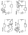
- the vessel 6 is inserted between split condenser halves 2a and 2b in Figs. 9 and 11, or between split evaporator halves 5a and 5b in Figs. 10 and 12. It is preferable that the vessel 6 be disposed in the neighborhood of the compressor 1 or the expansion device 3 as shown in Figs. 8, 9 and 11, because the amount of the R13 refri g- erant retained in the vessel is inclined to increase owing to the relatively high pressure.
- Figs. 13 and 14 illustrate other embodiments of a system constructed according to the invention in which two valves 7a, 7b are connected in parallel with each other.
- the first valve 7a is closed in the ordinary freezing mode and opened in the rapid freezing mode, and vice versa for the second valve 7b.
- the valves 7a, 7b are operated so that all refrigerants from the compressor 1 flow into the vessel 6 in the rapid freezing mode.
- Figs. 15 through 22 show further embodiments of the invention in which a gas-liquid separator 9 is provided on the outlet side of the compressor 2 for separating the refrigerant mixture into gaseous and liquid components 10, 11 for respective circulation through the first and second expansion devices 3a, 3b.
- Figs. 15 and 16 correspond respectively to Figs. 2 and 4 except for the gas-liquid separator.
- a heat exchanger 30 is provided in the outlet pipe from the first expansion device 3a proximate the vessel 6. This results in increasing the consisten.cy of the R13 refrigerant retained in the upper portion of the vessel, because the cooling of the vessel enhances the fractionating of the refrigerant.
- an adiabatic enclosure 40 is provided surrounding both the vessel 6 and the heat exchanger 30 to minimize any heat loss therefrom, whereby the fractionating operation is further enhanced.
- the first expansion device 3a is arranged on the pipe 21 within the vessel 6.
- the first expansion device 3a and the heat exchanger 30 are arranged to cool the refrigerant in the filler 8 within the vessel 6, which further increases the consistency of the R13 refrigerant.
- the second valve 7b is disposed at the inlet side of the evaporator 5 and is closed when the system is idle to prevent the refrigerant in the condenser 2 and the vessel 6 from flowing into the evaporator 5. This stabilizes the operation of the system when restarting during the ordinary freezing mode by maintaining the high and low boiling point refrigerants separated, and prevents the overloading of the compressor.
Landscapes
- Engineering & Computer Science (AREA)
- Chemical & Material Sciences (AREA)
- Physics & Mathematics (AREA)
- Thermal Sciences (AREA)
- Mechanical Engineering (AREA)
- General Engineering & Computer Science (AREA)
- Chemical Kinetics & Catalysis (AREA)
- Combustion & Propulsion (AREA)
- Materials Engineering (AREA)
- Organic Chemistry (AREA)
- Compression-Type Refrigeration Machines With Reversible Cycles (AREA)
- Devices That Are Associated With Refrigeration Equipment (AREA)
Applications Claiming Priority (6)
| Application Number | Priority Date | Filing Date | Title |
|---|---|---|---|
| JP7095383A JPS59197761A (ja) | 1983-04-22 | 1983-04-22 | 冷凍サイクル |
| JP70955/83 | 1983-04-22 | ||
| JP7095483A JPS59197762A (ja) | 1983-04-22 | 1983-04-22 | 冷凍サイクル |
| JP7095583A JPS59197763A (ja) | 1983-04-22 | 1983-04-22 | 冷凍サイクル |
| JP70953/83 | 1983-04-22 | ||
| JP70954/83 | 1983-04-22 |
Publications (3)
| Publication Number | Publication Date |
|---|---|
| EP0126237A2 true EP0126237A2 (de) | 1984-11-28 |
| EP0126237A3 EP0126237A3 (en) | 1985-05-15 |
| EP0126237B1 EP0126237B1 (de) | 1989-02-01 |
Family
ID=27300482
Family Applications (1)
| Application Number | Title | Priority Date | Filing Date |
|---|---|---|---|
| EP84103176A Expired EP0126237B1 (de) | 1983-04-22 | 1984-03-22 | Kältekreislaufsysteme und Kältemaschinen |
Country Status (6)
| Country | Link |
|---|---|
| US (2) | US4580415A (de) |
| EP (1) | EP0126237B1 (de) |
| AU (1) | AU559872B2 (de) |
| DE (1) | DE3476578D1 (de) |
| ES (1) | ES531797A0 (de) |
| HK (1) | HK54390A (de) |
Cited By (11)
| Publication number | Priority date | Publication date | Assignee | Title |
|---|---|---|---|---|
| EP0196051A3 (en) * | 1985-03-25 | 1988-05-25 | Matsushita Electric Industrial Co., Ltd. | Heat pump with a reservoir storing higher pressure refrigerant of non-azeotropic mixture |
| WO1993011201A1 (en) * | 1991-12-03 | 1993-06-10 | United States Environmental Protection Agency | Refrigerant compositions and processes for using same |
| EP0546447A1 (de) * | 1991-12-06 | 1993-06-16 | Peter Kaminsky | Verbesserungen in Kühlkreisläufen |
| WO1994007095A1 (de) * | 1992-09-15 | 1994-03-31 | Fritz Egger Gmbh | Verfahren und einrichtung zur leistungsregelung einer kompressions-wärmepumpe und/oder kältemaschine |
| EP1923645A4 (de) * | 2005-09-08 | 2009-02-18 | Dairei Co Ltd | Steuervorrichtung für eine ein nicht azeotropes kältemittel einsetzende kältemaschine |
| EP1876402A3 (de) * | 2006-07-05 | 2009-02-18 | Markus Kroll | Wärmepumpe mit einer Temperiereinrichtung |
| WO2009147172A1 (en) * | 2008-06-05 | 2009-12-10 | Alstom Technology Ltd. | Multi-refrigerant cooling system with provisions for adjustment of refrigerant composition |
| US20130213066A1 (en) * | 2012-02-21 | 2013-08-22 | Whirlpool Corporation | Refrigeration arrangement and methods for reducing charge migration |
| WO2012126702A3 (de) * | 2011-03-18 | 2013-08-22 | BSH Bosch und Siemens Hausgeräte GmbH | Kältegerät mit flüssigkeitsabscheider |
| US20130213065A1 (en) * | 2012-02-21 | 2013-08-22 | Whirlpool Corporation | Dual capillary tube / heat exchanger in combination with cycle priming for reducing charge migration |
| US9285161B2 (en) | 2012-02-21 | 2016-03-15 | Whirlpool Corporation | Refrigerator with variable capacity compressor and cycle priming action through capacity control and associated methods |
Families Citing this family (15)
| Publication number | Priority date | Publication date | Assignee | Title |
|---|---|---|---|---|
| KR930000852B1 (ko) * | 1987-07-31 | 1993-02-06 | 마쓰시다덴기산교 가부시기가이샤 | 히이트 펌프장치 |
| US4913714A (en) * | 1987-08-03 | 1990-04-03 | Nippondenso Co., Ltd. | Automotive air conditioner |
| RO105625B1 (ro) * | 1988-01-22 | 1992-10-30 | Proizv Ob Vypusku Bytovykh Kho | Agregat frigorific pentru instalatii frigorifice cu doua camere |
| JPH01273959A (ja) * | 1988-04-25 | 1989-11-01 | Nippon Denso Co Ltd | 車両用空気調和機 |
| US4972676A (en) * | 1988-12-23 | 1990-11-27 | Kabushiki Kaisha Toshiba | Refrigeration cycle apparatus having refrigerant separating system with pressure swing adsorption |
| US5012651A (en) * | 1988-12-28 | 1991-05-07 | Matsushita Electric Industrial Co., Ltd. | Heat pump apparatus |
| US5056329A (en) * | 1990-06-25 | 1991-10-15 | Battelle Memorial Institute | Heat pump systems |
| CN1079528C (zh) * | 1993-10-28 | 2002-02-20 | 株式会社日立制作所 | 制冷循环及其控制方法 |
| US5551255A (en) * | 1994-09-27 | 1996-09-03 | The United States Of America As Represented By The Secretary Of Commerce | Accumulator distillation insert for zeotropic refrigerant mixtures |
| JPH10267436A (ja) * | 1997-01-21 | 1998-10-09 | Mitsubishi Electric Corp | 冷凍空調装置 |
| JP4078812B2 (ja) * | 2000-04-26 | 2008-04-23 | 株式会社デンソー | 冷凍サイクル装置 |
| JP3941555B2 (ja) * | 2002-03-22 | 2007-07-04 | 株式会社デンソー | 冷凍サイクル装置および凝縮器 |
| DE06736535T1 (de) * | 2005-02-28 | 2008-06-05 | Honeywell International Inc. | Verbessertes verfahren zum mischen von kühlmitteln |
| JP4899489B2 (ja) * | 2006-01-19 | 2012-03-21 | ダイキン工業株式会社 | 冷凍装置 |
| CN109140811A (zh) * | 2018-10-11 | 2019-01-04 | 武汉巨力鼎兴冷链股份有限公司 | 一种具有高、低温冷藏切换功能的冷库循环系统 |
Family Cites Families (16)
| Publication number | Priority date | Publication date | Assignee | Title |
|---|---|---|---|---|
| US1866526A (en) * | 1928-02-07 | 1932-07-12 | Chicago Pneumatic Tool Co | Refrigerating apparatus |
| CH285802A (fr) * | 1950-03-28 | 1952-09-30 | Paillard Sa | Appareil de prise de vues à tourelle porte-objectifs. |
| US2841965A (en) * | 1954-06-29 | 1958-07-08 | Gen Electric | Dual capacity refrigeration |
| US2794328A (en) * | 1954-06-29 | 1957-06-04 | Gen Electric | Variable temperature refrigeration |
| NL207969A (de) * | 1955-06-28 | |||
| US2867094A (en) * | 1954-09-30 | 1959-01-06 | Gen Electric | Variable temperature refrigeration |
| US2938362A (en) * | 1955-09-02 | 1960-05-31 | Borg Warner | Multiple fluid refrigerating system |
| US2951349A (en) * | 1958-06-23 | 1960-09-06 | Gen Electric | Variable capacity refrigeration system |
| US2951350A (en) * | 1958-06-23 | 1960-09-06 | Gen Electric | Variable capacity refrigeration |
| DE1241468B (de) * | 1962-12-01 | 1967-06-01 | Andrija Fuderer Dr Ing | Kompressionsverfahren zur Kaelterzeugung |
| US3487653A (en) * | 1968-01-26 | 1970-01-06 | Associated Testing Lab Inc | Low temperature environmental test system |
| DE2203728A1 (de) * | 1971-03-23 | 1972-09-28 | VEB Monsator Haushaltgroßgerätekombinat Schwarzenberg Betrieb DKK Scharfenstein, χ 9366 Scharfenstein | Kühlmöbel mit Kühlfächern unterschiedlicher Temperatur, insbesondere Zweitemperatur-Haushaltkühlschrank |
| FR2400173A1 (fr) * | 1977-08-12 | 1979-03-09 | Electricite De France | Perfectionnements aux pompes a chaleur |
| JPS57198968A (en) * | 1981-05-29 | 1982-12-06 | Hitachi Ltd | Heat pump type refrigerator |
| US4406134A (en) * | 1981-11-23 | 1983-09-27 | General Electric Company | Two capillary vapor compression cycle device |
| US4393661A (en) * | 1981-12-10 | 1983-07-19 | General Electric Company | Means and method for regulating flowrate in a vapor compression cycle device |
-
1984
- 1984-03-09 US US06/588,011 patent/US4580415A/en not_active Expired - Lifetime
- 1984-03-22 DE DE8484103176T patent/DE3476578D1/de not_active Expired
- 1984-03-22 EP EP84103176A patent/EP0126237B1/de not_active Expired
- 1984-04-18 ES ES531797A patent/ES531797A0/es active Granted
- 1984-04-19 AU AU27164/84A patent/AU559872B2/en not_active Expired
-
1986
- 1986-01-30 US US06/824,322 patent/US4624114A/en not_active Expired - Lifetime
-
1990
- 1990-07-19 HK HK543/90A patent/HK54390A/xx unknown
Cited By (16)
| Publication number | Priority date | Publication date | Assignee | Title |
|---|---|---|---|---|
| EP0196051A3 (en) * | 1985-03-25 | 1988-05-25 | Matsushita Electric Industrial Co., Ltd. | Heat pump with a reservoir storing higher pressure refrigerant of non-azeotropic mixture |
| WO1993011201A1 (en) * | 1991-12-03 | 1993-06-10 | United States Environmental Protection Agency | Refrigerant compositions and processes for using same |
| US5650089A (en) * | 1991-12-03 | 1997-07-22 | The United States Of America, As Represented By The Administrator Of The U.S. Environmental Protection Agency | Refrigerant compositions with fluorinated dimethyl ether and either difluoroethane or cyclopropane, and use thereof |
| US6063305A (en) * | 1991-12-03 | 2000-05-16 | The United States Of America As Represented By The Administrator Of The Environmental Protection Agency | Refrigerant compositions containing a hydrofluoropropane and a hydrofluorocarbon |
| EP0546447A1 (de) * | 1991-12-06 | 1993-06-16 | Peter Kaminsky | Verbesserungen in Kühlkreisläufen |
| WO1994007095A1 (de) * | 1992-09-15 | 1994-03-31 | Fritz Egger Gmbh | Verfahren und einrichtung zur leistungsregelung einer kompressions-wärmepumpe und/oder kältemaschine |
| EP1923645A4 (de) * | 2005-09-08 | 2009-02-18 | Dairei Co Ltd | Steuervorrichtung für eine ein nicht azeotropes kältemittel einsetzende kältemaschine |
| EP1876402A3 (de) * | 2006-07-05 | 2009-02-18 | Markus Kroll | Wärmepumpe mit einer Temperiereinrichtung |
| WO2009147172A1 (en) * | 2008-06-05 | 2009-12-10 | Alstom Technology Ltd. | Multi-refrigerant cooling system with provisions for adjustment of refrigerant composition |
| WO2012126702A3 (de) * | 2011-03-18 | 2013-08-22 | BSH Bosch und Siemens Hausgeräte GmbH | Kältegerät mit flüssigkeitsabscheider |
| US20130213066A1 (en) * | 2012-02-21 | 2013-08-22 | Whirlpool Corporation | Refrigeration arrangement and methods for reducing charge migration |
| US20130213065A1 (en) * | 2012-02-21 | 2013-08-22 | Whirlpool Corporation | Dual capillary tube / heat exchanger in combination with cycle priming for reducing charge migration |
| EP2631568A3 (de) * | 2012-02-21 | 2014-08-13 | Whirlpool Corporation | Kühlschrankanordnung und Verfahren zur Reduzierung der Füllungsverlagerungsverluste |
| US9285161B2 (en) | 2012-02-21 | 2016-03-15 | Whirlpool Corporation | Refrigerator with variable capacity compressor and cycle priming action through capacity control and associated methods |
| US9618246B2 (en) | 2012-02-21 | 2017-04-11 | Whirlpool Corporation | Refrigeration arrangement and methods for reducing charge migration |
| US9696077B2 (en) | 2012-02-21 | 2017-07-04 | Whirlpool Corporation | Dual capillary tube / heat exchanger in combination with cycle priming for reducing charge migration |
Also Published As
| Publication number | Publication date |
|---|---|
| DE3476578D1 (en) | 1989-03-09 |
| ES8503824A1 (es) | 1985-03-01 |
| AU559872B2 (en) | 1987-03-19 |
| HK54390A (en) | 1990-07-27 |
| EP0126237B1 (de) | 1989-02-01 |
| EP0126237A3 (en) | 1985-05-15 |
| US4580415A (en) | 1986-04-08 |
| ES531797A0 (es) | 1985-03-01 |
| US4624114A (en) | 1986-11-25 |
| AU2716484A (en) | 1984-10-25 |
Similar Documents
| Publication | Publication Date | Title |
|---|---|---|
| EP0126237A2 (de) | Kältekreislaufsysteme und Kältemaschinen | |
| KR100339128B1 (ko) | 냉동장치, 냉동기, 냉동장치용 공냉식 응축기 유닛 및압축기 유닛 | |
| CA2080220A1 (en) | Household refrigerator with improved refrigeration circuit | |
| EP0541324A1 (de) | Kälteanlagen | |
| KR101092692B1 (ko) | 이코노마이저 및 이를 구비하는 다단 압축식 냉동기 | |
| JP3155653B2 (ja) | 混合冷媒を用いた冷凍装置 | |
| JP3756711B2 (ja) | 極低温冷凍装置 | |
| Little et al. | Low cost cryocoolers for cryoelectronics | |
| JPS59197763A (ja) | 冷凍サイクル | |
| JPH0138227B2 (de) | ||
| JP3596825B2 (ja) | 極低温冷凍機の低圧制御装置 | |
| JPH0468547B2 (de) | ||
| Luo et al. | Experimental comparison of mixed-refrigerant Joule-Thomson cryocoolers with two types of counterflow heat exchangers | |
| JPS59197761A (ja) | 冷凍サイクル | |
| JPH01273961A (ja) | 冷凍サイクル装置 | |
| JPS58195752A (ja) | 冷凍サイクル | |
| JPH10220915A (ja) | 冷凍装置 | |
| JPH01273962A (ja) | 冷凍装置 | |
| JPH01200156A (ja) | 冷凍サイクル装置 | |
| JPS63290358A (ja) | 冷凍サイクル装置 | |
| JPH03158659A (ja) | 冷凍装置 | |
| JPS63315868A (ja) | 極低温冷凍装置 | |
| JPS58140569A (ja) | 低温装置 | |
| KR19980023800A (ko) | 냉매관 분리장치 | |
| JPH05164409A (ja) | 冷凍装置 |
Legal Events
| Date | Code | Title | Description |
|---|---|---|---|
| PUAI | Public reference made under article 153(3) epc to a published international application that has entered the european phase |
Free format text: ORIGINAL CODE: 0009012 |
|
| AK | Designated contracting states |
Designated state(s): DE FR GB IT |
|
| PUAL | Search report despatched |
Free format text: ORIGINAL CODE: 0009013 |
|
| AK | Designated contracting states |
Designated state(s): DE FR GB IT |
|
| 17P | Request for examination filed |
Effective date: 19850913 |
|
| 17Q | First examination report despatched |
Effective date: 19860401 |
|
| D17Q | First examination report despatched (deleted) | ||
| GRAA | (expected) grant |
Free format text: ORIGINAL CODE: 0009210 |
|
| AK | Designated contracting states |
Kind code of ref document: B1 Designated state(s): DE FR GB IT |
|
| ITF | It: translation for a ep patent filed | ||
| REF | Corresponds to: |
Ref document number: 3476578 Country of ref document: DE Date of ref document: 19890309 |
|
| ET | Fr: translation filed | ||
| PLBE | No opposition filed within time limit |
Free format text: ORIGINAL CODE: 0009261 |
|
| STAA | Information on the status of an ep patent application or granted ep patent |
Free format text: STATUS: NO OPPOSITION FILED WITHIN TIME LIMIT |
|
| 26N | No opposition filed | ||
| ITTA | It: last paid annual fee | ||
| PGFP | Annual fee paid to national office [announced via postgrant information from national office to epo] |
Ref country code: FR Payment date: 19940310 Year of fee payment: 11 |
|
| PGFP | Annual fee paid to national office [announced via postgrant information from national office to epo] |
Ref country code: GB Payment date: 19940314 Year of fee payment: 11 |
|
| PGFP | Annual fee paid to national office [announced via postgrant information from national office to epo] |
Ref country code: DE Payment date: 19940323 Year of fee payment: 11 |
|
| PG25 | Lapsed in a contracting state [announced via postgrant information from national office to epo] |
Ref country code: GB Effective date: 19950322 |
|
| GBPC | Gb: european patent ceased through non-payment of renewal fee |
Effective date: 19950322 |
|
| PG25 | Lapsed in a contracting state [announced via postgrant information from national office to epo] |
Ref country code: FR Free format text: LAPSE BECAUSE OF NON-PAYMENT OF DUE FEES Effective date: 19951130 |
|
| PG25 | Lapsed in a contracting state [announced via postgrant information from national office to epo] |
Ref country code: DE Effective date: 19951201 |
|
| REG | Reference to a national code |
Ref country code: FR Ref legal event code: ST |