EP0126251A1 - Kamerazwischenstück das photographieren von Diapositiven in einem Diaprojektor ermöglicht - Google Patents
Kamerazwischenstück das photographieren von Diapositiven in einem Diaprojektor ermöglicht Download PDFInfo
- Publication number
- EP0126251A1 EP0126251A1 EP84103734A EP84103734A EP0126251A1 EP 0126251 A1 EP0126251 A1 EP 0126251A1 EP 84103734 A EP84103734 A EP 84103734A EP 84103734 A EP84103734 A EP 84103734A EP 0126251 A1 EP0126251 A1 EP 0126251A1
- Authority
- EP
- European Patent Office
- Prior art keywords
- lens
- projector
- attachment
- tubular member
- camera
- Prior art date
- Legal status (The legal status is an assumption and is not a legal conclusion. Google has not performed a legal analysis and makes no representation as to the accuracy of the status listed.)
- Granted
Links
- 230000007935 neutral effect Effects 0.000 claims abstract description 12
- 230000011514 reflex Effects 0.000 claims abstract description 9
- 102000001690 Factor VIII Human genes 0.000 description 4
- 108010054218 Factor VIII Proteins 0.000 description 4
- 238000006243 chemical reaction Methods 0.000 description 1
- 239000011521 glass Substances 0.000 description 1
- WFKWXMTUELFFGS-UHFFFAOYSA-N tungsten Chemical compound [W] WFKWXMTUELFFGS-UHFFFAOYSA-N 0.000 description 1
- 229910052721 tungsten Inorganic materials 0.000 description 1
- 239000010937 tungsten Substances 0.000 description 1
Images
Classifications
-
- G—PHYSICS
- G03—PHOTOGRAPHY; CINEMATOGRAPHY; ANALOGOUS TECHNIQUES USING WAVES OTHER THAN OPTICAL WAVES; ELECTROGRAPHY; HOLOGRAPHY
- G03B—APPARATUS OR ARRANGEMENTS FOR TAKING PHOTOGRAPHS OR FOR PROJECTING OR VIEWING THEM; APPARATUS OR ARRANGEMENTS EMPLOYING ANALOGOUS TECHNIQUES USING WAVES OTHER THAN OPTICAL WAVES; ACCESSORIES THEREFOR
- G03B27/00—Photographic printing apparatus
- G03B27/32—Projection printing apparatus, e.g. enlarger, copying camera
- G03B27/52—Details
- G03B27/62—Holders for the original
- G03B27/6207—Holders for the original in copying cameras
-
- G—PHYSICS
- G03—PHOTOGRAPHY; CINEMATOGRAPHY; ANALOGOUS TECHNIQUES USING WAVES OTHER THAN OPTICAL WAVES; ELECTROGRAPHY; HOLOGRAPHY
- G03B—APPARATUS OR ARRANGEMENTS FOR TAKING PHOTOGRAPHS OR FOR PROJECTING OR VIEWING THEM; APPARATUS OR ARRANGEMENTS EMPLOYING ANALOGOUS TECHNIQUES USING WAVES OTHER THAN OPTICAL WAVES; ACCESSORIES THEREFOR
- G03B27/00—Photographic printing apparatus
- G03B27/32—Projection printing apparatus, e.g. enlarger, copying camera
- G03B27/323—Copying cameras
Definitions
- the present invention relates to a camera attachment for photographing color transparencies in a slide projector.
- Patent 3,697,175 - Sullivan and 4,353,640 - Wyller are examples of the latter type accessories.
- the Sullivan patent shows a slide holder, an electronic flash unit and a light reflecting chamber for back lighting the slide and projecting the image thereon through a lens into the lens of the camera.
- the Wyller patent discloses a housing which includes a screen and film pack in the film plane, a shutter assembly and a light-tight connector for attaching the housing to the lens assembly of a conventional slide projector. The image on the slide is projected through the lens assembly into the housing and onto the film pack.
- the prior art devices are expensive and complex in that they provide special purpose attachments which duplicate the function of cameras and/or projectors already available. Either a special purpose accessory is provided to record an image from a conventional slide projector or another special purpose accessory is provided to project an image from a slide into a conventional camera.
- an elongated tubular connector one end of which is adapted to be attached to the lens mounting boss on the front of a single lens reflex camera, and the other end of which is adapted to be received within the lens receptacle of a projector, and a lens assembly in the connector intermediate the two ends for focusing an image from the projector onto the film plane of the camera.
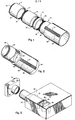
- the lens assembly 13 is then connected to the opposite end of the lens tube 11.
- the mounting boss 17 on the inner end of the lens assembly 13 is engaged within the mounting boss 15.
- the lens assembly is provided with an opening at its outer end which is internally threaded as at 18 to receive filters, etc.
- a factor 8 neutral density filter 37 is fitted to the macro lens by means of external threads 38 received within internal threads 18.
- the tubular member 12 is formed of two hollow tubes 19 and 20 interconnected to permit relative rotational movement between them.
- the free end of tube 19 is externally threaded as at 21 and is adapted to be connected to the factor 8 neutral density filter 37 by threads 21 engaged within internal threads 39 of the filter.
- Tube 20 is provided with an elongated spline 22 which extends axially of the tube and protrudes radially beyond the exterior surface of the tube.
- a plurality of generally parallel grooves 23 are formed in the surface of the elongated spline 22 and extend approximately normal to the axis of the tube.
- the tube 20 is dimensioned to be essentially the same exterior size and shape as the projector lens assembly of a conventional slide projector.
- the tube 20 is adapted to be received within the lens assembly receptacle of a projector with the spline 22 riding in a matching groove or keyway in the wall of the receptacle and with the grooves 23 meshed with the toothed wheel or gear which is used to adjust the position of the lens assembly within the receptacle.
- FIG. 2 the lens tube, lens assembly, factor 8 neutral density filter and tubular member of FIG. 1 are combined into a unitary structure.
- the attachment of FIG. 2 includes a tubular section 24 which has a mounting boss at one end as at 25 and is adapted to be received by the lens mounting boss at the opening of a camera.
- the opposite end of section 24 is joined to a tubular member 26 so as to permit relative rotational movement therebetween.
- Tubular member 26 is similar to tube 20 of FIG. 1 and is provided with an elongated spline 27 and a series of grooves 28.
- a 50 mm macro lens 29 is mounted within the tubular section 24 adjacent to the interconnection with tubular member 26.
- a factor 8 neutral density filter 40 is mounted on the end of the tubular section 26.
- section 24 The interior of section 24 is blocked with an annular support 30 which surrounds and secures the lens 29.
- the tubular section 24 serves as a lens tube to position the macro lens such that a 1:1 image size ratio is obtained.
- Tubular member 26 is adapted to be received within the lens assembly receptacle of a slide projector.
- FIG. 3 illustrates how the attachment of the present invention connects a single lens reflex 35 mm camera 31 to a slide projector 32 in position to photograph the individual slides at the slide station 33 within the projector.
- the lens assembly of the camera and the projector lens assembly are both removed, then the lens mounting boss 25 of section 24 is engaged within the mounting boss of the lens assembly opening in the front of the camera.
- the tubular member 26 is positioned within the lens assembly receptacle of the projector with the grooves 28 in engagement with a gear in the interior of the projector which is rotated by the knob 34 protruding from the projector.
- Tubular member 26 thus supports the camera in position adjacent the projector.
- the interconnection between section 24 and tubular member 26 allows the camera to be rotated relative to the projector to align the film with the slides.
- a light-diffusing screen 35 made of translucent, but non-transparent, glass or plastic is positioned between the slide station 33 and the projector light source 36.
- the camera With the camera in the position shown and with a color transparency in the slide station 33, the camera can be focused by looking through the eyepiece of the camera view finder. Rotation of the knob 34 will move tubular member 26 axially within the projector lens assembly receptacle and adjust the position of the macro lens 29 relative to the slide station to focus the image of the transparency onto the film plane of the camera. Since the light passing through the transparency is very bright, even though diffused, it is necessary to have the neutral density filter in the system and it may be desirable to place a filter over the eyepiece of the view finder in order to see the image clearly for focusing. With the neutral density filter the built in light meter of the camera will function in its effective range and focusing can be accomplished through the eye piece with the naked eye.
- the screen 35 diffuses the light to allow the image to be viewed for focusing and also prevents photographing of the light source through the transparency. It is desirable to use tungsten film, such as Ectachrome ASA 160, or a filter for accurate photographing of the image.
- the slides to be photographed should be aligned with the largest dimension of the transparency parallel to the direction of film movement within the camera. If a carousel type projector is being used, the carousel is mounted on the projector, the camera set on automatic and then shot in rapid succession after advancing each slide to the slide station in turn.
- a standard slide projector i.e., one that does not have the automatic focus feature
- the present attachment has been described in connection with a 35 mm camera, but it is useable with any single lens reflex camera which has a removable lens assembly.
- FIG. 1 functions the same as that of FIG. 2 to position the camera on the projector. However, the image can be brought into proper focus by means of the focusing knob on the projector and/or the focusing adjustment on the lens assembly.
Landscapes
- Physics & Mathematics (AREA)
- General Physics & Mathematics (AREA)
- Accessories Of Cameras (AREA)
- Cameras Adapted For Combination With Other Photographic Or Optical Apparatuses (AREA)
- Projection Apparatus (AREA)
- Overhead Projectors And Projection Screens (AREA)
Priority Applications (1)
| Application Number | Priority Date | Filing Date | Title |
|---|---|---|---|
| AT84103734T ATE37241T1 (de) | 1983-04-12 | 1984-04-04 | Kamerazwischenstueck das photographieren von diapositiven in einem diaprojektor ermoeglicht. |
Applications Claiming Priority (2)
| Application Number | Priority Date | Filing Date | Title |
|---|---|---|---|
| US48427883A | 1983-04-12 | 1983-04-12 | |
| US484278 | 1983-04-12 |
Publications (2)
| Publication Number | Publication Date |
|---|---|
| EP0126251A1 true EP0126251A1 (de) | 1984-11-28 |
| EP0126251B1 EP0126251B1 (de) | 1988-09-14 |
Family
ID=23923483
Family Applications (1)
| Application Number | Title | Priority Date | Filing Date |
|---|---|---|---|
| EP84103734A Expired EP0126251B1 (de) | 1983-04-12 | 1984-04-04 | Kamerazwischenstück das photographieren von Diapositiven in einem Diaprojektor ermöglicht |
Country Status (5)
| Country | Link |
|---|---|
| EP (1) | EP0126251B1 (de) |
| JP (2) | JPS59191027A (de) |
| AT (1) | ATE37241T1 (de) |
| CA (1) | CA1222159A (de) |
| DE (1) | DE3474073D1 (de) |
Citations (5)
| Publication number | Priority date | Publication date | Assignee | Title |
|---|---|---|---|---|
| US3689148A (en) * | 1970-08-27 | 1972-09-05 | Robert B Black | Transparency copying attachment |
| DE2703494A1 (de) * | 1977-01-28 | 1978-08-03 | Europatent Sa | Vorrichtung zum befestigen einer fuellung in einem traegermaterial |
| DE2730494A1 (de) * | 1977-07-06 | 1979-01-25 | Bockeloh Geb Becker Brigitte | Vorrichtung zur herstellung von kopien von diapositiven |
| US4194834A (en) * | 1975-12-02 | 1980-03-25 | Zelacolor Systems Establishment | Unit for reproducing transparent originals, or the like |
| US4353640A (en) * | 1979-01-18 | 1982-10-12 | Wyller Arne A | Print maker |
Family Cites Families (2)
| Publication number | Priority date | Publication date | Assignee | Title |
|---|---|---|---|---|
| JPS4925502A (de) * | 1972-07-05 | 1974-03-07 | ||
| JPS5341024B2 (de) * | 1973-07-20 | 1978-10-31 |
-
1984
- 1984-03-20 CA CA000449981A patent/CA1222159A/en not_active Expired
- 1984-04-03 JP JP59065291A patent/JPS59191027A/ja active Pending
- 1984-04-04 EP EP84103734A patent/EP0126251B1/de not_active Expired
- 1984-04-04 DE DE8484103734T patent/DE3474073D1/de not_active Expired
- 1984-04-04 AT AT84103734T patent/ATE37241T1/de not_active IP Right Cessation
-
1992
- 1992-02-24 JP JP1992020997U patent/JPH0723782Y2/ja not_active Expired - Lifetime
Patent Citations (5)
| Publication number | Priority date | Publication date | Assignee | Title |
|---|---|---|---|---|
| US3689148A (en) * | 1970-08-27 | 1972-09-05 | Robert B Black | Transparency copying attachment |
| US4194834A (en) * | 1975-12-02 | 1980-03-25 | Zelacolor Systems Establishment | Unit for reproducing transparent originals, or the like |
| DE2703494A1 (de) * | 1977-01-28 | 1978-08-03 | Europatent Sa | Vorrichtung zum befestigen einer fuellung in einem traegermaterial |
| DE2730494A1 (de) * | 1977-07-06 | 1979-01-25 | Bockeloh Geb Becker Brigitte | Vorrichtung zur herstellung von kopien von diapositiven |
| US4353640A (en) * | 1979-01-18 | 1982-10-12 | Wyller Arne A | Print maker |
Also Published As
| Publication number | Publication date |
|---|---|
| ATE37241T1 (de) | 1988-09-15 |
| CA1222159A (en) | 1987-05-26 |
| JPS59191027A (ja) | 1984-10-30 |
| DE3474073D1 (en) | 1988-10-20 |
| JPH0723782Y2 (ja) | 1995-05-31 |
| JPH0687954U (ja) | 1994-12-22 |
| EP0126251B1 (de) | 1988-09-14 |
Similar Documents
| Publication | Publication Date | Title |
|---|---|---|
| US4914461A (en) | Camera having variable illumination angle strobe device and zoom lens | |
| US3836927A (en) | Close-up flash camera attachment | |
| US6052534A (en) | Close-up photographing apparatus | |
| US4786926A (en) | Camera attachment for enabling photographing of transparencies in a slide projector | |
| US5486885A (en) | Character image display apparatus for a camera | |
| US4862199A (en) | Adjustable adapter for borescope and film/video camera | |
| US3574954A (en) | Optical educational toy | |
| US3689148A (en) | Transparency copying attachment | |
| US3330193A (en) | Camera apparatus | |
| US3386360A (en) | Flash filter | |
| US3583300A (en) | Photographic camera with viewfinder | |
| US4239376A (en) | Print maker | |
| EP0126251B1 (de) | Kamerazwischenstück das photographieren von Diapositiven in einem Diaprojektor ermöglicht | |
| US3774992A (en) | Optical framing device for photographic cameras | |
| US3680459A (en) | Camera objective adjustable for flash and non-flash photography | |
| US3388645A (en) | Photographic device | |
| JP3623565B2 (ja) | 近接撮影用アダプタ | |
| JP3471116B2 (ja) | レンズ付きフイルムユニット用プレ露光装置 | |
| JPS5932776B2 (ja) | 写真装置 | |
| US3765313A (en) | View finder | |
| JP2604851Y2 (ja) | ステレオ写真撮影装置 | |
| JP2002182289A (ja) | カメラ | |
| US3286609A (en) | Light receiving device for electrical exposure meter for cameras | |
| US3699867A (en) | Distance establishing arrangement for photographic camera | |
| JP3987966B2 (ja) | カメラのファインダー構造 |
Legal Events
| Date | Code | Title | Description |
|---|---|---|---|
| PUAI | Public reference made under article 153(3) epc to a published international application that has entered the european phase |
Free format text: ORIGINAL CODE: 0009012 |
|
| AK | Designated contracting states |
Designated state(s): AT BE CH DE FR GB IT LI NL SE |
|
| 17P | Request for examination filed |
Effective date: 19850528 |
|
| 17Q | First examination report despatched |
Effective date: 19860818 |
|
| D17Q | First examination report despatched (deleted) | ||
| GRAA | (expected) grant |
Free format text: ORIGINAL CODE: 0009210 |
|
| AK | Designated contracting states |
Kind code of ref document: B1 Designated state(s): AT BE CH DE FR GB IT LI NL SE |
|
| REF | Corresponds to: |
Ref document number: 37241 Country of ref document: AT Date of ref document: 19880915 Kind code of ref document: T |
|
| REF | Corresponds to: |
Ref document number: 3474073 Country of ref document: DE Date of ref document: 19881020 |
|
| ET | Fr: translation filed | ||
| ITF | It: translation for a ep patent filed | ||
| PLBE | No opposition filed within time limit |
Free format text: ORIGINAL CODE: 0009261 |
|
| STAA | Information on the status of an ep patent application or granted ep patent |
Free format text: STATUS: NO OPPOSITION FILED WITHIN TIME LIMIT |
|
| 26N | No opposition filed | ||
| ITTA | It: last paid annual fee | ||
| EAL | Se: european patent in force in sweden |
Ref document number: 84103734.4 |
|
| PGFP | Annual fee paid to national office [announced via postgrant information from national office to epo] |
Ref country code: GB Payment date: 19960404 Year of fee payment: 13 |
|
| PGFP | Annual fee paid to national office [announced via postgrant information from national office to epo] |
Ref country code: SE Payment date: 19960603 Year of fee payment: 13 |
|
| PGFP | Annual fee paid to national office [announced via postgrant information from national office to epo] |
Ref country code: FR Payment date: 19960604 Year of fee payment: 13 |
|
| PGFP | Annual fee paid to national office [announced via postgrant information from national office to epo] |
Ref country code: CH Payment date: 19960606 Year of fee payment: 13 |
|
| PGFP | Annual fee paid to national office [announced via postgrant information from national office to epo] |
Ref country code: AT Payment date: 19960612 Year of fee payment: 13 Ref country code: BE Payment date: 19960612 Year of fee payment: 13 |
|
| PGFP | Annual fee paid to national office [announced via postgrant information from national office to epo] |
Ref country code: NL Payment date: 19960618 Year of fee payment: 13 |
|
| PGFP | Annual fee paid to national office [announced via postgrant information from national office to epo] |
Ref country code: DE Payment date: 19960830 Year of fee payment: 13 |
|
| PG25 | Lapsed in a contracting state [announced via postgrant information from national office to epo] |
Ref country code: GB Effective date: 19970404 Ref country code: AT Effective date: 19970404 |
|
| PG25 | Lapsed in a contracting state [announced via postgrant information from national office to epo] |
Ref country code: SE Effective date: 19970405 |
|
| PG25 | Lapsed in a contracting state [announced via postgrant information from national office to epo] |
Ref country code: CH Free format text: LAPSE BECAUSE OF NON-PAYMENT OF DUE FEES Effective date: 19970430 Ref country code: BE Effective date: 19970430 Ref country code: LI Free format text: LAPSE BECAUSE OF NON-PAYMENT OF DUE FEES Effective date: 19970430 |
|
| BERE | Be: lapsed |
Owner name: HURVITZ JAMES S. Effective date: 19970430 |
|
| PG25 | Lapsed in a contracting state [announced via postgrant information from national office to epo] |
Ref country code: NL Effective date: 19971101 |
|
| GBPC | Gb: european patent ceased through non-payment of renewal fee |
Effective date: 19970404 |
|
| REG | Reference to a national code |
Ref country code: CH Ref legal event code: PL |
|
| PG25 | Lapsed in a contracting state [announced via postgrant information from national office to epo] |
Ref country code: FR Free format text: LAPSE BECAUSE OF NON-PAYMENT OF DUE FEES Effective date: 19971231 |
|
| PG25 | Lapsed in a contracting state [announced via postgrant information from national office to epo] |
Ref country code: DE Free format text: LAPSE BECAUSE OF NON-PAYMENT OF DUE FEES Effective date: 19980101 |
|
| NLV4 | Nl: lapsed or anulled due to non-payment of the annual fee |
Effective date: 19971101 |
|
| EUG | Se: european patent has lapsed |
Ref document number: 84103734.4 |
|
| REG | Reference to a national code |
Ref country code: FR Ref legal event code: ST |