EP0126257A1 - Dispositif pour limiter la vitesse d'un véhicule - Google Patents
Dispositif pour limiter la vitesse d'un véhicule Download PDFInfo
- Publication number
- EP0126257A1 EP0126257A1 EP84103887A EP84103887A EP0126257A1 EP 0126257 A1 EP0126257 A1 EP 0126257A1 EP 84103887 A EP84103887 A EP 84103887A EP 84103887 A EP84103887 A EP 84103887A EP 0126257 A1 EP0126257 A1 EP 0126257A1
- Authority
- EP
- European Patent Office
- Prior art keywords
- actuator
- speed
- engine
- normal
- normal position
- Prior art date
- Legal status (The legal status is an assumption and is not a legal conclusion. Google has not performed a legal analysis and makes no representation as to the accuracy of the status listed.)
- Granted
Links
Images

Classifications
-
- B—PERFORMING OPERATIONS; TRANSPORTING
- B60—VEHICLES IN GENERAL
- B60K—ARRANGEMENT OR MOUNTING OF PROPULSION UNITS OR OF TRANSMISSIONS IN VEHICLES; ARRANGEMENT OR MOUNTING OF PLURAL DIVERSE PRIME-MOVERS IN VEHICLES; AUXILIARY DRIVES FOR VEHICLES; INSTRUMENTATION OR DASHBOARDS FOR VEHICLES; ARRANGEMENTS IN CONNECTION WITH COOLING, AIR INTAKE, GAS EXHAUST OR FUEL SUPPLY OF PROPULSION UNITS IN VEHICLES
- B60K26/00—Arrangement or mounting of propulsion-unit control devices in vehicles
- B60K26/04—Arrangement or mounting of propulsion-unit control devices in vehicles of means connecting initiating means or elements to propulsion unit
-
- B—PERFORMING OPERATIONS; TRANSPORTING
- B60—VEHICLES IN GENERAL
- B60K—ARRANGEMENT OR MOUNTING OF PROPULSION UNITS OR OF TRANSMISSIONS IN VEHICLES; ARRANGEMENT OR MOUNTING OF PLURAL DIVERSE PRIME-MOVERS IN VEHICLES; AUXILIARY DRIVES FOR VEHICLES; INSTRUMENTATION OR DASHBOARDS FOR VEHICLES; ARRANGEMENTS IN CONNECTION WITH COOLING, AIR INTAKE, GAS EXHAUST OR FUEL SUPPLY OF PROPULSION UNITS IN VEHICLES
- B60K31/00—Vehicle fittings, acting on a single sub-unit only, for automatically controlling vehicle speed, i.e. preventing speed from exceeding an arbitrarily established velocity or maintaining speed at a particular velocity, as selected by the vehicle operator
- B60K31/02—Vehicle fittings, acting on a single sub-unit only, for automatically controlling vehicle speed, i.e. preventing speed from exceeding an arbitrarily established velocity or maintaining speed at a particular velocity, as selected by the vehicle operator including electrically actuated servomechanism
- B60K31/04—Vehicle fittings, acting on a single sub-unit only, for automatically controlling vehicle speed, i.e. preventing speed from exceeding an arbitrarily established velocity or maintaining speed at a particular velocity, as selected by the vehicle operator including electrically actuated servomechanism and means for comparing one electrical quantity, e.g. voltage, pulse, waveform, flux, or the like, with another quantity of a like kind, which comparison means is involved in the development of an electrical signal which is fed into the controlling means
- B60K31/042—Vehicle fittings, acting on a single sub-unit only, for automatically controlling vehicle speed, i.e. preventing speed from exceeding an arbitrarily established velocity or maintaining speed at a particular velocity, as selected by the vehicle operator including electrically actuated servomechanism and means for comparing one electrical quantity, e.g. voltage, pulse, waveform, flux, or the like, with another quantity of a like kind, which comparison means is involved in the development of an electrical signal which is fed into the controlling means where at least one electrical quantity is set by the vehicle operator
Definitions
- the invention relates to a device for limiting the driving speed or the engine speed of a motor vehicle, with a setpoint generator, a speed or speed actual value transmitter and a control unit processing the signals of the two transmitters, which forms a control signal from the signal difference, by the an actuator can be actuated, which is assigned to a transmission device that serves to transmit the movement of an accelerator pedal to the fuel metering device, wherein when a limit speed or limit speed set on the setpoint generator is exceeded, the actuator moves the effective length of the transmission device from a normal position towards a reduced position is changeably movable to reduce the amount of fuel.
- a pneumatic stop cylinder which is also arranged in the transmission device, is pressurized when the engine stops so that the effective length of the transmission device is changed in the direction of a reduction in the amount of fuel.
- This stop cylinder with its pressure supply and pressure control is both component and space-consuming, which is particularly disadvantageous in a motor vehicle that has only a small space.
- the object of the invention is therefore to provide a device according to the preamble which brings about a reduction in the amount of fuel when the engine is stopped with a few simple means.
- the actuator can be moved into the normal position when the engine is started and into the reduced position when the engine is not in operation and can be blocked outside the set limit speed in the normal position or reduced position assumed.
- an additional component such as a stop cylinder is no longer required, since in addition to its normal speed or speed limitation function, the actuator also takes over the fuel-reducing stop function when the engine is switched off. Since the fuel reduction of the stop function is so great that the diesel engine of a parked vehicle cannot self-ignite if it is parked on a slope, for example, and starts to roll independently, this also results in the third function, a roll lock. This third function too takes place without additional effort by the actuator, since this not only moves to the reduced position when the engine is stopped, but is also held there during the entire engine stop.
- Another advantage that results from the combination of the limiting function and the stop function performed by the actuator is that if the manipulation to switch off the limiter function, the stop function is switched off at the same time, so that the motor could no longer be switched off. The risk of an impermissible deactivation of the limiter function is thus considerably reduced.
- An electrical drive which can be controlled by a contact of the travel switch, is preferably used as the simple drive means for the actuator. As a result, no additional switches that the driver deliberately needs to operate are required, since the correct switching function is automatically carried out by actuating the ignition key.
- the actuator can either be non-positively by e.g. Spring loading or positively by e.g. a self-locking transmission between the drive motor and actuator can be blocked in the normal and / or reduced position. Blockability can be achieved with simple components of small size.
- a simple reduction in the effective length of the transmission device is achieved if a translation in the effective movement course of the transmission device can be changed by the actuator. Only a small amount of space is required if the transmission is a lever transmission, the joint of which is through the actuator is movable.
- the actuator can have a pivotable lever between the normal position and the reduced position in a simple manner. If the swivel lever can be acted upon by a snap spring in its normal position or reduction position, this simple and inexpensive component achieves lockability both in the normal and in the reduced position.
- the device shown in Figures 1-3 has an accelerator pedal 1 to which one end of a regulating rod 2 of a transmission device 3 is articulated approximately axially movable.
- the other end of the regulating rod 2 is articulated on an arm 6 of a two-armed lever 5 pivotable about an axis of rotation 4.
- On the other arm 7 of the lever 5 is articulated with its one end an axially movable to the regulating rod 2 limiter rod 8, the other end of which is pivotable about a fixed pivot point 9 pivot lever 10 of an actuator.
- the pivot lever 10 can be pivoted between a normal position (FIGS. 1 and 2) and a reduced position (FIG. 3) and is loaded by a snap spring 11 either in the normal position or in the reduced position.
- the snap spring 11 is a tension spring engaging at one end on the swivel lever, which is attached at its other end at a point on the normal to the longitudinal extension of the limiter rod intersecting the pivot point 9.
- An overtravel element 12 formed by a spring cylinder is arranged in the limiter rod 8.
- the axis of rotation 4 is not stationary, but is articulated on one end of an actuating lever 13.
- the other end of the actuating lever 13 is pivotable about the axis of a shaft 14 to which the actuating lever is rigidly connected.
- An injection pump lever (not shown) can be pivoted from the pivoting movement of the shaft 14.
- a throttle valve can also be pivoted from the shaft 14.
- the actuating lever Via a stop 15 of the actuating lever 13, against which the arm 7 can be placed in the full load direction when the lever 5 is actuated, the actuating lever can also be moved in the full load direction when the accelerator pedal 1 is moved in the full load direction.
- the pivot lever 10 By pivoting the pivot lever 10 from the normal position into the reduced position, the lever 5 and with it its axis of rotation 4 are moved to the right.
- the actuating lever 13 pivots to the right about the axis of the shaft 14 and takes the shaft 14 with it in a direction reducing the amount of fuel.
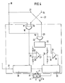
- the control of the movement of the pivot lever 10 can be seen from Figure 4.
- the pole 16 is connected to a voltage source, not shown.
- a connection leads from the pole 16 to an input 17 of a first AND gate 18, to an input 19 of a second AND gate 20, and to an OFF contact 21 of a travel switch 22.
- the travel switch 22 connects the OFF in its one switching position -Contact 21 with the second input 23 of the AND gate 20 and, in its other switching position, an ON contact 24 with the second input 25 of the AND gate 18.
- the output signal of the AND gate 18, which indicates that the vehicle engine is in operation, is fed to both a limiter unit 38 and the one input 26 of an amplifier 27.
- the second input 28 is connected to a voltage divider 29.
- the output signal of the amplifier 27 is fed to a driver stage 30 for the electromotive drive 31 of the swivel lever 10.
- the output of the AND gate 20 leads to a timing element 32 which, when actuated for a certain time (for example 10 seconds), supplies an output signal to an input 33 of an amplifier 34.
- the other input 35 of the amplifier 34 is connected to a voltage divider 36.
- the output of amplifier 34 leads to driver stage 30.
- the limiter unit 38 receives a speed or speed signal at an input 37.
- the travel switch -22 In the position shown, the travel switch -22 is in its OFF position. If it is switched to the ON position, the AND gate 18 receives a signal at its two inputs 17 and 25, so that it outputs an output signal both to the limiter unit 38 and via the amplifier 27 to the driver stage 30.
- the limiter unit 38 Since the speed or speed signal is below a setpoint set on a setpoint generator (not shown) of the limiter unit 38 and at the same time the limiter unit 38 receives an ON signal, it drives the driver stage 3D in the normal position, so that the pivot lever 10 is out of its solid line shown reduction position swings into its normal position drawn with a broken line and is held there by the snap spring 11.
- the latter controls the driver stage 30 in such a way that the pivot lever 10 is pivoted by a corresponding amount in the direction of the reduced position.
- the force of the snap spring 11 is overcome. If, after a driving operation, the travel switch 22 is switched from the ON position to the OFF position, the AND gate 18 no longer emits a signal to the limiter unit 38. This means that it is deactivated.
- the AND gate 20 now receives a signal at both inputs 19 and 23, so that the timing element 32 receives an input signal.
- the timer 32 sends a signal to the driver stage 30 via the amplifier 34, by means of which the driver stage 30 is driven into the reduced position and moves the swivel lever 10 into this position.
- the time period of the timing element 32 is dimensioned such that the pivot lever 10 moves safely into its reduced position. There it is then held by the snap spring 11.
- the voltage dividers 29 and 36 present at the second inputs 29 and 35 of the amplifiers 27 and 37 serve as fuse elements so that interference signals cannot trigger a control of the driver stage.
Landscapes
- Engineering & Computer Science (AREA)
- Chemical & Material Sciences (AREA)
- Combustion & Propulsion (AREA)
- Transportation (AREA)
- Mechanical Engineering (AREA)
- High-Pressure Fuel Injection Pump Control (AREA)
- Control Of Throttle Valves Provided In The Intake System Or In The Exhaust System (AREA)
Applications Claiming Priority (2)
| Application Number | Priority Date | Filing Date | Title |
|---|---|---|---|
| DE3318430 | 1983-05-20 | ||
| DE19833318430 DE3318430A1 (de) | 1983-05-20 | 1983-05-20 | Einrichtung zum begrenzen der fahrgeschwindigkeit |
Publications (2)
| Publication Number | Publication Date |
|---|---|
| EP0126257A1 true EP0126257A1 (fr) | 1984-11-28 |
| EP0126257B1 EP0126257B1 (fr) | 1986-06-18 |
Family
ID=6199508
Family Applications (1)
| Application Number | Title | Priority Date | Filing Date |
|---|---|---|---|
| EP84103887A Expired EP0126257B1 (fr) | 1983-05-20 | 1984-04-07 | Dispositif pour limiter la vitesse d'un véhicule |
Country Status (2)
| Country | Link |
|---|---|
| EP (1) | EP0126257B1 (fr) |
| DE (2) | DE3318430A1 (fr) |
Citations (5)
| Publication number | Priority date | Publication date | Assignee | Title |
|---|---|---|---|---|
| GB937629A (en) * | 1960-08-26 | 1963-09-25 | Daimler Benz Ag | Improvements relating to the automatic regulation of the speed of vehicles |
| US3708031A (en) * | 1970-12-31 | 1973-01-02 | Ford Motor Co | Maximum vehicle speed limiter |
| DE2200371A1 (de) * | 1972-01-05 | 1973-07-12 | Leonhard Holzberger | Geraet zum einbau in kraftfahrzeuge jeglicher art, zur zwanglaeufigen einhaltung der jeweiligen vorgeschriebenen geschwindigkeit |
| US4140202A (en) * | 1976-06-24 | 1979-02-20 | Associated Engineering Limited | Speed responsive systems |
| EP0043709A2 (fr) * | 1980-07-03 | 1982-01-13 | Kiloking (Proprietary) Limited | Un véhicule et un dispositif de commande du fonctionnement d'un véhicule |
-
1983
- 1983-05-20 DE DE19833318430 patent/DE3318430A1/de not_active Withdrawn
-
1984
- 1984-04-07 EP EP84103887A patent/EP0126257B1/fr not_active Expired
- 1984-04-07 DE DE8484103887T patent/DE3460242D1/de not_active Expired
Patent Citations (5)
| Publication number | Priority date | Publication date | Assignee | Title |
|---|---|---|---|---|
| GB937629A (en) * | 1960-08-26 | 1963-09-25 | Daimler Benz Ag | Improvements relating to the automatic regulation of the speed of vehicles |
| US3708031A (en) * | 1970-12-31 | 1973-01-02 | Ford Motor Co | Maximum vehicle speed limiter |
| DE2200371A1 (de) * | 1972-01-05 | 1973-07-12 | Leonhard Holzberger | Geraet zum einbau in kraftfahrzeuge jeglicher art, zur zwanglaeufigen einhaltung der jeweiligen vorgeschriebenen geschwindigkeit |
| US4140202A (en) * | 1976-06-24 | 1979-02-20 | Associated Engineering Limited | Speed responsive systems |
| EP0043709A2 (fr) * | 1980-07-03 | 1982-01-13 | Kiloking (Proprietary) Limited | Un véhicule et un dispositif de commande du fonctionnement d'un véhicule |
Also Published As
| Publication number | Publication date |
|---|---|
| EP0126257B1 (fr) | 1986-06-18 |
| DE3460242D1 (en) | 1986-07-24 |
| DE3318430A1 (de) | 1984-11-22 |
Similar Documents
| Publication | Publication Date | Title |
|---|---|---|
| EP0081630B1 (fr) | Pédale d'accélérateur électrique | |
| EP0960276B1 (fr) | Circuit pour un relais d'enclenchement | |
| EP0326553B1 (fr) | Systeme pour le dosage regule d'air de combustion dans un moteur a combustion interne | |
| DE3641244C3 (de) | Anordnung für ein Kraftfahrzeug | |
| EP0464041B1 (fr) | Procede pour determiner au moins une position terminale d'un dispositif d'ajustement dans un vehicule automobile | |
| DE4239687A1 (de) | Lineare Stellvorrichtung zur Betätigung einer Maschinensteuerung | |
| DE3109780A1 (de) | Steuergeraet, insbesondere schubbedarfs-steuergeraet fuer flugzeuge | |
| EP0072395A2 (fr) | Installation pour commander la position d'un élément influençant un mélange air-carburant | |
| DE2534565B2 (de) | Automatische elektrisch geteuerte Schaltvorricthung für ein Zahnradwechselgetriebe für Fahrzeuge | |
| DE2923276A1 (de) | Kraftstoffeinspritzvorrichtung | |
| WO1988001334A1 (fr) | Systeme de positionnement, notamment de verrouillage des portes de voitures | |
| EP0126257B1 (fr) | Dispositif pour limiter la vitesse d'un véhicule | |
| EP0250873B1 (fr) | Dispositif pour ajuster la vitesse de déplacement d'un véhicule automobile | |
| EP0260372B1 (fr) | Dispositif de limitation de la vitesse d'un véhicule automobile | |
| DE3907193C2 (de) | Fahrgeschwindigkeitsregler für ein Kraftfahrzeug | |
| DE1576305C3 (de) | Auf die Drosselklappe einer Brennkraftmaschine wirkender Geschwindigkeitsregler für Kraftfahrzeuge | |
| DE3809910A1 (de) | Vorrichtung zur leistungsbeeinflussung von brennkraftmaschinen | |
| EP0222126B1 (fr) | Actionneur électrique pour un dispositif de réglage de la vitesse d'un véhicule à moteur | |
| DE1214103B (de) | Einrichtung zum Regeln und Begrenzen der Fahrgeschwindigkeit von Kraftfahrzeugen | |
| DE2935321A1 (de) | Steuereinrichtung fuer die einspritzmenge einer einspritzpumpe bei einem dieselmotor | |
| DE3436245C2 (de) | Geschwindigkeitsbegrenzer für ein Kraftfahrzeug | |
| DE60008611T2 (de) | Anlasser für Kraftfahrzeuge mit geringerem Verschleiss | |
| DE3619642C2 (fr) | ||
| DE4213980A1 (de) | Hydraulische servolenkung mit geschwindigkeitsabhaengiger ventilkennlinie | |
| DE844863C (de) | Von der Fahrgeschwindigkeit und von der Energiezufuhr beeinflusste Getriebeschaltung fuer Kraftfahrzeuge |
Legal Events
| Date | Code | Title | Description |
|---|---|---|---|
| PUAI | Public reference made under article 153(3) epc to a published international application that has entered the european phase |
Free format text: ORIGINAL CODE: 0009012 |
|
| AK | Designated contracting states |
Designated state(s): DE FR GB IT SE |
|
| 17P | Request for examination filed |
Effective date: 19840928 |
|
| ITF | It: translation for a ep patent filed | ||
| GRAA | (expected) grant |
Free format text: ORIGINAL CODE: 0009210 |
|
| AK | Designated contracting states |
Kind code of ref document: B1 Designated state(s): DE FR GB IT SE |
|
| REF | Corresponds to: |
Ref document number: 3460242 Country of ref document: DE Date of ref document: 19860724 |
|
| ET | Fr: translation filed | ||
| PLBE | No opposition filed within time limit |
Free format text: ORIGINAL CODE: 0009261 |
|
| STAA | Information on the status of an ep patent application or granted ep patent |
Free format text: STATUS: NO OPPOSITION FILED WITHIN TIME LIMIT |
|
| 26N | No opposition filed | ||
| ITTA | It: last paid annual fee | ||
| PGFP | Annual fee paid to national office [announced via postgrant information from national office to epo] |
Ref country code: SE Payment date: 19940329 Year of fee payment: 11 |
|
| EAL | Se: european patent in force in sweden |
Ref document number: 84103887.0 |
|
| PG25 | Lapsed in a contracting state [announced via postgrant information from national office to epo] |
Ref country code: SE Effective date: 19950408 |
|
| EUG | Se: european patent has lapsed |
Ref document number: 84103887.0 |
|
| PGFP | Annual fee paid to national office [announced via postgrant information from national office to epo] |
Ref country code: DE Payment date: 19960304 Year of fee payment: 13 |
|
| PGFP | Annual fee paid to national office [announced via postgrant information from national office to epo] |
Ref country code: GB Payment date: 19970314 Year of fee payment: 14 Ref country code: FR Payment date: 19970314 Year of fee payment: 14 |
|
| PG25 | Lapsed in a contracting state [announced via postgrant information from national office to epo] |
Ref country code: DE Free format text: LAPSE BECAUSE OF NON-PAYMENT OF DUE FEES Effective date: 19980101 |
|
| PG25 | Lapsed in a contracting state [announced via postgrant information from national office to epo] |
Ref country code: GB Free format text: LAPSE BECAUSE OF NON-PAYMENT OF DUE FEES Effective date: 19980407 |
|
| PG25 | Lapsed in a contracting state [announced via postgrant information from national office to epo] |
Ref country code: FR Free format text: THE PATENT HAS BEEN ANNULLED BY A DECISION OF A NATIONAL AUTHORITY Effective date: 19980430 |
|
| GBPC | Gb: european patent ceased through non-payment of renewal fee |
Effective date: 19980407 |
|
| REG | Reference to a national code |
Ref country code: FR Ref legal event code: ST |