EP0126277A2 - Procédé et dispositif pour la production d'un profilé d'étanchéité en matière plastique avec des corps renforçants enveloppés par le profilé ainsi que profilé d'étanchéité produit selon ce procédé - Google Patents
Procédé et dispositif pour la production d'un profilé d'étanchéité en matière plastique avec des corps renforçants enveloppés par le profilé ainsi que profilé d'étanchéité produit selon ce procédé Download PDFInfo
- Publication number
- EP0126277A2 EP0126277A2 EP84104113A EP84104113A EP0126277A2 EP 0126277 A2 EP0126277 A2 EP 0126277A2 EP 84104113 A EP84104113 A EP 84104113A EP 84104113 A EP84104113 A EP 84104113A EP 0126277 A2 EP0126277 A2 EP 0126277A2
- Authority
- EP
- European Patent Office
- Prior art keywords
- extrusion
- slide
- tongue
- stiffening
- plane
- Prior art date
- Legal status (The legal status is an assumption and is not a legal conclusion. Google has not performed a legal analysis and makes no representation as to the accuracy of the status listed.)
- Granted
Links
- 238000000034 method Methods 0.000 title claims abstract description 19
- 239000004033 plastic Substances 0.000 title claims abstract description 5
- 238000007789 sealing Methods 0.000 title claims description 14
- 238000005728 strengthening Methods 0.000 title 1
- 238000001125 extrusion Methods 0.000 claims abstract description 48
- 238000007493 shaping process Methods 0.000 claims abstract description 12
- 230000001154 acute effect Effects 0.000 claims abstract description 6
- 239000003000 extruded plastic Substances 0.000 claims abstract description 4
- 238000003466 welding Methods 0.000 claims description 13
- 238000003780 insertion Methods 0.000 claims description 12
- 230000037431 insertion Effects 0.000 claims description 12
- 238000004519 manufacturing process Methods 0.000 claims description 7
- 238000000926 separation method Methods 0.000 claims description 6
- XLYOFNOQVPJJNP-UHFFFAOYSA-N water Substances O XLYOFNOQVPJJNP-UHFFFAOYSA-N 0.000 claims description 5
- 230000000181 anti-adherent effect Effects 0.000 claims description 4
- 239000000203 mixture Substances 0.000 claims description 4
- 239000002826 coolant Substances 0.000 claims description 3
- 238000006073 displacement reaction Methods 0.000 claims description 2
- 239000002184 metal Substances 0.000 claims description 2
- 238000002347 injection Methods 0.000 description 5
- 239000007924 injection Substances 0.000 description 5
- 230000004927 fusion Effects 0.000 description 3
- 238000007664 blowing Methods 0.000 description 2
- 230000002411 adverse Effects 0.000 description 1
- 230000000694 effects Effects 0.000 description 1
- 238000000465 moulding Methods 0.000 description 1
- QIQXTHQIDYTFRH-UHFFFAOYSA-N octadecanoic acid Chemical compound CCCCCCCCCCCCCCCCCC(O)=O QIQXTHQIDYTFRH-UHFFFAOYSA-N 0.000 description 1
- 230000000149 penetrating effect Effects 0.000 description 1
- 239000000843 powder Substances 0.000 description 1
- 230000000717 retained effect Effects 0.000 description 1
- 239000000243 solution Substances 0.000 description 1
- 239000007921 spray Substances 0.000 description 1
- 239000000454 talc Substances 0.000 description 1
- 229910052623 talc Inorganic materials 0.000 description 1
- 230000001960 triggered effect Effects 0.000 description 1
Images



Classifications
-
- B—PERFORMING OPERATIONS; TRANSPORTING
- B29—WORKING OF PLASTICS; WORKING OF SUBSTANCES IN A PLASTIC STATE IN GENERAL
- B29C—SHAPING OR JOINING OF PLASTICS; SHAPING OF MATERIAL IN A PLASTIC STATE, NOT OTHERWISE PROVIDED FOR; AFTER-TREATMENT OF THE SHAPED PRODUCTS, e.g. REPAIRING
- B29C70/00—Shaping composites, i.e. plastics material comprising reinforcements, fillers or preformed parts, e.g. inserts
- B29C70/68—Shaping composites, i.e. plastics material comprising reinforcements, fillers or preformed parts, e.g. inserts by incorporating or moulding on preformed parts, e.g. inserts or layers, e.g. foam blocks
- B29C70/685—Shaping composites, i.e. plastics material comprising reinforcements, fillers or preformed parts, e.g. inserts by incorporating or moulding on preformed parts, e.g. inserts or layers, e.g. foam blocks by laminating inserts between two plastic films or plates
-
- B—PERFORMING OPERATIONS; TRANSPORTING
- B29—WORKING OF PLASTICS; WORKING OF SUBSTANCES IN A PLASTIC STATE IN GENERAL
- B29C—SHAPING OR JOINING OF PLASTICS; SHAPING OF MATERIAL IN A PLASTIC STATE, NOT OTHERWISE PROVIDED FOR; AFTER-TREATMENT OF THE SHAPED PRODUCTS, e.g. REPAIRING
- B29C48/00—Extrusion moulding, i.e. expressing the moulding material through a die or nozzle which imparts the desired form; Apparatus therefor
- B29C48/15—Extrusion moulding, i.e. expressing the moulding material through a die or nozzle which imparts the desired form; Apparatus therefor incorporating preformed parts or layers, e.g. extrusion moulding around inserts
-
- B—PERFORMING OPERATIONS; TRANSPORTING
- B29—WORKING OF PLASTICS; WORKING OF SUBSTANCES IN A PLASTIC STATE IN GENERAL
- B29C—SHAPING OR JOINING OF PLASTICS; SHAPING OF MATERIAL IN A PLASTIC STATE, NOT OTHERWISE PROVIDED FOR; AFTER-TREATMENT OF THE SHAPED PRODUCTS, e.g. REPAIRING
- B29C48/00—Extrusion moulding, i.e. expressing the moulding material through a die or nozzle which imparts the desired form; Apparatus therefor
- B29C48/25—Component parts, details or accessories; Auxiliary operations
- B29C48/36—Means for plasticising or homogenising the moulding material or forcing it through the nozzle or die
- B29C48/50—Details of extruders
- B29C48/695—Flow dividers, e.g. breaker plates
- B29C48/70—Flow dividers, e.g. breaker plates comprising means for dividing, distributing and recombining melt flows
-
- B—PERFORMING OPERATIONS; TRANSPORTING
- B29—WORKING OF PLASTICS; WORKING OF SUBSTANCES IN A PLASTIC STATE IN GENERAL
- B29C—SHAPING OR JOINING OF PLASTICS; SHAPING OF MATERIAL IN A PLASTIC STATE, NOT OTHERWISE PROVIDED FOR; AFTER-TREATMENT OF THE SHAPED PRODUCTS, e.g. REPAIRING
- B29C48/00—Extrusion moulding, i.e. expressing the moulding material through a die or nozzle which imparts the desired form; Apparatus therefor
- B29C48/25—Component parts, details or accessories; Auxiliary operations
- B29C48/92—Measuring, controlling or regulating
-
- B—PERFORMING OPERATIONS; TRANSPORTING
- B29—WORKING OF PLASTICS; WORKING OF SUBSTANCES IN A PLASTIC STATE IN GENERAL
- B29C—SHAPING OR JOINING OF PLASTICS; SHAPING OF MATERIAL IN A PLASTIC STATE, NOT OTHERWISE PROVIDED FOR; AFTER-TREATMENT OF THE SHAPED PRODUCTS, e.g. REPAIRING
- B29C69/00—Combinations of shaping techniques not provided for in a single one of main groups B29C39/00 - B29C67/00, e.g. associations of moulding and joining techniques; Apparatus therefore
- B29C69/001—Combinations of shaping techniques not provided for in a single one of main groups B29C39/00 - B29C67/00, e.g. associations of moulding and joining techniques; Apparatus therefore a shaping technique combined with cutting, e.g. in parts or slices combined with rearranging and joining the cut parts
-
- B—PERFORMING OPERATIONS; TRANSPORTING
- B29—WORKING OF PLASTICS; WORKING OF SUBSTANCES IN A PLASTIC STATE IN GENERAL
- B29C—SHAPING OR JOINING OF PLASTICS; SHAPING OF MATERIAL IN A PLASTIC STATE, NOT OTHERWISE PROVIDED FOR; AFTER-TREATMENT OF THE SHAPED PRODUCTS, e.g. REPAIRING
- B29C2948/00—Indexing scheme relating to extrusion moulding
- B29C2948/92—Measuring, controlling or regulating
- B29C2948/92009—Measured parameter
- B29C2948/92019—Pressure
-
- B—PERFORMING OPERATIONS; TRANSPORTING
- B29—WORKING OF PLASTICS; WORKING OF SUBSTANCES IN A PLASTIC STATE IN GENERAL
- B29C—SHAPING OR JOINING OF PLASTICS; SHAPING OF MATERIAL IN A PLASTIC STATE, NOT OTHERWISE PROVIDED FOR; AFTER-TREATMENT OF THE SHAPED PRODUCTS, e.g. REPAIRING
- B29C2948/00—Indexing scheme relating to extrusion moulding
- B29C2948/92—Measuring, controlling or regulating
- B29C2948/92009—Measured parameter
- B29C2948/92209—Temperature
-
- B—PERFORMING OPERATIONS; TRANSPORTING
- B29—WORKING OF PLASTICS; WORKING OF SUBSTANCES IN A PLASTIC STATE IN GENERAL
- B29C—SHAPING OR JOINING OF PLASTICS; SHAPING OF MATERIAL IN A PLASTIC STATE, NOT OTHERWISE PROVIDED FOR; AFTER-TREATMENT OF THE SHAPED PRODUCTS, e.g. REPAIRING
- B29C2948/00—Indexing scheme relating to extrusion moulding
- B29C2948/92—Measuring, controlling or regulating
- B29C2948/92504—Controlled parameter
- B29C2948/9258—Velocity
-
- B—PERFORMING OPERATIONS; TRANSPORTING
- B29—WORKING OF PLASTICS; WORKING OF SUBSTANCES IN A PLASTIC STATE IN GENERAL
- B29C—SHAPING OR JOINING OF PLASTICS; SHAPING OF MATERIAL IN A PLASTIC STATE, NOT OTHERWISE PROVIDED FOR; AFTER-TREATMENT OF THE SHAPED PRODUCTS, e.g. REPAIRING
- B29C2948/00—Indexing scheme relating to extrusion moulding
- B29C2948/92—Measuring, controlling or regulating
- B29C2948/92819—Location or phase of control
- B29C2948/92857—Extrusion unit
- B29C2948/92876—Feeding, melting, plasticising or pumping zones, e.g. the melt itself
-
- B—PERFORMING OPERATIONS; TRANSPORTING
- B29—WORKING OF PLASTICS; WORKING OF SUBSTANCES IN A PLASTIC STATE IN GENERAL
- B29C—SHAPING OR JOINING OF PLASTICS; SHAPING OF MATERIAL IN A PLASTIC STATE, NOT OTHERWISE PROVIDED FOR; AFTER-TREATMENT OF THE SHAPED PRODUCTS, e.g. REPAIRING
- B29C2948/00—Indexing scheme relating to extrusion moulding
- B29C2948/92—Measuring, controlling or regulating
- B29C2948/92819—Location or phase of control
- B29C2948/92857—Extrusion unit
- B29C2948/92876—Feeding, melting, plasticising or pumping zones, e.g. the melt itself
- B29C2948/92895—Barrel or housing
-
- B—PERFORMING OPERATIONS; TRANSPORTING
- B29—WORKING OF PLASTICS; WORKING OF SUBSTANCES IN A PLASTIC STATE IN GENERAL
- B29C—SHAPING OR JOINING OF PLASTICS; SHAPING OF MATERIAL IN A PLASTIC STATE, NOT OTHERWISE PROVIDED FOR; AFTER-TREATMENT OF THE SHAPED PRODUCTS, e.g. REPAIRING
- B29C48/00—Extrusion moulding, i.e. expressing the moulding material through a die or nozzle which imparts the desired form; Apparatus therefor
- B29C48/001—Combinations of extrusion moulding with other shaping operations
-
- B—PERFORMING OPERATIONS; TRANSPORTING
- B29—WORKING OF PLASTICS; WORKING OF SUBSTANCES IN A PLASTIC STATE IN GENERAL
- B29C—SHAPING OR JOINING OF PLASTICS; SHAPING OF MATERIAL IN A PLASTIC STATE, NOT OTHERWISE PROVIDED FOR; AFTER-TREATMENT OF THE SHAPED PRODUCTS, e.g. REPAIRING
- B29C48/00—Extrusion moulding, i.e. expressing the moulding material through a die or nozzle which imparts the desired form; Apparatus therefor
- B29C48/03—Extrusion moulding, i.e. expressing the moulding material through a die or nozzle which imparts the desired form; Apparatus therefor characterised by the shape of the extruded material at extrusion
- B29C48/07—Flat, e.g. panels
- B29C48/08—Flat, e.g. panels flexible, e.g. films
-
- B—PERFORMING OPERATIONS; TRANSPORTING
- B29—WORKING OF PLASTICS; WORKING OF SUBSTANCES IN A PLASTIC STATE IN GENERAL
- B29C—SHAPING OR JOINING OF PLASTICS; SHAPING OF MATERIAL IN A PLASTIC STATE, NOT OTHERWISE PROVIDED FOR; AFTER-TREATMENT OF THE SHAPED PRODUCTS, e.g. REPAIRING
- B29C48/00—Extrusion moulding, i.e. expressing the moulding material through a die or nozzle which imparts the desired form; Apparatus therefor
- B29C48/03—Extrusion moulding, i.e. expressing the moulding material through a die or nozzle which imparts the desired form; Apparatus therefor characterised by the shape of the extruded material at extrusion
- B29C48/12—Articles with an irregular circumference when viewed in cross-section, e.g. window profiles
Definitions
- the present invention relates to a method and a device for producing a joint sealing tape made of plastic with stiffening bodies which are arranged at intervals transversely to the tape length and are enclosed by the tape profile, extrusion flows in the shaping tool of an extruder being brought together at an acute angle to the extrusion plane in an angle of incidence and shaped to form Band are united and the stiffening body are embedded in this level in the band.
- the invention further relates to a joint sealing tape produced by the method.
- a method for producing a joint sealing tape of the type mentioned is known, the two extrusion streams emerging separately from the extruder head and the stiffening bodies are intermittently pushed into the merging area of the two partial flows from behind and then the already solidified partial flows are brought together by a vacuum.
- the stiffening bodies are each arranged in a locally thickened part of the band, since the partial flows enclose the stiffening bodies with an unchanged profile.
- the known method has the disadvantage that due to the merging of the partial flows outside the shaping area of the extruder head, there is no intimate and permanent fusion of the partial flows.
- the parting line can therefore be broken under load, and thus the sealing effect is lost.
- the present invention has for its object to provide, starting from the prior art mentioned, a method and an apparatus for producing a joint sealing tape with stiffening bodies embedded in its profile, which overcome the difficulties and technical limits mentioned.
- the invention is intended to achieve problem-free and economical production, stiffening bodies of different profiles, even those with stronger profiles, being able to be incorporated into the strip without problems, without the structure being adversely affected thereby.
- a tongue is inserted in the direction of extrusion from behind through it intermittently between the extrusion streams to such an extent that it displaces a stiffening body approximately corresponding space unit penetrates between the extrusion streams outside the angle of incidence and is then withdrawn with the release of a slot-shaped cavity open to one side before the angle of incidence, and that the stiffening bodies are inserted into the cavities thus formed.
- the process according to the invention has the advantage that a homogeneous fusion of the two merged extrusion streams takes place, as a result of which damage by separation in the plane of the union is avoided.
- the manufacturing process is straightforward and enables reliable fusion of the extrusion streams, if necessary when producing differently sized cavities for appropriately profiled stiffening bodies.
- the cavities have the shape of narrow pockets open on one side, the length of which is slightly shorter than the width of the band.
- a separating and / or cooling medium under pressure is introduced into the cavities during and / or immediately after their production .
- air or air / water mixture or air with parts of an anti-adhesive can be used.
- the method further provides that the stiffening bodies are pushed into the band after it emerges from the shaping tool into the slots that are open on one side, and then the slot opening is welded.
- a very advantageous transverse stability of the tape results from the fact that metal bars with a round, elliptical or elliptical profile are used as the stiffening body, which are cut to finished lengths and are formed with preferably rounded end edges, the width of which is between 5 and 8 mm, preferably about 6 mm , Thickness between 1.5 and 3 mm, preferably about 2 mm, and the length of which is a few mm shorter than the width of the band.
- a device for producing a joint sealing tape from extruded plastic, in particular according to the method of claims 1 to 7, comprising an extruder with a shaping tool which, with two halves enclosing a displacer between them, forms flow channels above and below the displacer, which is at an acute angle to the longitudinal division plane converge and form a slit channel determining the profile of the band in the area of incidence, the displacer has a guide opening into the area of incidence, which receives a tongue which is displaceable in the extrusion direction and is fastened to a slide, and that the slide has a drive which carries out cyclical strokes connected is.
- the working stroke is such that it is at least around the width of the cavity to be formed outside the mouthpiece.
- a blowing nozzle opens from the side behind the impingement angle range and is connected to a feed for the separation medium.
- an insertion station with magazine and slide for inserting the stiffening bodies and a welding station following in the direction of extrusion is arranged laterally outside the tool.
- a joint sealing tape produced by the method according to the invention is characterized in that, with the profile unchanged, it has, in the course of its longitudinal extension, slot-shaped recesses running transversely thereto in the region of its extrusion plane, into which stiffening bodies of round, elliptical or elliptical profile are inserted, and which on the Band edges are hermetically sealed by welding.
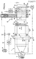
- the device in FIG. 1 shows a shaping tool in the form of an extruder head 1, the extrusion channel 3 of which is connected to the extruder 2.
- the extruder head 1 is made from two halves 8, 8 'which are longitudinally divided in the extrusion plane II-II and which enclose a displacement body 9 between them and form the flow channels 4, 4' with the latter. Starting from the extrusion channel 3, these broaden to the bandwidth in initially upward and downward flow paths 40, 40 '. They then flow around the displacer 9 approximately parallel to the extrusion plane II-II and unite in flow paths 42, 42 'directed upwards and downwards against one another and at an acute angle to the extrusion plane in the angle of incidence area 41.
- the displacer body 9 is longitudinally divided into two halves 9 'and 9 "in the extrusion plane II-II. These form between them a breakthrough 10 running transversely to the extrusion direction for receiving the slide 11, on which the tongue 12, which in turn is arranged is guided in a guide 13 starting from the opening 10 and opening in the impact angle region 41.
- the slide 11 protrudes a little from the opening 10 on the side of the tool and is connected to a frame 14 on which a drive device (not shown) for moving the slide 11
- the sc shown in Fig. 1 in the advanced position slider 11 with the tongue 12, which is also shown in the advanced position, has springs 15 as reset elements, which return it to the starting position.
- the tongue 12 penetrates between the extrusion flows 42, 42 'in the incidence angle region 41 to such an extent that it displaces a spatial unit approximately corresponding to a stiffening body 18.
- the slide 11 and the tongue 12 are retracted, thereby leaving a slot-shaped cavity 17 in the band 16.
- the working stroke of the tongue 12 is designated A. It is important that the working stroke path is completely outside, at least by the width of the cavity generated in each case the mouthpiece 6 is. This is the only way to ensure that the cavity formed by the tongue is retained in its full width.
- an injection nozzle 19 opens from one side, specifically from that at which the cavities 17 remain open on one side.
- Air or air / water mixture is preferably thereby already during the advancement of the tongue 12 or air is introduced with an anti-adhesive into the resulting cavity 17 and thereby prevents the latter from sticking together in the slot channel 5 as the tape 16 is advanced further.
- the open end of the resulting cavity 17 reaches the area of the injection nozzle 19
- its opening is released from the extrusion medium and a separation medium enters the cavity 17 under pressure.
- This causes the cavity to expand, cools its inner walls, solidifies it and, if necessary, covers it with an anti-adhesive.
- a powder such as talc, stearate, chalk or the like.
- the band 16 After completion of its shaping as a prefabricated joint sealing band with prefabricated cavities 1, reaches the insertion station 21.
- This comprises a magazine 22 containing the stiffening body 18 and a mechanically actuatable slide 23.
- the function of this insertion station 21 consists in this to insert the stiffening bodies 18 into the prepared cavities 17 so far that their ends are equidistant from the edges 46, 46 'in the interior of the strip 16.
- the insertion station 21 has a guide 38.
- the welding station 26 is arranged in the extrusion direction 20. This has the function of hermetically sealing the ends of the cavities 17 that are still open on one side after the insertion of the stiffening bodies 18 by welding.
- welding station 26 comprises a hot air generator 27 and a welding nozzle 28.
- Fig. 2 shows the device in plan view.
- the same functional elements are identified by the same reference numbers.
- the top view clearly shows the arrangement and functional sequence of the individual device parts and stations in the extrusion direction 20 from the tongue 12 penetrating in the angle of incidence area 41 with the movement area A and the injection nozzle 19 and via the insertion station 21 to finally the welding station 26.
- the exemplary embodiment shown is the frame 14 of the slide 11 in connection with a mechanical drive device 29. As shown, for example, this can be designed as a pneumatically or hydraulically actuated piston / cylinder unit. However, any other type of kinematic drive device is conceivable, e.g. Cam drive, cam disc drive, eccentric drive and the like.
- the insertion station 21 comprises the magazine 22 with the stiffening bodies 18 and also a slide 23 which is also driven mechanically, electrically or in another way in connection with a control device 30.
- This comprises a compressed air source 31, a compressed air line 32, a control valve 33, a regulator 34 , a timer 35, a tachometer generator 36 and a control line 37.
- the welding station 26 comprises the hot air generator 27 and the welding nozzle 28 and a guide 38 ', while the insertion station 21 is equipped with a guide 38.
- Fig. 2a shows the same device, but with an alternative drive of the slide 11.
- This interacts with a movement wedge 38, the working stroke, represented by the double arrow 39, causes a movement of the slide 11 in the direction of the double arrow 43.
- the drive of the motion wedge 38 can for example consist of a solenoid, not shown.
- an energy source in the form of a compressed air source 31 with a compressed air line 32 and a control valve 33 is provided, for example, which is controlled by a Controller 34 is controlled by the timer 35 at time intervals.
- This control can be equipped, for example, with a tachometer generator 36, which taps the feed speed of the belt 16 and applies a speed-proportional signal to the timer 35 via the control line 37.
- Fig. 3 shows the same device in section along section planes III-III in Fig. 2.
- the illustration shows the position of the tongue 12 in the angle of incidence 41, as well as the injection nozzle 19 opening there.
- the arrangement of the slide 11 and of the frame 14 connected to the slider is shown.
- the function of the device should be easily recognizable from FIGS. 1 to 3 and the associated explanations.
- the extrusion stream generated by the extruder 2 which flows around the displacer 9 in two sub-streams 4 and 4 ', merges with the sub-streams 42 and 42' in the angle of incidence area 41, forming the band 16.
- the slide 11 moves forward and with it the tongue 12, which penetrates between the extrusion partial flows 42, 42 'in the incidence angle region 41 and displaces a spatial unit.
- the tongue 12 is withdrawn and leaves a cavity 17 in the resulting band 16, which by blowing in air or Air-water mixture is prevented from collapsing with the help of the injection nozzle 19.
Landscapes
- Engineering & Computer Science (AREA)
- Mechanical Engineering (AREA)
- Chemical & Material Sciences (AREA)
- Composite Materials (AREA)
- Extrusion Moulding Of Plastics Or The Like (AREA)
- Lining Or Joining Of Plastics Or The Like (AREA)
Priority Applications (1)
| Application Number | Priority Date | Filing Date | Title |
|---|---|---|---|
| AT84104113T ATE41755T1 (de) | 1983-05-06 | 1984-04-12 | Verfahren und vorrichtung zur herstellung eines fugendichtungsbandes aus kunststoff mit vom bandprofil umschlossenen versteifungskoerpern, sowie nach dem verfahren hergestelltes fugendichtungsband. |
Applications Claiming Priority (2)
| Application Number | Priority Date | Filing Date | Title |
|---|---|---|---|
| CH2488/83A CH663755A5 (de) | 1983-05-06 | 1983-05-06 | Verfahren und vorrichtung zur herstellung eines fugendichtungsbandes aus kunststoff mit vom bandprofil umschlossenen versteifungskoerpern, sowie fugendichtungsband. |
| CH2488/83 | 1983-05-06 |
Publications (3)
| Publication Number | Publication Date |
|---|---|
| EP0126277A2 true EP0126277A2 (fr) | 1984-11-28 |
| EP0126277A3 EP0126277A3 (en) | 1985-07-10 |
| EP0126277B1 EP0126277B1 (fr) | 1989-03-29 |
Family
ID=4234930
Family Applications (1)
| Application Number | Title | Priority Date | Filing Date |
|---|---|---|---|
| EP84104113A Expired EP0126277B1 (fr) | 1983-05-06 | 1984-04-12 | Procédé et dispositif pour la production d'un profilé d'étanchéité en matière plastique avec des corps renforçants enveloppés par le profilé ainsi que profilé d'étanchéité produit selon ce procédé |
Country Status (4)
| Country | Link |
|---|---|
| EP (1) | EP0126277B1 (fr) |
| AT (1) | ATE41755T1 (fr) |
| CH (1) | CH663755A5 (fr) |
| DE (1) | DE3477480D1 (fr) |
Cited By (3)
| Publication number | Priority date | Publication date | Assignee | Title |
|---|---|---|---|---|
| DE3617966A1 (de) * | 1986-05-28 | 1987-12-03 | Janol Gmbh & Co Kg | Verfahren zum herstellen von fugendichtungsbaendern fuer gebaeudefugen und vorrichtung zur durchfuehrung des verfahrens |
| DE4220896C1 (en) * | 1992-06-25 | 1993-05-19 | Euroteam Gmbh Fuer Bauwerkerhaltung, 1000 Berlin, De | Prodn. of dual component material sealing band made of extruded plastics |
| DE4413599A1 (de) * | 1994-04-21 | 1995-10-26 | Beko Renate Lang | Verfahren zur Herstellung von innen liegenden Fugenbändern |
Family Cites Families (6)
| Publication number | Priority date | Publication date | Assignee | Title |
|---|---|---|---|---|
| DE841782C (de) * | 1951-02-15 | 1952-06-19 | Ruschhaupt Geb | Verfahren und Vorrichtung zur Bildung von Hohlraeumen in plastischer Masse |
| US3488808A (en) * | 1964-12-07 | 1970-01-13 | American Optical Corp | Apparatus for making spectacle temple blanks |
| DE1704595A1 (de) * | 1967-11-09 | 1970-05-14 | Dynamit Nobel Ag | Verfahren und Vorrichtung zur Herstellung von Brillenbuegelrohlingen |
| DE1921788A1 (de) * | 1969-04-29 | 1971-02-04 | Gruenzweig & Hartmann | Verfahren zur Herstellung von mit Metalleinlagen versehenen Kunststoffprofilen |
| FR2441481A1 (fr) * | 1978-11-17 | 1980-06-13 | Lignes Telegraph Telephon | Procede de fabrication de profiles cylindriques alveoles |
| DE2926581C2 (de) * | 1979-06-30 | 1985-05-30 | Besaplast Inhaber Heinz Bentler, 4236 Hamminkeln | Verfahren zum Herstellen eines Fugenbandes für aufgehende Gebäudewände im Hoch- und Tiefbau sowie Vorrichtung zur Durchführung des Verfahrens |
-
1983
- 1983-05-06 CH CH2488/83A patent/CH663755A5/de not_active IP Right Cessation
-
1984
- 1984-04-12 AT AT84104113T patent/ATE41755T1/de not_active IP Right Cessation
- 1984-04-12 EP EP84104113A patent/EP0126277B1/fr not_active Expired
- 1984-04-12 DE DE8484104113T patent/DE3477480D1/de not_active Expired
Cited By (3)
| Publication number | Priority date | Publication date | Assignee | Title |
|---|---|---|---|---|
| DE3617966A1 (de) * | 1986-05-28 | 1987-12-03 | Janol Gmbh & Co Kg | Verfahren zum herstellen von fugendichtungsbaendern fuer gebaeudefugen und vorrichtung zur durchfuehrung des verfahrens |
| DE4220896C1 (en) * | 1992-06-25 | 1993-05-19 | Euroteam Gmbh Fuer Bauwerkerhaltung, 1000 Berlin, De | Prodn. of dual component material sealing band made of extruded plastics |
| DE4413599A1 (de) * | 1994-04-21 | 1995-10-26 | Beko Renate Lang | Verfahren zur Herstellung von innen liegenden Fugenbändern |
Also Published As
| Publication number | Publication date |
|---|---|
| DE3477480D1 (en) | 1989-05-03 |
| EP0126277A3 (en) | 1985-07-10 |
| CH663755A5 (de) | 1988-01-15 |
| ATE41755T1 (de) | 1989-04-15 |
| EP0126277B1 (fr) | 1989-03-29 |
Similar Documents
| Publication | Publication Date | Title |
|---|---|---|
| DE2155888C3 (de) | Verfahren zum Herstellen von Bürsten bzw. Bürstenkörpern | |
| DE2115383C3 (de) | Verfahren zum Herstellen eines teilbaren Reißverschlusses | |
| DE69215361T2 (de) | Blasformverfahren, unter druck stehende flüssigkeitseinspritzvorrichtung und auswurfvorrichtung | |
| DE102007025296A1 (de) | Vorrichtung zur Extrusion von bahn- oder bänderförmigen Vorformlingen aus thermoplastischem Kunststoff sowie Verfahren zur Extrusion eines solchen Vorformlings | |
| EP1144177B1 (fr) | Dispositif d'injection utilise pour doubler un materiau de superstructure avec du plastique et procede | |
| DE2039191A1 (de) | Verfahren und Vorrichtung zur Herstellung von an den Enden von Reissverschluessen vorgeschenen Endstuecken | |
| DE2702426A1 (de) | Verfahren und vorrichtung zur herstellung von reissverschluessen | |
| EP0126277B1 (fr) | Procédé et dispositif pour la production d'un profilé d'étanchéité en matière plastique avec des corps renforçants enveloppés par le profilé ainsi que profilé d'étanchéité produit selon ce procédé | |
| DE3443723C2 (de) | Verfahren und Vorrichtung zum Herstellen eines Kunststoff-Körpers mit wenigstens einem langen Rohr ohne Konizität | |
| AT393647B (de) | Verfahren und vorrichtung zum extrudieren eines bandprofils | |
| DE2926581C2 (de) | Verfahren zum Herstellen eines Fugenbandes für aufgehende Gebäudewände im Hoch- und Tiefbau sowie Vorrichtung zur Durchführung des Verfahrens | |
| DE3543767A1 (de) | Verfahren und vorrichtung zur kontinuierlichen herstellung von mit kunststoff ausgeschaeumten profilen | |
| DE2442866C3 (de) | Vorrichtung zur Herstellung eines Profilrohres aus Kunststoff | |
| EP1060862B1 (fr) | Methode de moulage par injection et moule pour utiliser cette méthode de moulage | |
| DE3525133C2 (fr) | ||
| DE2924871A1 (de) | Verfahren und vorrichtung zum verbinden der gegenueberliegenden schenkel von gegossenen reissverschlusskuppelgliedern | |
| DE1450348B2 (de) | Verfahren zur Herstellung eines Rohres oder Behälters aus einem mit einer Verstärkungseinlage verstärkten Band aus Kunststoff | |
| DE102016224581B3 (de) | Vorrichtung und Verfahren zum Herstellen von Objekten aus einer erstarrenden Formmasse mit Schiebereinrichtung | |
| DE2743546A1 (de) | Verfahren und vorrichtung zum spritzgiessen von reissverschluessen | |
| DE2739682C2 (de) | Kunststoffrohr mit in bestimmten Abständen angeordneten Verdickungen und Vorrichtung zur Herstellung desselben | |
| DE1179356B (de) | Vorrichtung zum Herstellen von Schlaeuchen aus thermoplastischem Material, insbesondere thermoplastischen Kunststoffen | |
| DE19722612C1 (de) | Vorrichtung zum Spritzgießen eines Werkstückes aus mindestens zwei unterschiedlichen Materialkomponenten | |
| DE422989C (de) | Giessform zur Herstellung von Durchschuessen und Linien | |
| DE3119662C2 (fr) | ||
| DE586788C (de) | Verfahren und Vorrichtung zum Herstellen von Hohlsteinen mit mehreren durch Querwaende unterteilten Hohlraeumen |
Legal Events
| Date | Code | Title | Description |
|---|---|---|---|
| PUAI | Public reference made under article 153(3) epc to a published international application that has entered the european phase |
Free format text: ORIGINAL CODE: 0009012 |
|
| AK | Designated contracting states |
Designated state(s): AT DE FR IT |
|
| PUAL | Search report despatched |
Free format text: ORIGINAL CODE: 0009013 |
|
| AK | Designated contracting states |
Designated state(s): AT DE FR IT |
|
| 17P | Request for examination filed |
Effective date: 19860110 |
|
| 17Q | First examination report despatched |
Effective date: 19860811 |
|
| R17C | First examination report despatched (corrected) |
Effective date: 19870603 |
|
| GRAA | (expected) grant |
Free format text: ORIGINAL CODE: 0009210 |
|
| AK | Designated contracting states |
Kind code of ref document: B1 Designated state(s): AT DE FR IT |
|
| REF | Corresponds to: |
Ref document number: 41755 Country of ref document: AT Date of ref document: 19890415 Kind code of ref document: T |
|
| ITF | It: translation for a ep patent filed | ||
| REF | Corresponds to: |
Ref document number: 3477480 Country of ref document: DE Date of ref document: 19890503 |
|
| ET | Fr: translation filed | ||
| PLBI | Opposition filed |
Free format text: ORIGINAL CODE: 0009260 |
|
| 26 | Opposition filed |
Opponent name: BESAPLAST BENTLER GMBH Effective date: 19891223 |
|
| ITTA | It: last paid annual fee | ||
| PLAB | Opposition data, opponent's data or that of the opponent's representative modified |
Free format text: ORIGINAL CODE: 0009299OPPO |
|
| R26 | Opposition filed (corrected) |
Opponent name: BESAPLAST KUNSTSTOFF GMBH Effective date: 19891223 |
|
| PLBN | Opposition rejected |
Free format text: ORIGINAL CODE: 0009273 |
|
| STAA | Information on the status of an ep patent application or granted ep patent |
Free format text: STATUS: OPPOSITION REJECTED |
|
| 27O | Opposition rejected |
Effective date: 19920504 |
|
| PGFP | Annual fee paid to national office [announced via postgrant information from national office to epo] |
Ref country code: FR Payment date: 19990310 Year of fee payment: 16 |
|
| PGFP | Annual fee paid to national office [announced via postgrant information from national office to epo] |
Ref country code: AT Payment date: 19990419 Year of fee payment: 16 |
|
| PGFP | Annual fee paid to national office [announced via postgrant information from national office to epo] |
Ref country code: DE Payment date: 19990615 Year of fee payment: 16 |
|
| PG25 | Lapsed in a contracting state [announced via postgrant information from national office to epo] |
Ref country code: AT Free format text: LAPSE BECAUSE OF NON-PAYMENT OF DUE FEES Effective date: 20000412 |
|
| PG25 | Lapsed in a contracting state [announced via postgrant information from national office to epo] |
Ref country code: FR Free format text: LAPSE BECAUSE OF NON-PAYMENT OF DUE FEES Effective date: 20001229 |
|
| PG25 | Lapsed in a contracting state [announced via postgrant information from national office to epo] |
Ref country code: DE Free format text: LAPSE BECAUSE OF NON-PAYMENT OF DUE FEES Effective date: 20010201 |
|
| REG | Reference to a national code |
Ref country code: FR Ref legal event code: ST |