EP0126332A2 - Kennkartenaufnehmer - Google Patents
Kennkartenaufnehmer Download PDFInfo
- Publication number
- EP0126332A2 EP0126332A2 EP84104693A EP84104693A EP0126332A2 EP 0126332 A2 EP0126332 A2 EP 0126332A2 EP 84104693 A EP84104693 A EP 84104693A EP 84104693 A EP84104693 A EP 84104693A EP 0126332 A2 EP0126332 A2 EP 0126332A2
- Authority
- EP
- European Patent Office
- Prior art keywords
- slideway
- halves
- key card
- insert
- pedestals
- Prior art date
- Legal status (The legal status is an assumption and is not a legal conclusion. Google has not performed a legal analysis and makes no representation as to the accuracy of the status listed.)
- Granted
Links
Images

Classifications
-
- G—PHYSICS
- G06—COMPUTING OR CALCULATING; COUNTING
- G06K—GRAPHICAL DATA READING; PRESENTATION OF DATA; RECORD CARRIERS; HANDLING RECORD CARRIERS
- G06K13/00—Conveying record carriers from one station to another, e.g. from stack to punching mechanism
- G06K13/02—Conveying record carriers from one station to another, e.g. from stack to punching mechanism the record carrier having longitudinal dimension comparable with transverse dimension, e.g. punched card
- G06K13/08—Feeding or discharging cards
Definitions
- Key card receivers are widely used to receive key cards which are partially or fully slid into the receiver. Identification or data is read from the card before the card is withdrawn.
- the receiver must be sturdy for repeated use and for accuracy in reading identification or data from the card.
- the receivers must have adequate space for receiving the card and holding electronic circuitry to read information from the card.
- the invention overcomes problems existing in the prior art and constructs a sturdy and compact card receiver with three parts which interconnect and rigidify each other and which can be readily formed with conventional processes.
- a preferred key card receiver apparatus has a key car slideway front insert, a first body half and a second opposite complementary body half.
- First front vestibule means in the first body half and second complementary front vestibule means in the second body half receive the key card slideway insert.
- a first rear chamber in the first body half and a second complementary rear chamber in.the second body half form a body chamber for holding an electronic reading circuit.
- the first and second body halves include complementary opposite projections and recesses. In the preferred embodiments the recesses and projections are on pedestals which extend toward the opposite body halves.
- First and second mounting means are aligned in the first and second halves.
- the first and second mounting means are formed with first and second mounting pedestals mounted within the halves and extend toward the opposite halves. Aligned bores extend through the pedestals.
- a preferred key card slideway insert has a front face which abuts ends of the first and second body halves.
- a tapered guideway extends inward from the body face, and a flat slideway extends inward from the guideway.
- the key card slideway insert further has parallel walls on opposite sides of the slideway extending generally perpendicular to the slideway. Abutments are connected to the parallel walls and extend generally outward therefrom. Preferred abutments include hooks for partially surrounding pedestals extending inward from the first and second body halves.
- the abutments further include projections.
- a jack mounted on one body half has a recess for receiving the projections on the key card slideway insert.
- the abutment has a wall facing toward the rear chamber and the projections are on the wall.
- a jack has an open end for receiving an end of a key card and has an opposite end with corner portions for receiving pedestals in the first body half. Recesses adjacent the open end of the jack receive projections on the slideway rearward facing walls, whereby the projections and the rearward facing walls hold the corner portions and the jack against the pedestal.
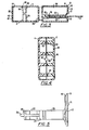
- a key card receiver is generally indicated by the numeral 1.
- the receiver preferably is made of a lower body half 2, an upper body half 4 with a key card receiver insert 6 as a frontal piece.
- a key card 8 is partially slid into an opening 10 in the receiver.
- the slideway opening 10 is surrounded by a tapered guideway 12 which leads inward from the face 14 of insert 6.
- the guideway 12 centers the card 8 as it is inserted in the receiver and directs the card toward the slideway opening 10.
- the lower body 2 has a front edge which abuts a recess 16 in the edge 18 of insert 6.
- the recess 16 extends around the edge 18 and aids in holding the insert precisely centered between the body halves.
- Upper and lower flat slideway walls 20 and 22, as shown in Figure 3, are bordered by perpendicular side walls 24 and 26 which extend perpendicular to the walls 20 and 22 of the slideway.
- Abutment means 30 and 32 include elongated hooks 34, walls 36 and tongues 38 which fit in jack recesses, as later described.
- the lower body half 2 has side walls 42 and 44, a rear wall 46 and a bottom wall 48.
- Pedestals 50 near the rear wall 46 have knobs 52 or holes 54 which cooperate with complementary holes and knobs on pedestals of the opposite body half.
- Mounting pedestals 56, 58 and 60 have openings therethrough for receiving mounting bolts.
- the forward pedestals 58 receive the hooks 34 of the slideway insert.
- the hooks 34 and the notches 16 longitudinally fix the slideway insert with respect to the body half.
- Bores 62 and 64 in the mounting pedestals 56 and 58 are countersunk, 66 and 68, to receive fasteners, as shown in Figures 1 and 3.
- jack 70 is held in place against central pedestals 60 by projections 38 on rear walls 36 of the slideway insert 6. Rear corners 72 of the jack 70 are held against the pedestal 60 by abutment of wall 36 with front walls 74 of the jack.
- Jack 70 has inward facing contacts (not shown) which are complementary to outward facing contacts on the end of card 8.
- the forward facing end 76 of jack 70 is open to receive the end of the card.
- Jack 70 may have either downward facing contacts or upward facing contacts or both. Conductors similarly connect the contacts to a circuit which converts the simultaneous information received by the contacts to pulse trains.
- the upper housing half 4 is identical to the lower housing half 2 so that the parts are interchangeable and may be made in the same die.
- a hole 80 is formed by semicircular openings between the halves in the rear wall 46.
- a separate hole 82 is subsequently formed in one of the halves.
- the two halves provide a rearward chamber 84 for holding electronic circuits and a forward vestibule 86 for holding the key card slideway insert 6.
- the elements are assembled by placing the jack 70 on the key card slideway insert 6, by placing recesses 78 on lugs 38. Then, the assembled jack 70 and slideway insert 6 are slid down into lower body half 2 with the hooks 34 behind the pedestals 58 and forward edges of the side walls of the body insert engaging grooves 16 in edge 18 of the insert 6. Jack 70 is trapped between the insert 6 and the forward walls of central pedestals 60.
- the electronic circuit is added in the chamber 84 and its communication wire is fed through the partially formed hole 80 in the rear wall 46.
- the upper half 4 is placed over the lower half, and the sections are bolted together with four fasteners which extend through bores 62 and 64.
- the receiver is mounted in an appropriate position, for example, in a vehicle, and it is ready to receive a card 8.
Landscapes
- Physics & Mathematics (AREA)
- General Physics & Mathematics (AREA)
- Engineering & Computer Science (AREA)
- Theoretical Computer Science (AREA)
- Lock And Its Accessories (AREA)
Applications Claiming Priority (2)
| Application Number | Priority Date | Filing Date | Title |
|---|---|---|---|
| US496042 | 1983-05-19 | ||
| US06/496,042 US4547661A (en) | 1983-05-19 | 1983-05-19 | Key card receiver |
Publications (3)
| Publication Number | Publication Date |
|---|---|
| EP0126332A2 true EP0126332A2 (de) | 1984-11-28 |
| EP0126332A3 EP0126332A3 (en) | 1985-04-17 |
| EP0126332B1 EP0126332B1 (de) | 1987-07-08 |
Family
ID=23971010
Family Applications (1)
| Application Number | Title | Priority Date | Filing Date |
|---|---|---|---|
| EP84104693A Expired EP0126332B1 (de) | 1983-05-19 | 1984-04-26 | Kennkartenaufnehmer |
Country Status (6)
| Country | Link |
|---|---|
| US (1) | US4547661A (de) |
| EP (1) | EP0126332B1 (de) |
| AU (1) | AU572834B2 (de) |
| CA (1) | CA1217106A (de) |
| DE (1) | DE3464684D1 (de) |
| ZA (1) | ZA843349B (de) |
Cited By (2)
| Publication number | Priority date | Publication date | Assignee | Title |
|---|---|---|---|---|
| EP0307787A1 (de) * | 1987-09-11 | 1989-03-22 | Siemens Aktiengesellschaft | Gehäuse für einen Chipkartenleser |
| CH682775A5 (fr) * | 1990-03-23 | 1993-11-15 | Landis & Gyr Communications Su | Lecteur de carte. |
Families Citing this family (1)
| Publication number | Priority date | Publication date | Assignee | Title |
|---|---|---|---|---|
| US4802027A (en) * | 1987-10-05 | 1989-01-31 | Pitney Bowes Inc. | Data storage device coupled to a data storage interface |
Family Cites Families (7)
| Publication number | Priority date | Publication date | Assignee | Title |
|---|---|---|---|---|
| AU478754B2 (en) * | 1974-02-14 | 1975-08-14 | Access Control Systems (Australia) Pty. Ltd. | Magnetic identification apparatus |
| US4097728A (en) * | 1974-01-02 | 1978-06-27 | Monitron Industries | Apparatus for providing and sensing coded information |
| CH609711A5 (de) * | 1976-04-27 | 1979-03-15 | Roussel Uclaf | |
| US4149027A (en) * | 1977-05-27 | 1979-04-10 | Atari, Inc. | TV game cartridge and method |
| US4480180A (en) * | 1981-05-07 | 1984-10-30 | Fisher Charles R | Cartridge assembly for data-sensing system |
| DE8126368U1 (de) * | 1981-09-10 | 1982-03-11 | Licentia Patent-Verwaltungs-Gmbh, 6000 Frankfurt | Gehäuse für ein elektronisches Gerät |
| US4443693A (en) * | 1982-03-08 | 1984-04-17 | Sealectro Corporation | Electro-optical badge reader |
-
1983
- 1983-05-19 US US06/496,042 patent/US4547661A/en not_active Expired - Lifetime
-
1984
- 1984-04-24 CA CA000452623A patent/CA1217106A/en not_active Expired
- 1984-04-26 EP EP84104693A patent/EP0126332B1/de not_active Expired
- 1984-04-26 DE DE8484104693T patent/DE3464684D1/de not_active Expired
- 1984-04-30 AU AU27496/84A patent/AU572834B2/en not_active Ceased
- 1984-05-04 ZA ZA843349A patent/ZA843349B/xx unknown
Cited By (2)
| Publication number | Priority date | Publication date | Assignee | Title |
|---|---|---|---|---|
| EP0307787A1 (de) * | 1987-09-11 | 1989-03-22 | Siemens Aktiengesellschaft | Gehäuse für einen Chipkartenleser |
| CH682775A5 (fr) * | 1990-03-23 | 1993-11-15 | Landis & Gyr Communications Su | Lecteur de carte. |
Also Published As
| Publication number | Publication date |
|---|---|
| EP0126332A3 (en) | 1985-04-17 |
| AU2749684A (en) | 1984-11-22 |
| ZA843349B (en) | 1984-12-24 |
| CA1217106A (en) | 1987-01-27 |
| AU572834B2 (en) | 1988-05-19 |
| DE3464684D1 (en) | 1987-08-13 |
| US4547661A (en) | 1985-10-15 |
| EP0126332B1 (de) | 1987-07-08 |
Similar Documents
| Publication | Publication Date | Title |
|---|---|---|
| US5129594A (en) | Avionic tray and method of making same | |
| GB2206431B (en) | Data card circuits | |
| JP2000506316A (ja) | 電気機器のモジュール | |
| US4586254A (en) | Method of making a modular connector | |
| US4555619A (en) | Driver key car identifying system | |
| US4547661A (en) | Key card receiver | |
| US6179650B1 (en) | Modularized electric connector | |
| KR940003239B1 (ko) | 인쇄된 회로판을 프레임에 지지시키는 장치 | |
| EP1113714A3 (de) | Baugruppen, Baugruppenträger und Baugruppenanordnungen | |
| US5007846A (en) | Specialized frame for retaining an edge connector on a printed circuit board | |
| EP0210686A2 (de) | Elektrischer Steckverbinder mit Montierglied | |
| EP0133189A2 (de) | Modularer Steckverbinder | |
| US6157536A (en) | Retention module for receiving different CPU modules | |
| EP0908979A3 (de) | Kartensteckverbinderanordnung | |
| JPS5935028Y2 (ja) | プリント基板収容筐体 | |
| US5315487A (en) | Method and device for coding printed circuit boards | |
| EP0136853A1 (de) | Hülle für einen Vielfachstecker für elektrische Verbindungen mit gedruckten Schaltungen | |
| US6065611A (en) | Combination rack for holding a computer mainframe and an expansion unit | |
| JPS60153589U (ja) | 印刷配線基板插抜工具 | |
| JPS5862573U (ja) | 配線分岐箱 | |
| GB2301492A (en) | Flexible-board connector | |
| JPS6035652U (ja) | 移動用通信装置構造 | |
| JPS6113693A (ja) | 車載用機器取出機構 | |
| JPS6444684U (de) | ||
| JPH0623177U (ja) | メモリーカード用コネクタ |
Legal Events
| Date | Code | Title | Description |
|---|---|---|---|
| PUAI | Public reference made under article 153(3) epc to a published international application that has entered the european phase |
Free format text: ORIGINAL CODE: 0009012 |
|
| AK | Designated contracting states |
Designated state(s): BE CH DE FR GB IT LI NL SE |
|
| PUAL | Search report despatched |
Free format text: ORIGINAL CODE: 0009013 |
|
| AK | Designated contracting states |
Designated state(s): BE CH DE FR GB IT LI NL SE |
|
| RHK1 | Main classification (correction) |
Ipc: H05K 5/00 |
|
| 17P | Request for examination filed |
Effective date: 19850927 |
|
| 17Q | First examination report despatched |
Effective date: 19861008 |
|
| ITF | It: translation for a ep patent filed | ||
| GRAA | (expected) grant |
Free format text: ORIGINAL CODE: 0009210 |
|
| AK | Designated contracting states |
Kind code of ref document: B1 Designated state(s): BE CH DE FR GB IT LI NL SE |
|
| ET | Fr: translation filed | ||
| REF | Corresponds to: |
Ref document number: 3464684 Country of ref document: DE Date of ref document: 19870813 |
|
| PLBE | No opposition filed within time limit |
Free format text: ORIGINAL CODE: 0009261 |
|
| STAA | Information on the status of an ep patent application or granted ep patent |
Free format text: STATUS: NO OPPOSITION FILED WITHIN TIME LIMIT |
|
| 26N | No opposition filed | ||
| ITTA | It: last paid annual fee | ||
| EAL | Se: european patent in force in sweden |
Ref document number: 84104693.1 |
|
| PGFP | Annual fee paid to national office [announced via postgrant information from national office to epo] |
Ref country code: NL Payment date: 19990331 Year of fee payment: 16 Ref country code: FR Payment date: 19990331 Year of fee payment: 16 |
|
| PGFP | Annual fee paid to national office [announced via postgrant information from national office to epo] |
Ref country code: SE Payment date: 19990401 Year of fee payment: 16 Ref country code: GB Payment date: 19990401 Year of fee payment: 16 |
|
| PGFP | Annual fee paid to national office [announced via postgrant information from national office to epo] |
Ref country code: DE Payment date: 19990402 Year of fee payment: 16 |
|
| PGFP | Annual fee paid to national office [announced via postgrant information from national office to epo] |
Ref country code: CH Payment date: 19990407 Year of fee payment: 16 |
|
| PGFP | Annual fee paid to national office [announced via postgrant information from national office to epo] |
Ref country code: BE Payment date: 19990422 Year of fee payment: 16 |
|
| PG25 | Lapsed in a contracting state [announced via postgrant information from national office to epo] |
Ref country code: GB Free format text: LAPSE BECAUSE OF NON-PAYMENT OF DUE FEES Effective date: 20000426 |
|
| PG25 | Lapsed in a contracting state [announced via postgrant information from national office to epo] |
Ref country code: SE Free format text: LAPSE BECAUSE OF NON-PAYMENT OF DUE FEES Effective date: 20000427 |
|
| PG25 | Lapsed in a contracting state [announced via postgrant information from national office to epo] |
Ref country code: LI Free format text: LAPSE BECAUSE OF NON-PAYMENT OF DUE FEES Effective date: 20000430 Ref country code: CH Free format text: LAPSE BECAUSE OF NON-PAYMENT OF DUE FEES Effective date: 20000430 Ref country code: BE Free format text: LAPSE BECAUSE OF NON-PAYMENT OF DUE FEES Effective date: 20000430 |
|
| NLS | Nl: assignments of ep-patents |
Owner name: MERITOR LIGHT VEHICLE TECHNOLOGY,LLC A DELAWARE LI |
|
| NLT1 | Nl: modifications of names registered in virtue of documents presented to the patent office pursuant to art. 16 a, paragraph 1 |
Owner name: MERITOR LIGHT VEHICLE SYSTEMS, INC. |
|
| REG | Reference to a national code |
Ref country code: FR Ref legal event code: TP Ref country code: FR Ref legal event code: CD |
|
| BERE | Be: lapsed |
Owner name: MERITOR LIGHT VEHICLE TECHNOLOGY LLC A DELAWARE L Effective date: 20000430 |
|
| PG25 | Lapsed in a contracting state [announced via postgrant information from national office to epo] |
Ref country code: NL Free format text: LAPSE BECAUSE OF NON-PAYMENT OF DUE FEES Effective date: 20001101 |
|
| EUG | Se: european patent has lapsed |
Ref document number: 84104693.1 |
|
| GBPC | Gb: european patent ceased through non-payment of renewal fee |
Effective date: 20000426 |
|
| REG | Reference to a national code |
Ref country code: CH Ref legal event code: PL |
|
| PG25 | Lapsed in a contracting state [announced via postgrant information from national office to epo] |
Ref country code: FR Free format text: LAPSE BECAUSE OF NON-PAYMENT OF DUE FEES Effective date: 20001229 |
|
| BECH | Be: change of holder |
Free format text: 20000516 *MERITOR LIGHT VEHICLE TECHNOLOGY LLC A DELAWARE LLC |
|
| BECN | Be: change of holder's name |
Effective date: 20000516 |
|
| NLV4 | Nl: lapsed or anulled due to non-payment of the annual fee |
Effective date: 20001101 |
|
| PG25 | Lapsed in a contracting state [announced via postgrant information from national office to epo] |
Ref country code: DE Free format text: LAPSE BECAUSE OF NON-PAYMENT OF DUE FEES Effective date: 20010201 |
|
| REG | Reference to a national code |
Ref country code: FR Ref legal event code: ST |