EP0126458A2 - Farbbildkathodenstrahlröhre - Google Patents
Farbbildkathodenstrahlröhre Download PDFInfo
- Publication number
- EP0126458A2 EP0126458A2 EP84105674A EP84105674A EP0126458A2 EP 0126458 A2 EP0126458 A2 EP 0126458A2 EP 84105674 A EP84105674 A EP 84105674A EP 84105674 A EP84105674 A EP 84105674A EP 0126458 A2 EP0126458 A2 EP 0126458A2
- Authority
- EP
- European Patent Office
- Prior art keywords
- pole pieces
- magnetic field
- central plane
- ray tube
- cathode ray
- Prior art date
- Legal status (The legal status is an assumption and is not a legal conclusion. Google has not performed a legal analysis and makes no representation as to the accuracy of the status listed.)
- Granted
Links
Images




Classifications
-
- H—ELECTRICITY
- H01—ELECTRIC ELEMENTS
- H01J—ELECTRIC DISCHARGE TUBES OR DISCHARGE LAMPS
- H01J29/00—Details of cathode-ray tubes or of electron-beam tubes of the types covered by group H01J31/00
- H01J29/46—Arrangements of electrodes and associated parts for generating or controlling the ray or beam, e.g. electron-optical arrangement
- H01J29/56—Arrangements for controlling cross-section of ray or beam; Arrangements for correcting aberration of beam, e.g. due to lenses
-
- H—ELECTRICITY
- H01—ELECTRIC ELEMENTS
- H01J—ELECTRIC DISCHARGE TUBES OR DISCHARGE LAMPS
- H01J29/00—Details of cathode-ray tubes or of electron-beam tubes of the types covered by group H01J31/00
- H01J29/46—Arrangements of electrodes and associated parts for generating or controlling the ray or beam, e.g. electron-optical arrangement
- H01J29/70—Arrangements for deflecting ray or beam
- H01J29/701—Systems for correcting deviation or convergence of a plurality of beams by means of magnetic fields at least
- H01J29/707—Arrangements intimately associated with parts of the gun and co-operating with external magnetic excitation devices
Definitions
- the present invention relates to a color cathode ray tube apparatus of a type which comprises deflection yoke for pincushion type horizontal deflection magnetic field and barrel type vertical deflection magnetic field and in-line type electron gun..
- deflection yoke to be applied on a color cathode ray tube apparatus comprising in-line type electron gun is designed to produce pincushion type horizontal deflection magnetic field shown in FIG. 1 and barrel type vertical deflection magnetic field shown in FIG. 2. Therefore, such conventional color cathode ray tube apparatus does not require any complex convergence circuit, and can be constituted as a self-convergence system.
- such conventional apparatus has such problem that electron beam spots produced by projection on a phosphor screen from electron beam outlets of the in-line type electron gun make distortions to become elliptic shapes as shown in FIG. 3, as designated by b, g and r respectively for blue, green and red beam spots corresponding to the electron beams from the outlets B, G and R, thereby lowering resolution.
- the pincushion type horizontal deflection magnetic field can be decomposed as a superposition of uniform magnetic field la and positive six pole magnetic field component 2a, and . the barrel type vertical deflection magnetic field as a superposition of uniform magnetic field lb and negative six pole magnetic field component 2b.
- the distortions of the beam spots b, g and r are produced by the positive and negative six pole magnetic field components 2a and 2b as shown in FIG. 5(a) and FIG. 5(b).
- the beam spots distortion produces discolorations similar to those by misconvergences between central electron beam from the central electron gun and side electron beams from the side electron guns, thereby leading to poor resolution.
- the purpose of the present invention is to provide an improved color cathode ray tube apparatus having high resolution achieved by producing substantially circular beam spots on the entire phosphor screen of cathode ray tube without losing advantage of self-convergence function.
- the present invention is based on the inventors' studies and finding that, in view of major effects of magnetic fields at the outlet part of an electron gun on shape of beam spots, by provision of control magnetic pole pieces of a certain shape and disposition in magnetic field at the outlet part of the electron gun the shapes of beam spots on various parts of the phosphor screen are desirably corrected. That is, by superposing an additional negative six pole magnetic field component on conventional horizontal deflection magnetic field and by superposing an additional positive six pole magnetic field component on conventional vertical deflection magnetic field, improved pincushion type horizontal deflection magnetic field and barrel type vertical deflection magnetic field are obtainable, respectively.
- FIG. 6 A first preferred embodiment is described with reference to FIG. 6, FIG. 7, FIG. 8, FIG. 9, FIG. 10 and FIG. 11.
- the important feature of the present invention lies in configuration of electron gun of a cathode ray tube apparatus.
- the electron gun comprises a cathode 4, a control grid 5, a first acceleration electrode 6, a convergence electrode 7 and a final acceleration electrode 8.
- additional magnetic pole pieces 10 is provided by being held in a cap-shaped member 9 which is fixed on an outlet side end of the final acceleration electrode 8.
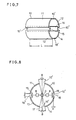
- the magnetic pole piece unit 10 is for adjusting magnetic field distribution of deflection magnetic field at the side of electron beam outlet of the electron gun, and conprises, as shown in FIG. 7 and FIG.
- the partial cylindrical pole pieces 11, 12, 13 and 14 which are shaped to have cross-sections of arc-shape disposed on an imaginary circle having its center on an axis of the electron gun.
- the partial cylindrical pole pieces 11, 12, 13 and 14 are substantially in symmetry with respect to vertical central plane and horizontal central plane each containing the electron gun axis thereon, and the pole pieces 11, 12, 13 ' and 14 are disposed with. circumferential gaps 10' on the vertical central plane and 10" on the horizontal central plane, respectively, between ends of neighboring ones.
- a pair of stripe-shaped narrow width pole pieces 15 and 16 are disposed as if covering the gaps 10" which crosses the horizontal central plane with a predetermined gap "a" from the imaginary circle on which.the arc-shaped pole pieces lie.
- the length of the narrow width stripe-shaped pole pieces 15 and 16 are substantially the same with the lengths of the arc-shaped pole pieces 11, 12, 13 and 14, and width of the pole pieces 15 and 16 are smaller than those of the pole pieces 11, 12, 13 and 14.
- the pole pieces 11, 12, 13 and 14 with arc-shaped sections are disposed on the circle which has a center on the axis of the electron gun, and the upper two pole pieces 11 and 12 make an upper pair which are disposed symmetry with respect to vertical central plane including the axis.
- the lower two pieces 13 and 14 also make symmetric pair with respect to the vertical central plane.
- the pole pieces 11 and 13 make a vertical symmetric pair with respect to horizontal central plane which includes the axis
- the other two pole pieces 12 and 14 also make another vertical symmetric pair with respect to the horizontal central plane.
- the fifth and sixth pole pieces 15 and 16 also make a symmetric pair with respect to the vertical plane.
- the vertical symmetric pair 11 and 13 or 12 and 14 make circumferential gap d between neighboring edges.
- the horizontal symmetric pair 11 and 12 or 13 and 14 makes gap which form angle of 20 with respect to the axis.
- the barrel type vertical deflection magnetic field is modified to that shown by solid lines from that by broken lines as shown in FIG. 9(a), at the outlet side of the electron gun into pincushion shape magnetic field distribution, thereby forming a component magnetic field of positive six pole magnetic field component.
- FIG. 9(b) shows decomposed components of the pincushion shape modified vertical deflection magnetic field of FIG. 9(a), which shows that the pincushion shape magnetic field is a superposition of horizontal uniform two pole magnetic field and a horizontal positive six pole magnetic field.
- the pincushion type horizontal deflection magnetic field is modified to that shown by solid lines from that by broken lines as shown in FIG. 10(a), at the outlet side of the electron gun into pincushion shape magnetic field distribution, thereby forming a component magnetic field of negative six pole magnetic field component.
- FIG. 10(b) shows decomposed components of the barrel shape modified horizontal deflection magnetic field of FIG. 10(a), which shows that the pincushion type magnetic field is a superposition of vertical uniform two pole magnetic field and a vertical negative six pole magnetic field.
- This barrel shape modification is produced by attracting actions by fifth magnetic pole piece 15 and six magnetic pole piece 16 as shown in FIG. 10(a).
- all beam spots in whole the parts of the phosphor screen including upper end, lower end, left end, right end, and four corner parts can achieve substantially circular shape as schematically shown in FIG. 11.
- Extent of compensation of shape of the beam spots to the substantially exact circle shape are determined by axial length L of the first, second, third, fourth, fifth and sixth magnetic pole pieces 11, 12, 13, 14, 15, 16, and angle 2A of the upper and lower circumferential gap opening seen from the central axis.
- the axial length L of the magnetic pole pieces should be longer, and the opening angle 8 should be smaller.
- the vertical gaps d is helpful in suppressing a decrease of horizontal deflection efficiency, and the fifth and sixth magnetic pole pieces 15, 16 serves to minimize difference of deflection distortions on horizontal line between two side electron beams from the electron beam outlets B and R.
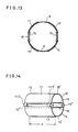
- FIG. 12 shows a modied example of the magnetic pole pieces which can be used instead of the magnetic pole pieces of FIG. 7 through FIG. 10. That is, a first, a second, a third and a fourth magnetic pole pieces 11, 12, 13, 14 have inside-bents 11', 12', 13' 14'. Such inside-bents are helpful in efficient modification into the pincushion shape vertical deflection magnetic field.
- the first through the sixth magnetic pole pieces 11-16 may be other shapes than exact arc section, that is the sectional shape can be consisting of part of polygonal shape, if the shape is substantially analogous to the arc shape.
- the magnetic pole pieces 11, 12, Vietnamese 16 may be disposed in such a manner that the arc-shaped magnetic pole pieces 11, 12, 13 and 14 are disposed outside of the cup-shaped member 9 and the fifth and sixth magnetic pole pieces 15, 16 are disposed inside the cup-shaped member 9.
- magnetic pole pieces 11 and 13 are made from a continuous sheet forming a. longitudinal slit 18 inbetween.
- the magnetic pole pieces 12 and 14 are also formed in the same manner.
- Bridging members ll13 and 1113' are provided to connect the upper magnetic pole piece 11 and the lower magnetic pole piece 13 therewith, but the bridging members 1113, 1113' are preferably shaped very narrow and bent outside, so as to produce a large magnetic reluctance therein.
- the magnetic pole pieces comprising first to sixth pole pieces can modify the vertical deflection magnetic field into the desirable pincushion shape distribution and also modify the horizontal deflection magnetic field into desirable barrel shape magnetic field distribution at the outlet side of the electron gun. And therefore, electron beam spots, hence illuminated spot on the phosphor.screen, of substantially good circle shape is obtainable on the entire phosphor screen without losing self-convergence effect.
Landscapes
- Video Image Reproduction Devices For Color Tv Systems (AREA)
Applications Claiming Priority (2)
| Application Number | Priority Date | Filing Date | Title |
|---|---|---|---|
| JP86994/83 | 1983-05-18 | ||
| JP58086994A JPS59214139A (ja) | 1983-05-18 | 1983-05-18 | カラ−受像管装置 |
Publications (3)
| Publication Number | Publication Date |
|---|---|
| EP0126458A2 true EP0126458A2 (de) | 1984-11-28 |
| EP0126458A3 EP0126458A3 (en) | 1986-05-07 |
| EP0126458B1 EP0126458B1 (de) | 1989-09-27 |
Family
ID=13902423
Family Applications (1)
| Application Number | Title | Priority Date | Filing Date |
|---|---|---|---|
| EP84105674A Expired EP0126458B1 (de) | 1983-05-18 | 1984-05-18 | Farbbildkathodenstrahlröhre |
Country Status (4)
| Country | Link |
|---|---|
| US (1) | US4600858A (de) |
| EP (1) | EP0126458B1 (de) |
| JP (1) | JPS59214139A (de) |
| DE (1) | DE3479941D1 (de) |
Families Citing this family (9)
| Publication number | Priority date | Publication date | Assignee | Title |
|---|---|---|---|---|
| US4728915A (en) * | 1986-03-18 | 1988-03-01 | Matsushita Electronics Corporation | Deflection yoke for a color cathode ray tube |
| NL8802194A (nl) * | 1988-09-06 | 1990-04-02 | Philips Nv | Coma-gecorrigeerd beeldweergeefsysteem. |
| US5068531A (en) * | 1991-04-04 | 1991-11-26 | Mobil Oil Corporation | Method and apparatus for producing a porosity log of a subsurface formation corrected for detector standoff |
| US5355050A (en) * | 1991-06-05 | 1994-10-11 | U.S. Philips Corporation | Color display tube with coma correction |
| US5300770A (en) * | 1992-08-10 | 1994-04-05 | Mobil Oil Corporation | Apparatus for producing a porosity log of a subsurface formation corrected for detector standoff |
| US5557164A (en) * | 1995-03-15 | 1996-09-17 | Chunghwa Picture Tubes, Ltd. | Cathode ray tube with misconvergence compensation |
| KR100260773B1 (ko) * | 1998-06-11 | 2000-07-01 | 손욱 | 칼라 음극선관의 네크부 지자계 차폐 테이프 |
| JP2005071859A (ja) * | 2003-08-26 | 2005-03-17 | Matsushita Electric Ind Co Ltd | 陰極線管装置 |
| US20110199027A1 (en) * | 2008-10-16 | 2011-08-18 | Yong Hwan Kim | Electron beam generator having adjustable beam width |
Family Cites Families (6)
| Publication number | Priority date | Publication date | Assignee | Title |
|---|---|---|---|---|
| US2880367A (en) * | 1956-08-31 | 1959-03-31 | Motorola Inc | Cathode ray tube apparatus |
| US3866080A (en) * | 1973-08-08 | 1975-02-11 | Rca Corp | Inline electron gun having magnetically permeable plates for enhancing convergence of electron beams |
| US4225804A (en) * | 1978-04-22 | 1980-09-30 | Gte Sylvania N.V. | Cathode ray tube coma correction device |
| US4433268A (en) * | 1980-08-19 | 1984-02-21 | Tokyo Shibaura Denki Kabushiki Kaisha | Deflection yoke for a color cathode ray tube |
| JPS5738544A (en) * | 1980-08-19 | 1982-03-03 | Matsushita Electronics Corp | Electromagnetic deflection system picture tube system equipment |
| NL8301712A (nl) * | 1983-05-13 | 1984-12-03 | Philips Nv | Kleurenbeeldbuis. |
-
1983
- 1983-05-18 JP JP58086994A patent/JPS59214139A/ja active Granted
-
1984
- 1984-05-10 US US06/609,009 patent/US4600858A/en not_active Expired - Fee Related
- 1984-05-18 EP EP84105674A patent/EP0126458B1/de not_active Expired
- 1984-05-18 DE DE8484105674T patent/DE3479941D1/de not_active Expired
Also Published As
| Publication number | Publication date |
|---|---|
| DE3479941D1 (en) | 1989-11-02 |
| EP0126458A3 (en) | 1986-05-07 |
| EP0126458B1 (de) | 1989-09-27 |
| JPS645419B2 (de) | 1989-01-30 |
| US4600858A (en) | 1986-07-15 |
| JPS59214139A (ja) | 1984-12-04 |
Similar Documents
| Publication | Publication Date | Title |
|---|---|---|
| US4877998A (en) | Color display system having an electron gun with dual electrode modulation | |
| US4626738A (en) | Color display tube with electrostatic focusing lens | |
| EP0424888B1 (de) | Farbbildkathodenstrahlröhre | |
| US4897575A (en) | Electron gun structure for a color picture tube apparatus | |
| JP2539598B2 (ja) | カラ−映像管 | |
| CA1266082A (en) | Electron gun having a multiple lens between a beam- forming region and a main focusing lens for astigmatism correction | |
| US5066887A (en) | Color picture tube having an inline electron gun with an astigmatic prefocusing lens | |
| JP2780738B2 (ja) | カラー表示装置 | |
| US4443736A (en) | Electron gun for dynamic beam shape modulation | |
| EP0126458B1 (de) | Farbbildkathodenstrahlröhre | |
| JP3064317B2 (ja) | カラー陰極線管 | |
| US4523123A (en) | Cathode-ray tube having asymmetric slots formed in a screen grid electrode of an inline electron gun | |
| US4335366A (en) | Color television display system having improved convergence | |
| JPH07226170A (ja) | カラー陰極線管用電子銃 | |
| CA1237464A (en) | Electron gun having a two piece screen grid electrode means | |
| JPS63166126A (ja) | 陰極線管 | |
| US5177399A (en) | Color cathode ray tube apparatus | |
| GB2046988A (en) | Colour television tube guns | |
| US5543681A (en) | In-line type electron guns for color picture tube | |
| KR20000009416A (ko) | 인라인형 전자총을 구비하는 칼라음극선관 | |
| US5703430A (en) | Color cathode ray tube with eddy current reducing electron gun | |
| US4399388A (en) | Picture tube with an electron gun having non-circular aperture | |
| US4710671A (en) | Color television display tube with coma correction | |
| US4827181A (en) | Focusing electrodes of an electron gun for use in a color television cathode ray tube | |
| JPH0364835A (ja) | 偏向ヨーク |
Legal Events
| Date | Code | Title | Description |
|---|---|---|---|
| PUAI | Public reference made under article 153(3) epc to a published international application that has entered the european phase |
Free format text: ORIGINAL CODE: 0009012 |
|
| AK | Designated contracting states |
Designated state(s): DE GB |
|
| PUAL | Search report despatched |
Free format text: ORIGINAL CODE: 0009013 |
|
| AK | Designated contracting states |
Kind code of ref document: A3 Designated state(s): DE GB |
|
| 17P | Request for examination filed |
Effective date: 19860714 |
|
| 17Q | First examination report despatched |
Effective date: 19871022 |
|
| GRAA | (expected) grant |
Free format text: ORIGINAL CODE: 0009210 |
|
| AK | Designated contracting states |
Kind code of ref document: B1 Designated state(s): DE GB |
|
| REF | Corresponds to: |
Ref document number: 3479941 Country of ref document: DE Date of ref document: 19891102 |
|
| PLBE | No opposition filed within time limit |
Free format text: ORIGINAL CODE: 0009261 |
|
| STAA | Information on the status of an ep patent application or granted ep patent |
Free format text: STATUS: NO OPPOSITION FILED WITHIN TIME LIMIT |
|
| 26N | No opposition filed | ||
| PGFP | Annual fee paid to national office [announced via postgrant information from national office to epo] |
Ref country code: GB Payment date: 19960510 Year of fee payment: 13 |
|
| PGFP | Annual fee paid to national office [announced via postgrant information from national office to epo] |
Ref country code: DE Payment date: 19960524 Year of fee payment: 13 |
|
| REG | Reference to a national code |
Ref country code: GB Ref legal event code: 746 Effective date: 19960820 |
|
| PG25 | Lapsed in a contracting state [announced via postgrant information from national office to epo] |
Ref country code: GB Effective date: 19970518 |
|
| GBPC | Gb: european patent ceased through non-payment of renewal fee |
Effective date: 19970518 |
|
| PG25 | Lapsed in a contracting state [announced via postgrant information from national office to epo] |
Ref country code: DE Free format text: LAPSE BECAUSE OF NON-PAYMENT OF DUE FEES Effective date: 19980203 |