EP0126469A2 - Dispositif de balayage par spot lumineux pour un matériau photosensible en bande dans les appareils de photocomposition optique - Google Patents
Dispositif de balayage par spot lumineux pour un matériau photosensible en bande dans les appareils de photocomposition optique Download PDFInfo
- Publication number
- EP0126469A2 EP0126469A2 EP84105717A EP84105717A EP0126469A2 EP 0126469 A2 EP0126469 A2 EP 0126469A2 EP 84105717 A EP84105717 A EP 84105717A EP 84105717 A EP84105717 A EP 84105717A EP 0126469 A2 EP0126469 A2 EP 0126469A2
- Authority
- EP
- European Patent Office
- Prior art keywords
- laser beam
- rotating mirror
- axis
- segment
- laser
- Prior art date
- Legal status (The legal status is an assumption and is not a legal conclusion. Google has not performed a legal analysis and makes no representation as to the accuracy of the status listed.)
- Granted
Links
Images

Classifications
-
- H—ELECTRICITY
- H04—ELECTRIC COMMUNICATION TECHNIQUE
- H04N—PICTORIAL COMMUNICATION, e.g. TELEVISION
- H04N1/00—Scanning, transmission or reproduction of documents or the like, e.g. facsimile transmission; Details thereof
- H04N1/04—Scanning arrangements, i.e. arrangements for the displacement of active reading or reproducing elements relative to the original or reproducing medium, or vice versa
- H04N1/06—Scanning arrangements, i.e. arrangements for the displacement of active reading or reproducing elements relative to the original or reproducing medium, or vice versa using cylindrical picture-bearing surfaces, i.e. scanning a main-scanning line substantially perpendicular to the axis and lying in a curved cylindrical surface
- H04N1/0607—Scanning a concave surface, e.g. with internal drum type scanners
- H04N1/0621—Scanning a concave surface, e.g. with internal drum type scanners using a picture-bearing surface stationary in the main-scanning direction
- H04N1/0635—Scanning a concave surface, e.g. with internal drum type scanners using a picture-bearing surface stationary in the main-scanning direction using oscillating or rotating mirrors
-
- B—PERFORMING OPERATIONS; TRANSPORTING
- B41—PRINTING; LINING MACHINES; TYPEWRITERS; STAMPS
- B41B—MACHINES OR ACCESSORIES FOR MAKING, SETTING, OR DISTRIBUTING TYPE; TYPE; PHOTOGRAPHIC OR PHOTOELECTRIC COMPOSING DEVICES
- B41B19/00—Photoelectronic composing machines
-
- H—ELECTRICITY
- H04—ELECTRIC COMMUNICATION TECHNIQUE
- H04N—PICTORIAL COMMUNICATION, e.g. TELEVISION
- H04N1/00—Scanning, transmission or reproduction of documents or the like, e.g. facsimile transmission; Details thereof
- H04N1/04—Scanning arrangements, i.e. arrangements for the displacement of active reading or reproducing elements relative to the original or reproducing medium, or vice versa
- H04N1/06—Scanning arrangements, i.e. arrangements for the displacement of active reading or reproducing elements relative to the original or reproducing medium, or vice versa using cylindrical picture-bearing surfaces, i.e. scanning a main-scanning line substantially perpendicular to the axis and lying in a curved cylindrical surface
- H04N1/0657—Scanning a transparent surface, e.g. reading a transparency original
-
- H—ELECTRICITY
- H04—ELECTRIC COMMUNICATION TECHNIQUE
- H04N—PICTORIAL COMMUNICATION, e.g. TELEVISION
- H04N1/00—Scanning, transmission or reproduction of documents or the like, e.g. facsimile transmission; Details thereof
- H04N1/04—Scanning arrangements, i.e. arrangements for the displacement of active reading or reproducing elements relative to the original or reproducing medium, or vice versa
- H04N1/06—Scanning arrangements, i.e. arrangements for the displacement of active reading or reproducing elements relative to the original or reproducing medium, or vice versa using cylindrical picture-bearing surfaces, i.e. scanning a main-scanning line substantially perpendicular to the axis and lying in a curved cylindrical surface
- H04N1/0671—Scanning arrangements, i.e. arrangements for the displacement of active reading or reproducing elements relative to the original or reproducing medium, or vice versa using cylindrical picture-bearing surfaces, i.e. scanning a main-scanning line substantially perpendicular to the axis and lying in a curved cylindrical surface with sub-scanning by translational movement of the main-scanning components
- H04N1/0678—Scanning arrangements, i.e. arrangements for the displacement of active reading or reproducing elements relative to the original or reproducing medium, or vice versa using cylindrical picture-bearing surfaces, i.e. scanning a main-scanning line substantially perpendicular to the axis and lying in a curved cylindrical surface with sub-scanning by translational movement of the main-scanning components using a lead-screw or worm
Definitions
- the invention relates to an optical light spot scanning device in photosetters for a photosensitive sheet material with a modulated laser for generating a modulated laser beam, with a circular-cylindrical segment-like holder for the sheet material, for holding the sheet material in a partially cylindrical shape with a slide that can be moved parallel to the axis of the circular-segment-like holder, which carries an imaging optics and a rotating mirror arrangement, the axis of rotation of which coincides with the axis of the circular-segment-like holder, the laser beam falling via the imaging optics onto the rotating mirror arrangement and radially directed after reflection on the rotating mirror arrangement towards the sheet material by the rotation of the rotating mirror arrangement and displacement of the slide the sheet material scanned line by line and, by suitable modulation of the laser beam, generates a desired latent pattern on the material.
- a light spot scanning device of this type is known from DE-OS 31 26 642 and has some advantages over the light spot scanning devices previously used in photo setting devices.
- optical light spot scanning devices eg DE-OS 30 47 813
- complex optical correction devices are generally required in order to properly expose the photosensitive web material arranged in one plane.
- the photosensitive web material in these previously known optical light spot scanning devices is exposed in a planar arrangement because it is first transferred from the roll of material into a recording cassette and only then exposed.
- the laser beam scans the flat web material located in the receiving cassette line by line transversely to its longitudinal direction, which can be done in both directions on one or more lines.
- the text in columns or compositions can also be exposed line by line from top to bottom and thus set.
- the object of the present invention is to develop the device mentioned at the outset in such a way that a simple and uncomplicated way ensures a sharp, flawless and exact image of the quality of the laser light spot on the photosensitive material and, at the same time, a compact structure, even in the case of photosetters which are in the form of a web with photosensitive material work, whereby exposure of the sheet material over a circumferential angle of about 180 ° should be possible.
- the invention proposes that the laser is arranged on the carriage and preferably that the laser, the imaging optics and any existing parts deflecting the laser beam are mounted in a flat arrangement on the carriage, which is substantially parallel to one of the both ends of the plane containing the circular cylinder segment-like plane.
- the entire optical geometry remains fixed during the scanning, so that blurring cannot occur due to changing optical geometry. Also gradually led Lich diverging of the laser beam with increasing distance from the laser to no reduction in imaging quality, since with the arrangement according to the invention the optical distance between the laser and the material to be exposed remains constant, and any divergence that may be present can be corrected by means of a simple correction lens. Furthermore, different vibrations of the laser with respect to the carriage can no longer occur, since the laser is connected to the carriage, so that blurring due to this origin does not occur.
- the imaging optics and any existing parts deflecting the laser beam in a flat arrangement on the slide which runs essentially parallel to a plane that maintains the two ends of the circular segment-like holder the device becomes more compact, and not just because of the laser no longer lies away from the sled, but because the sled and the parts mounted on it can be housed in a flat construction on the bottom of the holder to save space.
- the laser beam can therefore be focused precisely on the photosensitive layer.
- a particularly favorable arrangement of the individual elements on the slide is characterized in that the laser next to the rotating mirror arrangement and essentially parallel to its axis of rotation, then a 90 ° deflecting mirror, then a laser modulator, another 90 ° deflecting mirror, possibly a correction lens and Finally, on the side of the rotating mirror arrangement facing away from the laser, a deflection element, which directs the laser beam to the rotating mirror arrangement, is arranged on the carriage.
- the laser beam preferably strikes the rotating mirror arrangement in a direction that coincides with the axis of the circular segment-like holder.
- the rotating mirror arrangement preferably has a rotating mirror, with a flat mirror surface enclosing an angle of 45 ° to the axis of the circular segment-like holder.
- the rotational axis of the rotary mirror arrangement lies above the laterally adjacent parts on the carriage to achieve an effective sampling or exposure of the sheet material over a circumferential angle of 18 0 0 or even more.
- This arrangement of the rotating mirror can be achieved in that either there are free spaces to the left and right of the rotating mirror or that the laser beam is first displaced upwards before hitting the rotating mirror.
- This can be done in that the laser beam is directed onto the rotating mirror by a prism which is tilted in its plane with respect to the slide and which causes an approximately 180 ° deflection of the laser beam.
- the material is in the form of a web which comes from a donor cassette arranged at one end of the holder designed as a circular cylinder segment, is guided along the circular cylinder segment and is received by a slave cassette at the other end of the holder becomes.
- the donor and slave cassettes can be accommodated in a space-saving manner without significantly increasing the overall dimensions of the device.
- the circular cylinder segment is advantageously transparent and the web material is laid around the outside of the cylinder segment.
- the circular cylinder segment thus specifies the shape of the flexible web material.
- the circular cylinder segment extends over an angle 100 to 18 0 ° and in particular about 180 °.
- the circular cylinder segment consists of a glass cylinder cut-out which extends in the circumferential direction by approximately 180 °.
- the longitudinal axis of the web material runs in a circle along the circular cylinder segment.
- the web material is to be guided in its longitudinal direction around the circular cylinder segment, so that the longitudinal axis and longitudinal lines parallel to it run parallel to peripheral or circumferential lines of the circular cylinder segment.
- lines perpendicular to the longitudinal axis and lying in the web material surface run parallel to the generatrices of the circular cylinder segment or to the cylinder segment axis.
- pairs of web material introduction and discharge rollers running parallel to the cylinder segment axis should be provided on the circumferential ends of the circular cylinder segment.
- At least the pairs of discharge rollers should be motor-driven.
- the pairs of insertion rollers are preferably also driven by a motor.
- the design according to the invention makes it possible for the insertion roller pairs and the removal roller pairs to be divided in their longitudinal direction into a plurality of differently drivable or idling sections.
- a particularly advantageous property of the device according to the invention is used, which consists in the fact that the format width does not matter.
- the device is designed for the widest possible format, it is possible to feed two different photosensitive web materials through the device in the same or different material width. This is very important, for example, in the event that the correction on paper and the final exposure on film for transmission on an offset plate.
- the roller pairs then have, for example, a common core of 500 mm width, a section being 250 mm wide and being driven by a motor.
- At least one donor or slave cassette is expediently arranged in front of or after the pair of introduction rollers or the pair of discharge rollers.
- the arrangement should be such that the width of the cassettes is equal to the width of a section or a number of adjacent sections.
- a further embodiment is designed in such a way that a cassette receiving space which can be reduced to smaller cassette sizes and which is designed to accommodate the largest possible cassette size is provided for accommodating donor cassettes or slave cassettes of different sizes.
- a cutting device is expediently connected between the removal roller pairs and the slave cassette or the slave cassettes.
- an opaque guide cover is placed around the outside of the circular cylinder segment at a distance from it.
- a further embodiment provides that the guide cover is attached so that it can be pivoted upward about a pivot axis running parallel to the cylinder segment axis.
- a circular cylinder segment 12 made of glass extends over its cylinder segment axis 16 above it over an angle of 120 °.
- the circular cylinder segment 12 is mounted in plastic strips 34 (FIG. 2), which in turn are attached to the frame 36 of the device by means of sheet metal supports 35 which extend essentially radially. !
- a likewise circular cylindrical segment-shaped guide cover 32 which according to FIG. 2 is pivotally mounted in the area of the left circumferential end of the circular cylinder segment 12 about a pivot axis 33 running parallel to the cylinder segment axis 16, so that the guide cover 32 is opened upwards in the direction of arrow f in FIG. 2 can be provided that the cover 37 of the device was previously removed or opened.
- control panel 38 on the front of the device.
- an insertion roller pair 25 is provided directly in front of the circular cylinder segment 12, the axes of which extend parallel to the cylinder segment axis 16.
- a pair of discharge rollers 26 is accommodated at the opposite circumferential end of the circular cylinder segment 12 in the front region of the device.
- cassette receiving spaces 29, 30 are provided, in which donor cassettes 27 or slave cassettes 28 of different sizes can be accommodated.
- the overall device is only about 75 cm deep and almost 50 cm high.
- the width (Fig. 1) is approximately 70 cm. This is based on a large-format exposure area of 500 x 600 mm.
- the circumference of the circular cylinder segment is 12 600 mm, while the axial extension of the circular cylinder segment is 12 500 mm.
- Photosensitive web material 11 is unwound from the donor cassette 27 and placed around the circular cylinder segment 12. Here, the web material 11 is passed through the pair of insertion rollers 25 and the pair of discharge rollers 26. It then finally arrives in the slave cassette 28, where it is rolled up again.
- a cutting device 31 which consists of a knife which can be moved in the transverse direction of the web in the direction of the arrow F (FIG. 1), in order to do so in the Slave cassette 28 to separate the photosensitive web material from the web material still resting on the cylinder segment 12.
- the pair of introduction rollers 25 and the pair of discharge rollers 26 each have three sections 25a, 25b, 25c and 26a, 26b, 26c.
- the roller pairs 25a, 26a on the left in FIG. 1 are each driven by motors 41, 42.
- the drive acts on only one, namely the inner roller of the pair of rollers.
- roller pairs 25a, 26a expediently have a length of 250 mm. This is followed by a short roller pair section 25b, 26b with a length of approximately 70 mm. This roller pair section is not driven, but runs freely. At the end there are again roller pair sections 25c, 26c which are driven by motors 43 and 44, respectively. In this case too, only the inner roller section is driven by one of the motors 43, 44.
- the drawing shows how a photosensitive web material with a width of 205 mm is guided through the first roller pair sections 25a and 26a around the left half of the circular cylinder segment 12.
- the guide cover 32 is partially broken away to illustrate the web material 11.
- a phototransistor 50 is fastened to the carriage via an arm 49 and cooperates with marks (not shown) on the front circumferential edge of the circular cylinder segment 12 in order to synchronize the movement of the carriage 24 in the axial direction with the scanning movement of the laser beam 13 to be described.
- the carriage is driven in the axial direction 16 by a spindle 51 which is rotatably arranged in a nut 52 (FIG. 2) attached to the carriage 24.
- a motor 53 (FIG. 1) drives the spindle 51 in a controlled manner to rotate.
- a laser 18 is arranged on the carriage 24 parallel to the cylinder segment axis 16, which laser emits a light beam parallel to the cylinder segment axis 16 to a - 90 ° deflection mirror 19 which directs the laser beam inwards to a laser modulator 20.
- the laser beam modulated in the sense of the typeface to be generated then arrives at a further 90 ° deflection mirror 21, which gives the beam a new 90 ° deflection, so that it again runs parallel but opposite to the beam emerging from the laser 18.
- the beam then passes through a correction lens 22 to a third 90 ° deflection mirror 23, which deflects the laser beam again in the direction of the laser 18.
- a rotating mirror 15 Between the laser 18 and the deflecting mirror 23 there is a rotating mirror 15, the axis of rotation 54 of which coincides with the cylinder segment axis 16 and lies in the mirror surface 14.
- a motor 55 drives the rotating mirror 15 to rotate continuously. In this way, a radially extending laser beam 13 is directed onto the inward-facing photosensitive layer of the photosensitive web material 11.
- the two positions of the rotating mirror 15 are separated by an angle of 60 °. which correspond to the two extreme angular positions of the radial laser beam 13.
- the photosensitive web material 11 between the two extreme positions shown in FIG. 2 is continuously scanned by the laser beam 13.
- the slide 24 By advancing the slide 24 a small distance after each angular scan by means of the rotating mirror 15, the entire width of the web material 11 can be scanned by the laser beam 13 in columns.
- a latent image is then generated on the photosensitive web material, as is indicated schematically at 56 in FIG. 1.
- central longitudinal axis 17 of the web material is placed in a circle around the circular cylinder segment 12, so that the photographic material is arranged in its natural bending direction and exposed in this position without errors.
- the web material is pulled off the donor cassette 27 and placed around the circular cylinder segment 12.
- the photosensitive web material 11 for carrying out the exposure is then at rest.
- the electronics controlling the deflection of the laser beam 13 and the advancement of the slide 24 it is possible due to a suitable memory organization to pre-sort the text and image parts to be exposed in such a way that, using suitable programming, the images are not only in the form shown in the drawing be exposed in the feed direction of the photosensitive web material, but also in a direction 90 ° to the scanning direction of the laser beam, ie in the axial direction.
- the carriage 24 With the photosensitive web material running in and wrapped around the circular cylinder segment 12, the carriage 24 begins the continuous exposure in the front right corner in the illustration in FIG. 1.
- the scanning laser beam 13 is synchronized by the phototransistor 50 connected to the carriage 24.
- the carriage moves continuously or step by step during the exposure process according to FIGS. 1 and 2 from front to back.
- the carriage 24 can also be driven by a steel belt.
- the use of a single mirror 15 has opposite polygon prisms or S piegelziern the advantage that the beam can be projected precisely without migration of the axis of the drum. Since the system according to the invention is technically designed so that the format width is irrelevant, the device is preferably designed for the largest usable format of 500 x 600 mm to be processed.
- the rollers of the roller pairs 25 and 26 have a common core of 500 mm width, on which the roller pair sections 25a, 25b, 25c and 26a, 26b and 26c are arranged.
- the axes of the web material rolls in the cassettes 27, 28, the roller pairs 25, 26 and the cylinder segment axis therefore all run parallel to one another according to the invention, as does the direction of movement of the carriage 24.
- An essential advantage of the arrangement according to the invention is that exposure can be carried out on standing photo material.
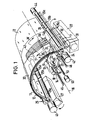
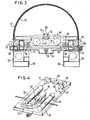
- the spatial arrangement of the embodiment according to FIGS. 3 and 4 is, however, made somewhat differently in order to achieve the desired scanning or exposure over a circumferential angle of 180 °.
- the circular segment-like holder 12 extends over a little more than 180 ° so that the web to be exposed can be scanned over the desired angle of 180 °.
- the circular segment-like holder thus has the shape of a half cylinder, which has the great advantage that the plane of the encoder cassette 27 runs parallel to the plane of the slave cassette and a simple symmetrical structure of the transport mechanism is given, the input side of the cassette 27 of the guide 58 and the Insertion roller pair 25 and on the output side of the removal roller pair 26, which consists of the guide device 59 extending through the cutting device 31 and the slave cassette 28.
- the axisymmetric design enables the encoder and slave cassette to be changed as required, which, when a later online development system is arranged, has a mechanically simplified effect.
- the semi-cylindrical arrangement is also characterized by the fact that it represents a very compact design in terms of height and depth.
- a special arrangement is made on the slide to enable scanning through 180 °.
- This arrangement can be seen in FIG. 4.
- the laser beam 18 ′ generated by the laser 18 first passes through a gray filter 57 and is then deflected by 90 ° by a deflection element 19. The beam then passes through a modulator 20 and hits a deflection element 21 again. After another deflection by 90 ° on the deflection element 21, the laser beam passes through a correction object tiv or a collimator 22 and then strikes a prism 23 '.
- This prism is tilted in its plane with respect to the slide, so that after two reflections on the inclined side surfaces of the prism, the laser beam strikes the rotating mirror arrangement 15 in a direction that coincides with the axis 16 of the circular segment-like holder 12.
- the rotating mirror arrangement has a rotating mirror 15 'with a flat mirror surface which forms an angle of 45 ° to the axis 16 of the segment-like holder 12.
- the tilted arrangement of the prism 23 ensures that the height of the laser beam 18' above the carriage 24 is increased, so that it is arranged in the direction of the axis of rotation 16 of the rotating mirror 15 'which is higher than the embodiment according to FIGS. 1 and 2. falls on it, the axis of rotation 16 being above the parts laterally adjacent on the slide, ie the laser 18 and the collimator 22.
- the device according to the invention both with individual sheets of the photosensitive sheet material and with webs thereof, e.g. Roll film can work.
Landscapes
- Engineering & Computer Science (AREA)
- Multimedia (AREA)
- Signal Processing (AREA)
- Laser Beam Printer (AREA)
Applications Claiming Priority (2)
| Application Number | Priority Date | Filing Date | Title |
|---|---|---|---|
| DE19833318311 DE3318311A1 (de) | 1983-05-19 | 1983-05-19 | Optische lichtfleck-abtastvorrichtung fuer ein photoempfindliches bahnmaterial bei optischen photosetzgeraeten |
| DE3318311 | 1983-05-19 |
Publications (3)
| Publication Number | Publication Date |
|---|---|
| EP0126469A2 true EP0126469A2 (fr) | 1984-11-28 |
| EP0126469A3 EP0126469A3 (en) | 1986-12-03 |
| EP0126469B1 EP0126469B1 (fr) | 1990-03-14 |
Family
ID=6199428
Family Applications (1)
| Application Number | Title | Priority Date | Filing Date |
|---|---|---|---|
| EP84105717A Expired - Lifetime EP0126469B1 (fr) | 1983-05-19 | 1984-05-18 | Dispositif de balayage par spot lumineux pour un matériau photosensible en bande dans les appareils de photocomposition optique |
Country Status (3)
| Country | Link |
|---|---|
| US (1) | US4595957A (fr) |
| EP (1) | EP0126469B1 (fr) |
| DE (2) | DE3318311A1 (fr) |
Cited By (15)
| Publication number | Priority date | Publication date | Assignee | Title |
|---|---|---|---|---|
| EP0217136A3 (en) * | 1985-09-03 | 1989-06-14 | Scangraphic Dr. Boger Gmbh | Photocomposition apparatus |
| WO1992014609A1 (fr) * | 1991-02-22 | 1992-09-03 | Purup Prepress A/S | Positionneur d'image laser |
| DE4124004A1 (de) * | 1991-07-19 | 1993-01-21 | Hell Ag Linotype | Vorrichtung zum auf- und abspannen von filmmaterial und betriebsweise der vorrichtung |
| EP0530683A3 (en) * | 1991-09-04 | 1993-04-21 | Dainippon Screen Mfg. Co., Ltd. | Apparatus for scanning drum inner face and method of scanning therefor |
| EP0571060A1 (fr) * | 1992-05-21 | 1993-11-24 | Scangraphic PrePress Technology GmbH | Procédé et dispositif pour l'exposition de la matière photosensible à la lumière |
| DE4238204C1 (de) * | 1992-11-09 | 1994-03-10 | Mannesmann Ag | Gehäuse für ein Fotosetzgerät |
| EP0571149A3 (fr) * | 1992-05-22 | 1994-12-21 | Chelgraph Ltd | Appareil de composition d'images. |
| EP0633543A1 (fr) * | 1993-07-05 | 1995-01-11 | Scitex Corporation Ltd. | Ordinatograghe avec planche à imprimer avec tambour à enregistrement intérieur |
| EP0708048A1 (fr) * | 1994-09-21 | 1996-04-24 | Bayer Corporation | Méthode et appareil pour installer une cassette d'alimentation de supports dans un compositeur d'image |
| FR2731650A1 (fr) * | 1995-03-13 | 1996-09-20 | Gerber Systems Corp | Procede de fabrication d'un pluralite de plaques d'inpression |
| EP0722243A3 (fr) * | 1995-01-11 | 1996-11-13 | Eastman Kodak Co | Imprimeur numérique avec patin de support avec élément de guidage de médias translatables dans celui-ci |
| WO1997009651A3 (fr) * | 1995-09-07 | 1997-04-03 | Hell Ag Linotype | Deflecteur de rayon lumineux |
| EP0805584A3 (fr) * | 1996-04-30 | 1998-04-01 | Bayer Corporation | Composeur d'image à tambour interne virtuel entraíné par cabestan |
| EP0729263A3 (fr) * | 1995-02-21 | 1998-09-16 | Bayer Corporation | Procédé et appareil pour maintenir le contact entre les moyens d'enregistrement et la surface de support des moyens dans un système de balayage |
| EP0989735A1 (fr) * | 1998-09-22 | 2000-03-29 | Fujifilm Electronic Imaging Limited | Appareil de balayage d'image |
Families Citing this family (27)
| Publication number | Priority date | Publication date | Assignee | Title |
|---|---|---|---|---|
| DE3564168D1 (en) * | 1984-05-29 | 1988-09-08 | Siemens Ag | Device for reading and/or for printing on record carriers |
| JPS6292572A (ja) * | 1985-10-17 | 1987-04-28 | Fuji Photo Film Co Ltd | 光ビ−ム走査装置 |
| US4963896A (en) * | 1988-04-28 | 1990-10-16 | Minolta Camera Kabushiki Kaisha | Recording media transporting device with arcshaped path |
| US5026133A (en) * | 1990-05-01 | 1991-06-25 | Torii Winding Machine Co., Ltd. | Large format laser scanner with wavelength insensitive scanning mechanism |
| DE4128468C2 (de) * | 1991-08-28 | 1997-05-28 | Hell Ag Linotype | Vorrichtung zur Teilung eines Lichtstrahls |
| DE4128469C2 (de) * | 1991-08-28 | 1997-12-18 | Hell Ag Linotype | Strahlteiler-Vorrichtung |
| DE4204340A1 (de) * | 1992-02-11 | 1993-08-12 | Mannesmann Ag | Aufnahmekassette fuer bahnmaterial, insbesondere fuer eine belichtete filmbahn |
| US5291392A (en) * | 1992-02-19 | 1994-03-01 | Gerber Systems Corporation | Method and apparatus for enhancing the accuracy of scanner systems |
| DE4235222C1 (de) * | 1992-10-13 | 1994-01-27 | Mannesmann Ag | Spiegelkopf für ein Fotosetzgerät |
| DE4244628C1 (de) * | 1992-12-29 | 1993-12-09 | Mannesmann Ag | Regelkreis-Einrichtung für Fotosetzgeräte |
| DE4313674C1 (de) * | 1993-04-22 | 1994-05-26 | Mannesmann Ag | Lichtsetzgerät |
| DE4313675C1 (de) * | 1993-04-22 | 1994-05-26 | Mannesmann Ag | Lichtsetzgerät |
| DE4344493C2 (de) * | 1993-12-24 | 1997-03-20 | Kodak Ag | Innentrommeldrucker mit einem Druckkopf zum Drucken auf ein Papier |
| US5436695A (en) * | 1994-03-17 | 1995-07-25 | Minnesota Mining And Manufacturing | Method and apparatus for loading thin film media |
| CA2146052A1 (fr) * | 1994-04-07 | 1995-10-08 | Mervin Leon Gangstead | Systeme de balayage optique |
| US5751334A (en) * | 1995-01-11 | 1998-05-12 | Eastman Kodak Company | Printer with support shoe and media metering therein |
| US5835686A (en) * | 1996-04-30 | 1998-11-10 | Agfa Division--Bayer Corporation | Electronic prepress system having a capstan driven virtual internal drum imagesetter |
| US5850248A (en) * | 1996-04-30 | 1998-12-15 | Agfa Division - Bayer Corporation | Capstan driven virtual internal drum imagesetter |
| USRE37376E1 (en) * | 1996-08-16 | 2001-09-18 | Creo Products Inc. | Method for rapid imaging of thermographic materials by extending exposure time in a single beam laser scanner |
| US6072518A (en) * | 1997-05-21 | 2000-06-06 | Creo Products Inc. | Method for rapid imaging of thermographic materials by extending exposure time in a single beam laser scanner |
| US5912458A (en) * | 1997-04-18 | 1999-06-15 | Gerber Systems Corporation | Multiple beam scanning system for an imaging device |
| US5910651A (en) * | 1997-07-15 | 1999-06-08 | Gerber Systems Corporation | Method and apparatus for image nonlinearity compensation in scanning systems |
| IL122269A (en) * | 1997-11-20 | 2001-03-19 | Digident Ltd | Scanning apparatus |
| US6624438B2 (en) | 1997-11-20 | 2003-09-23 | Orex Computed Radiography Ltd. | Scanning apparatus |
| US6396042B1 (en) | 1999-10-19 | 2002-05-28 | Raytheon Company | Digital laser image recorder including delay lines |
| US7354519B1 (en) | 2003-02-03 | 2008-04-08 | Hutchinson Technology Incorporated | Method and apparatus for fabricating a stent |
| US7225737B2 (en) * | 2003-12-09 | 2007-06-05 | Kodak Graphic Communications Canada Company | Method for automated platemaking |
Family Cites Families (13)
| Publication number | Priority date | Publication date | Assignee | Title |
|---|---|---|---|---|
| US2394649A (en) * | 1942-04-29 | 1946-02-12 | Rca Corp | Scanning apparatus |
| US2532799A (en) * | 1944-08-01 | 1950-12-05 | Rca Corp | Facsimile system having rotating scanner moving longitudinally within stationary transparent drum |
| US3588335A (en) * | 1968-09-11 | 1971-06-28 | Xerox Corp | Facsimile transceiver apparatus |
| US3610824A (en) * | 1968-09-11 | 1971-10-05 | Xerox Corp | Facsimile scanning apparatus |
| BE790892A (fr) * | 1971-11-03 | 1973-03-01 | Vickers Ltd | |
| BE795719A (fr) * | 1972-02-23 | 1973-06-18 | Vickers Ltd | Inscription de matiere en forme de feuille flexible |
| GB1382124A (en) * | 1972-05-19 | 1975-01-29 | Crosfield Electronics Ltd | Scanners for image reproduction |
| US3816659A (en) * | 1972-10-13 | 1974-06-11 | Perkin Elmer Corp | Scanning apparatus |
| US4131916A (en) * | 1975-12-31 | 1978-12-26 | Logetronics, Inc. | Pneumatically actuated image scanning reader/writer |
| FR2402982A1 (fr) * | 1977-09-09 | 1979-04-06 | Thomson Csf | Dispositif d'analyse opto-electronique de document, et systeme de transmission par fac-simile utilisant un tel dispositif |
| US4168506A (en) * | 1977-09-12 | 1979-09-18 | Rca Corporation | Film guide for optical scanners |
| US4257053A (en) * | 1979-02-09 | 1981-03-17 | Geosource, Inc. | High-resolution laser plotter |
| JPS5717918A (en) * | 1980-07-07 | 1982-01-29 | Dainippon Screen Mfg Co Ltd | Method and apparatus for scanning of light beam |
-
1983
- 1983-05-19 DE DE19833318311 patent/DE3318311A1/de active Granted
-
1984
- 1984-05-15 US US06/610,442 patent/US4595957A/en not_active Expired - Fee Related
- 1984-05-18 EP EP84105717A patent/EP0126469B1/fr not_active Expired - Lifetime
- 1984-05-18 DE DE8484105717T patent/DE3481594D1/de not_active Expired - Lifetime
Cited By (23)
| Publication number | Priority date | Publication date | Assignee | Title |
|---|---|---|---|---|
| EP0217136A3 (en) * | 1985-09-03 | 1989-06-14 | Scangraphic Dr. Boger Gmbh | Photocomposition apparatus |
| WO1992014609A1 (fr) * | 1991-02-22 | 1992-09-03 | Purup Prepress A/S | Positionneur d'image laser |
| US5459505A (en) * | 1991-02-22 | 1995-10-17 | Purup Prepress A/S | Laser image setter |
| DE4124004A1 (de) * | 1991-07-19 | 1993-01-21 | Hell Ag Linotype | Vorrichtung zum auf- und abspannen von filmmaterial und betriebsweise der vorrichtung |
| WO1993001936A1 (fr) * | 1991-07-19 | 1993-02-04 | Linotype-Hell Ag | Dispositif de serrage et de desserrage de materiau sous forme de film et son mode d'exploitation |
| US5500656A (en) * | 1991-07-19 | 1996-03-19 | Linotype-Hell Ag | Device for clamping and releasing film material and operation of said device |
| US5402155A (en) * | 1991-09-04 | 1995-03-28 | Dainippon Screen Mfg. Co., Ltd. | Apparatus for scanning drum inner face and method of scanning therefor |
| EP0530683A3 (en) * | 1991-09-04 | 1993-04-21 | Dainippon Screen Mfg. Co., Ltd. | Apparatus for scanning drum inner face and method of scanning therefor |
| EP0571060A1 (fr) * | 1992-05-21 | 1993-11-24 | Scangraphic PrePress Technology GmbH | Procédé et dispositif pour l'exposition de la matière photosensible à la lumière |
| US5488406A (en) * | 1992-05-21 | 1996-01-30 | Scangraphic Prepress Technology Gmbh | Method and apparatus for the exposing of light-sensitive material to be exposed |
| EP0571149A3 (fr) * | 1992-05-22 | 1994-12-21 | Chelgraph Ltd | Appareil de composition d'images. |
| DE4238204C1 (de) * | 1992-11-09 | 1994-03-10 | Mannesmann Ag | Gehäuse für ein Fotosetzgerät |
| US5488906A (en) * | 1993-07-05 | 1996-02-06 | Scitex Corporation Ltd. | Internal drum printing plate plotter |
| EP0633543A1 (fr) * | 1993-07-05 | 1995-01-11 | Scitex Corporation Ltd. | Ordinatograghe avec planche à imprimer avec tambour à enregistrement intérieur |
| EP0708048A1 (fr) * | 1994-09-21 | 1996-04-24 | Bayer Corporation | Méthode et appareil pour installer une cassette d'alimentation de supports dans un compositeur d'image |
| EP0722243A3 (fr) * | 1995-01-11 | 1996-11-13 | Eastman Kodak Co | Imprimeur numérique avec patin de support avec élément de guidage de médias translatables dans celui-ci |
| EP0729263A3 (fr) * | 1995-02-21 | 1998-09-16 | Bayer Corporation | Procédé et appareil pour maintenir le contact entre les moyens d'enregistrement et la surface de support des moyens dans un système de balayage |
| FR2731650A1 (fr) * | 1995-03-13 | 1996-09-20 | Gerber Systems Corp | Procede de fabrication d'un pluralite de plaques d'inpression |
| US5661566A (en) * | 1995-03-13 | 1997-08-26 | Gerber Systems Corporation | Method for making a plurality of printing plates |
| WO1997009651A3 (fr) * | 1995-09-07 | 1997-04-03 | Hell Ag Linotype | Deflecteur de rayon lumineux |
| EP0805584A3 (fr) * | 1996-04-30 | 1998-04-01 | Bayer Corporation | Composeur d'image à tambour interne virtuel entraíné par cabestan |
| EP0989735A1 (fr) * | 1998-09-22 | 2000-03-29 | Fujifilm Electronic Imaging Limited | Appareil de balayage d'image |
| US6600549B1 (en) | 1998-09-22 | 2003-07-29 | Fujifilm Electronic Imaging Ltd. | Image scanning apparatus |
Also Published As
| Publication number | Publication date |
|---|---|
| US4595957A (en) | 1986-06-17 |
| EP0126469A3 (en) | 1986-12-03 |
| DE3318311A1 (de) | 1984-11-22 |
| DE3318311C2 (fr) | 1988-06-23 |
| EP0126469B1 (fr) | 1990-03-14 |
| DE3481594D1 (de) | 1990-04-19 |
Similar Documents
| Publication | Publication Date | Title |
|---|---|---|
| EP0126469A2 (fr) | Dispositif de balayage par spot lumineux pour un matériau photosensible en bande dans les appareils de photocomposition optique | |
| DE2630135C3 (de) | Vorrichtung zum Herstellen von Röntgenschichtaufnahmen gekrümmter Flächen | |
| EP0217136B1 (fr) | Appareil de photocomposition | |
| DE2801112C2 (de) | Vorrichtung zum streifenweisen Abtasten einer Vorlage durch einen Abtaststrahl in einem Projektions-Kopiergerät | |
| DE1955294B2 (de) | Vorrichtung zum Herstellen eines panoramaartigen Röntgenbildes einer bogenförmigen Ebene eines Lebewesens, insbesondere des Zahnbogens | |
| DE2626917A1 (de) | Fotokopiergeraet | |
| DE3404799C2 (fr) | ||
| DE3539519C2 (fr) | ||
| DE3241574C2 (fr) | ||
| DE4317918C2 (de) | Bildabzugsvorrichtung | |
| DE4344493A1 (de) | Innentrommeldrucker mit Papiereinzugsvorrichtung | |
| DE3048322A1 (de) | Vorrichtung zum transportieren und fuehren eines bandfoermigen fotografischen aufzeichnungstraegers in einer fotosetzmaschine | |
| DE2446736B2 (de) | Elektrostatisches kopiergeraet | |
| DE1919108A1 (de) | Optisches System | |
| DE69623685T2 (de) | Verfahren und Apparat zum Zuführen eines abgetasteten Aufzeichnungsträgers | |
| DE3333770C2 (de) | Verstelleinrichtung für die Umlenkspiegel eines Kopiergerätes mit variabler Vergrößerung | |
| DE2820713C2 (de) | Projektionskopiervorrichtung mit unterschiedlicher Vorlagenabtastung bei Einzelblättern und bei Büchern | |
| DE68926327T2 (de) | Bildaufnahmegerät | |
| DE1056469B (de) | Durchlauf-Belichtungsgeraet zum Herstellen von Fotokopien von flachen Vorlagen | |
| DE69314043T2 (de) | Zufuehrvorrichtung einer maschine, versehen mit einer spindel mit abnehmbaren bandabgabekassetten, durch eine externe quelle | |
| DE69613491T2 (de) | Digitaldrucker mit Stützschuh mit darin liegendem Führungselement für verschiebbare Medien | |
| DE2421858C3 (de) | Kombinierte Faksimile-Bildabtast- und Bildaufzeichnungsvorrichtung | |
| DE69023066T2 (de) | Bildabtastgerät. | |
| DE3725697A1 (de) | Laserscangeraet | |
| DE2526906C3 (de) | Lichtsetzmaschine für Text- und Auszeichnungsschrift |
Legal Events
| Date | Code | Title | Description |
|---|---|---|---|
| PUAI | Public reference made under article 153(3) epc to a published international application that has entered the european phase |
Free format text: ORIGINAL CODE: 0009012 |
|
| AK | Designated contracting states |
Designated state(s): BE CH DE FR GB IT LI LU NL SE |
|
| PUAL | Search report despatched |
Free format text: ORIGINAL CODE: 0009013 |
|
| AK | Designated contracting states |
Kind code of ref document: A3 Designated state(s): BE CH DE FR GB IT LI LU NL SE |
|
| 17P | Request for examination filed |
Effective date: 19870527 |
|
| 17Q | First examination report despatched |
Effective date: 19881031 |
|
| GRAA | (expected) grant |
Free format text: ORIGINAL CODE: 0009210 |
|
| AK | Designated contracting states |
Kind code of ref document: B1 Designated state(s): BE CH DE FR GB IT LI LU NL SE |
|
| PG25 | Lapsed in a contracting state [announced via postgrant information from national office to epo] |
Ref country code: NL Effective date: 19900314 Ref country code: IT Free format text: LAPSE BECAUSE OF FAILURE TO SUBMIT A TRANSLATION OF THE DESCRIPTION OR TO PAY THE FEE WITHIN THE PRESCRIBED TIME-LIMIT;WARNING: LAPSES OF ITALIAN PATENTS WITH EFFECTIVE DATE BEFORE 2007 MAY HAVE OCCURRED AT ANY TIME BEFORE 2007. THE CORRECT EFFECTIVE DATE MAY BE DIFFERENT FROM THE ONE RECORDED. Effective date: 19900314 Ref country code: BE Effective date: 19900314 |
|
| REF | Corresponds to: |
Ref document number: 3481594 Country of ref document: DE Date of ref document: 19900419 |
|
| GBT | Gb: translation of ep patent filed (gb section 77(6)(a)/1977) | ||
| ET | Fr: translation filed | ||
| NLV1 | Nl: lapsed or annulled due to failure to fulfill the requirements of art. 29p and 29m of the patents act | ||
| PG25 | Lapsed in a contracting state [announced via postgrant information from national office to epo] |
Ref country code: LU Free format text: LAPSE BECAUSE OF REVOCATION BY EPO Effective date: 19901031 |
|
| PLBI | Opposition filed |
Free format text: ORIGINAL CODE: 0009260 |
|
| 26 | Opposition filed |
Opponent name: DR.-ING. RUDOLF HELL GMBH Effective date: 19901212 |
|
| RAP2 | Party data changed (patent owner data changed or rights of a patent transferred) |
Owner name: MANNESMANN SCANGRAPHIC GMBH |
|
| PLAB | Opposition data, opponent's data or that of the opponent's representative modified |
Free format text: ORIGINAL CODE: 0009299OPPO |
|
| R26 | Opposition filed (corrected) |
Opponent name: LINOTYPE-HELL AG Effective date: 19901212 |
|
| PGFP | Annual fee paid to national office [announced via postgrant information from national office to epo] |
Ref country code: DE Payment date: 19930623 Year of fee payment: 10 |
|
| PGFP | Annual fee paid to national office [announced via postgrant information from national office to epo] |
Ref country code: FR Payment date: 19940420 Year of fee payment: 11 Ref country code: CH Payment date: 19940420 Year of fee payment: 11 |
|
| PGFP | Annual fee paid to national office [announced via postgrant information from national office to epo] |
Ref country code: GB Payment date: 19940421 Year of fee payment: 11 |
|
| PGFP | Annual fee paid to national office [announced via postgrant information from national office to epo] |
Ref country code: SE Payment date: 19940425 Year of fee payment: 11 |
|
| RDAC | Information related to revocation of patent modified |
Free format text: ORIGINAL CODE: 0009299REVO |
|
| RDAG | Patent revoked |
Free format text: ORIGINAL CODE: 0009271 |
|
| STAA | Information on the status of an ep patent application or granted ep patent |
Free format text: STATUS: PATENT REVOKED |
|
| 27W | Patent revoked |
Effective date: 19940525 |
|
| GBPR | Gb: patent revoked under art. 102 of the ep convention designating the uk as contracting state |
Free format text: 940525 |
|
| R27W | Patent revoked (corrected) |
Effective date: 19940525 |
|
| REG | Reference to a national code |
Ref country code: CH Ref legal event code: PL |
|
| EUG | Se: european patent has lapsed |
Ref document number: 84105717.7 Effective date: 19940831 |
|
| APAH | Appeal reference modified |
Free format text: ORIGINAL CODE: EPIDOSCREFNO |