EP0126585A2 - Mit einem elektrischen Zündsystem versehene pyrotechnische oder explosive Ladung - Google Patents
Mit einem elektrischen Zündsystem versehene pyrotechnische oder explosive Ladung Download PDFInfo
- Publication number
- EP0126585A2 EP0126585A2 EP84303116A EP84303116A EP0126585A2 EP 0126585 A2 EP0126585 A2 EP 0126585A2 EP 84303116 A EP84303116 A EP 84303116A EP 84303116 A EP84303116 A EP 84303116A EP 0126585 A2 EP0126585 A2 EP 0126585A2
- Authority
- EP
- European Patent Office
- Prior art keywords
- pyrotechnic
- delay
- electrical
- charge
- circuit
- Prior art date
- Legal status (The legal status is an assumption and is not a legal conclusion. Google has not performed a legal analysis and makes no representation as to the accuracy of the status listed.)
- Granted
Links
- 239000002360 explosive Substances 0.000 title claims abstract description 9
- 238000010304 firing Methods 0.000 claims abstract description 15
- 239000003990 capacitor Substances 0.000 description 3
- 239000000779 smoke Substances 0.000 description 3
- 230000000977 initiatory effect Effects 0.000 description 2
- 230000007246 mechanism Effects 0.000 description 2
- 239000000203 mixture Substances 0.000 description 2
- 235000015842 Hesperis Nutrition 0.000 description 1
- 235000012633 Iberis amara Nutrition 0.000 description 1
- XAGFODPZIPBFFR-UHFFFAOYSA-N aluminium Chemical compound [Al] XAGFODPZIPBFFR-UHFFFAOYSA-N 0.000 description 1
- 229910052782 aluminium Inorganic materials 0.000 description 1
- 239000004411 aluminium Substances 0.000 description 1
- 239000011324 bead Substances 0.000 description 1
- 230000005540 biological transmission Effects 0.000 description 1
- 238000013016 damping Methods 0.000 description 1
- 238000005474 detonation Methods 0.000 description 1
- 238000010586 diagram Methods 0.000 description 1
- 230000005670 electromagnetic radiation Effects 0.000 description 1
- 239000002085 irritant Substances 0.000 description 1
- 231100000021 irritant Toxicity 0.000 description 1
- 239000000463 material Substances 0.000 description 1
- 238000009527 percussion Methods 0.000 description 1
- 229920003023 plastic Polymers 0.000 description 1
- 239000004033 plastic Substances 0.000 description 1
- 238000012216 screening Methods 0.000 description 1
- 239000007787 solid Substances 0.000 description 1
- 229910052715 tantalum Inorganic materials 0.000 description 1
- GUVRBAGPIYLISA-UHFFFAOYSA-N tantalum atom Chemical compound [Ta] GUVRBAGPIYLISA-UHFFFAOYSA-N 0.000 description 1
Images


Classifications
-
- F—MECHANICAL ENGINEERING; LIGHTING; HEATING; WEAPONS; BLASTING
- F42—AMMUNITION; BLASTING
- F42C—AMMUNITION FUZES; ARMING OR SAFETY MEANS THEREFOR
- F42C11/00—Electric fuzes
- F42C11/06—Electric fuzes with time delay by electric circuitry
-
- F—MECHANICAL ENGINEERING; LIGHTING; HEATING; WEAPONS; BLASTING
- F42—AMMUNITION; BLASTING
- F42C—AMMUNITION FUZES; ARMING OR SAFETY MEANS THEREFOR
- F42C11/00—Electric fuzes
- F42C11/001—Electric circuits for fuzes characterised by the ammunition class or type
- F42C11/003—Electric circuits for fuzes characterised by the ammunition class or type for hand grenades
-
- F—MECHANICAL ENGINEERING; LIGHTING; HEATING; WEAPONS; BLASTING
- F42—AMMUNITION; BLASTING
- F42C—AMMUNITION FUZES; ARMING OR SAFETY MEANS THEREFOR
- F42C14/00—Mechanical fuzes characterised by the ammunition class or type
- F42C14/02—Mechanical fuzes characterised by the ammunition class or type for hand grenades
- F42C14/025—Mechanical fuzes characterised by the ammunition class or type for hand grenades having electric igniters
-
- F—MECHANICAL ENGINEERING; LIGHTING; HEATING; WEAPONS; BLASTING
- F42—AMMUNITION; BLASTING
- F42C—AMMUNITION FUZES; ARMING OR SAFETY MEANS THEREFOR
- F42C9/00—Time fuzes; Combined time and percussion or pressure-actuated fuzes; Fuzes for timed self-destruction of ammunition
- F42C9/14—Double fuzes; Multiple fuzes
Definitions
- This invention relates to a pyrotechnic or explosive device and is especially, but not exclusively, applicable to a hand-propelled device such as a hand grenade.
- a wide range of pyrotechnic and explosive devices including smoke signals, flares, smoke screening grenades, irritant smoke and gas grenades and illuminating rockets, is used by military personnel. Many of these are required to be used in conditions where the noise produced by operating the initiating mechanism is disadvantageous or even dangerous.
- the "fly-off" handle of a hand grenade, percussion caps and spring-loaded trigger mechanisms all produce distinctive noises which could give a warning to an adversary or even indicate the position of the person projecting the device.
- the present invention provides a pyrotechnic or explosive device comprising a pyrotechnic or explosive charge and an electrical firing circuit therefor, the circuit including a source of electrical energy, for example an electric cell or battery, an electrical firing element to ignite the charge, and a hand-operable electric switch connected between the energy source and the firing element.
- a source of electrical energy for example an electric cell or battery
- an electrical firing element to ignite the charge
- a hand-operable electric switch connected between the energy source and the firing element.
- the firing element may simply comprise an electric igniter, the circuit then preferably including a delay element, for example a timing circuit, to operate the igniter at a predetermined delay after operation of the switch.
- the timing circuit may include an adjustable element whereby the delay may be varied by the user according, for example, to the range of projection of the device.
- a pyrotechnic delay can be incorporated in the charge, initiated by the firing element.
- the switch is preferably operatively coupled to a spring-biased handle, release of which closes the switch to initiate firing of the charge.
- the handle may be locked into a safe position in the manner conventional for hand-thrown grenades using a pin which has to be removed before the handle can be released to fire the charge.
- the grenade comprises a body 2 in the form of a can, e.g. of aluminium, into the open end of which is fitted a head-piece 4 containing the electrical timing and initiation system.
- the body 2 contains a charge 6 of a pyrotechnic composition into which exends an electric fuzehead 8 (e.g. type K fuzehead manufactured by ICI (Nobel) Ltd), which can ignite the charge when activated electrically.
- the fuzehead 8 extends from the head-piece 4, which is sealed in the end of the body 2 by a resilient O-ring 10.
- the can 2 is held on to the head-piece 4 by pressing the upper rim of the can into a circumferential groove 12 in the head-piece.
- the head-piece 4 has pivotally mounted thereon an operating handle or lever 14 which, in the "safe” position, lies along the body 2.
- the lever 14 is held in the "safe” position by means of a safety pin 16 which passes through the head-piece 4 and through a hole in a side flange of the lever 14 within the head-piece.
- the head-piece 4 contains a pair of electric cells 18, connected in series and sealed into a solid plastics composition.
- Wires 20 ( Figures 4 and 5) connect the cells 18 to two spaced terminals 22 mounted in a slidable block 24.
- the block 24 is held so that the terminals 22 are spaced from two corresponding terminal posts 26 fixed in the head-piece, by a camming plug 28, and springs 30 are provided to bias the block 24 into engagement with the plug 28.
- the plug 28 is spring-biased upwardly in the head-piece 4 by a spring 32 which locates within a socket 29 in the plug 28 and bears against a circuit board 34 which serves to close the lower face of the head-piece 4.
- the plug 28 is restrained by the lever 14 against upward movement, and also has an arm 27 which curves back to form a loop through which the pin 16 can pass, further ensuring that no movement can occur until the grenade is armed by removal of the pin.
- the grenade In use, the grenade is armed by removal of the pin 16, but is kept safe by holding the lever 14 engaged against the side of the body 2. On release of the lever, i.e. when the grenade has been thrown, the lever 14 is pivoted outwardly from the head-piece 4 and body 2 by the plug 28 which is in turn forced upwardly in the head-piece by the spring 32.
- the lower portion of the plug is tapered so as to allow the block 24 to slide as the plug 28 moves upwardly. This permits the terminals 22 to contact the corresponding terminal posts 26.
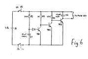
- terminal posts are each soldered to respective parts of the electrical control circuit provided on the circuit board 34, described in more detail hereinafter with reference to Figure 6, and so engagement of the terminals 22 with the terminal posts 26 completes the electrical connection from the cells 18 to the circuit, which ignites the pyrotechnic charge after an appropriate delay.
- Figure 5 shows the components in the position wherein ignition occurs.
- the grenade head-piece 4 is provided with an opposed pair of grooves 36 in the sides thereof whereby the grenade may be supported in a trip-stand permitting the grenade to be operated by a trip-wire or the like.
- the terminal posts 26 each have a socket 25 opening to the exterior of the head-piece 4, whereby wires may be connected between the circuit and a remote power source and switch for remotely igniting the device.
- Each wire can be provided with a pin conforming with a socket 25.
- the electric cell is suitably of a type retaining a charge for a long period of time, thereby giving the grenade a long "shelf-life" in which it remains usable when stored.
- the electrical circuit includes a first transistor TR1 connected across the two terminals of the circuit via resistor R2, the base potential of the transistor being controlled by a tantalum bead capacitor Cl charged by the cells 18 via resistor Rl when the circuit is closed by release of the lever 14, as hereinbefore described.
- the capacitor Cl and resistor Rl act as time delay elements, the transistor TR1 only becoming conductive when the capacity Cl has become charged to the required potential on the base of the transistor.
- fixed resistor Rl is replaced with a variable resistor controllable by an externally-accessible control, whereby the length of the time-delay before ignition may be preselected at the time of use of the device.
- any noise emitted by closure of the switch can be damped by surrounding the switch with sound-damping material, permitting the device to be operated substantially inaudibly.
Landscapes
- Engineering & Computer Science (AREA)
- General Engineering & Computer Science (AREA)
- Air Bags (AREA)
Applications Claiming Priority (2)
| Application Number | Priority Date | Filing Date | Title |
|---|---|---|---|
| GB8313572 | 1983-05-18 | ||
| GB8313572 | 1983-05-18 |
Publications (3)
| Publication Number | Publication Date |
|---|---|
| EP0126585A2 true EP0126585A2 (de) | 1984-11-28 |
| EP0126585A3 EP0126585A3 (en) | 1986-01-29 |
| EP0126585B1 EP0126585B1 (de) | 1989-01-04 |
Family
ID=10542863
Family Applications (1)
| Application Number | Title | Priority Date | Filing Date |
|---|---|---|---|
| EP84303116A Expired EP0126585B1 (de) | 1983-05-18 | 1984-05-09 | Mit einem elektrischen Zündsystem versehene pyrotechnische oder explosive Ladung |
Country Status (3)
| Country | Link |
|---|---|
| US (1) | US4617866A (de) |
| EP (1) | EP0126585B1 (de) |
| DE (1) | DE3475949D1 (de) |
Cited By (2)
| Publication number | Priority date | Publication date | Assignee | Title |
|---|---|---|---|---|
| GB2160954A (en) * | 1984-05-23 | 1986-01-02 | Plessey Co Plc | Mortars |
| EP0329042A3 (de) * | 1988-02-16 | 1991-08-14 | Alliant Techsystems Inc. | Handbetriebene Aktiviervorrichtung |
Families Citing this family (6)
| Publication number | Priority date | Publication date | Assignee | Title |
|---|---|---|---|---|
| US4856433A (en) * | 1987-07-13 | 1989-08-15 | Scot, Incorporated | Initiator device with adiabatic compression ignition |
| US4882993A (en) * | 1988-08-05 | 1989-11-28 | The United States Of America As Represented By The Secretary Of The Army | Electronic back-up safety mechanism for hand-emplaced land mines |
| US5435248A (en) * | 1991-07-09 | 1995-07-25 | The Ensign-Bickford Company | Extended range digital delay detonator |
| US5173569A (en) * | 1991-07-09 | 1992-12-22 | The Ensign-Bickford Company | Digital delay detonator |
| US6631667B1 (en) | 2000-10-25 | 2003-10-14 | Lockheed Martin Corporation | Explosive-bolt-activated spring-loaded actuation device |
| WO2011127391A2 (en) * | 2010-04-08 | 2011-10-13 | Bae Systems Information And Electronic Systems Integration Inc. | Technique for fully discharging a storage capacitor in a firing circuit for an electro-explosive device |
Family Cites Families (9)
| Publication number | Priority date | Publication date | Assignee | Title |
|---|---|---|---|---|
| FR1292384A (fr) * | 1961-03-24 | 1962-05-04 | Soc Tech De Rech Ind | Fusée électrique à contacteur par inertie |
| US3101055A (en) * | 1962-02-28 | 1963-08-20 | William K Kuntz | Disposable bomb arming device |
| DE1703991A1 (de) * | 1968-08-09 | 1972-02-17 | Dynamit Nobel Ag | Aufschlag- bzw.Erschuetterungszuender |
| US3636878A (en) * | 1969-08-06 | 1972-01-25 | James P Fay | Safety grenade |
| US3712218A (en) * | 1969-08-06 | 1973-01-23 | J Fay | Safety grenade |
| FR2116783A5 (de) * | 1970-12-09 | 1972-07-21 | Clausin Pierre | |
| US4041865A (en) * | 1975-06-04 | 1977-08-16 | Seth F. Evans | Method and apparatus for detonating explosives |
| CH595610A5 (de) * | 1976-01-23 | 1978-02-15 | Oerlikon Buehrle Ag | |
| FR2483068B1 (fr) * | 1980-05-21 | 1986-09-26 | Ruggieri Ets | Fusee electronique pour grenade a main ou a fusil |
-
1984
- 1984-05-09 DE DE8484303116T patent/DE3475949D1/de not_active Expired
- 1984-05-09 EP EP84303116A patent/EP0126585B1/de not_active Expired
- 1984-05-16 US US06/610,706 patent/US4617866A/en not_active Expired - Fee Related
Cited By (2)
| Publication number | Priority date | Publication date | Assignee | Title |
|---|---|---|---|---|
| GB2160954A (en) * | 1984-05-23 | 1986-01-02 | Plessey Co Plc | Mortars |
| EP0329042A3 (de) * | 1988-02-16 | 1991-08-14 | Alliant Techsystems Inc. | Handbetriebene Aktiviervorrichtung |
Also Published As
| Publication number | Publication date |
|---|---|
| EP0126585A3 (en) | 1986-01-29 |
| DE3475949D1 (en) | 1989-02-09 |
| US4617866A (en) | 1986-10-21 |
| EP0126585B1 (de) | 1989-01-04 |
Similar Documents
| Publication | Publication Date | Title |
|---|---|---|
| US3941058A (en) | Electric ignition device | |
| GB2178830B (en) | Detonator | |
| US4617866A (en) | Pyrotechnic or explosive device | |
| KR0182633B1 (ko) | 개량된 재래식 탄약용 자폭 퓨즈 | |
| GB1197347A (en) | A Fuze for an Explosive Device | |
| US4938144A (en) | Motion activated thermal fogger | |
| US4416631A (en) | Small arms firing effects simulator | |
| US2991716A (en) | Electrically operated fuze | |
| US1541790A (en) | Well-exploding device | |
| US3618522A (en) | Dual safety grenade fuze | |
| US4012671A (en) | Trigger circuit | |
| US4495848A (en) | Pyro-gun | |
| US3994049A (en) | Automatic harness release assembly | |
| US3641938A (en) | Percussion or vibration fuse for explosive charge | |
| US5396845A (en) | Modular fuze | |
| US3910190A (en) | Hand-held signaling device having manual firing means | |
| US4389940A (en) | Antipersonnel mine | |
| GB752153A (en) | Improvements in self-propelled projectiles | |
| US4374492A (en) | Antipersonnel mine | |
| US2042461A (en) | Fuse for candles and the like | |
| US3295449A (en) | Electrical fuses for projectile or the like | |
| US3636878A (en) | Safety grenade | |
| US3955507A (en) | Proximity fuse | |
| US4079395A (en) | Electronic flash attachment for cameras | |
| US3884151A (en) | Detonator for land mines |
Legal Events
| Date | Code | Title | Description |
|---|---|---|---|
| PUAI | Public reference made under article 153(3) epc to a published international application that has entered the european phase |
Free format text: ORIGINAL CODE: 0009012 |
|
| AK | Designated contracting states |
Designated state(s): DE FR GB |
|
| PUAL | Search report despatched |
Free format text: ORIGINAL CODE: 0009013 |
|
| AK | Designated contracting states |
Designated state(s): DE FR GB |
|
| 17P | Request for examination filed |
Effective date: 19860221 |
|
| 17Q | First examination report despatched |
Effective date: 19870424 |
|
| GRAA | (expected) grant |
Free format text: ORIGINAL CODE: 0009210 |
|
| AK | Designated contracting states |
Kind code of ref document: B1 Designated state(s): DE FR GB |
|
| REF | Corresponds to: |
Ref document number: 3475949 Country of ref document: DE Date of ref document: 19890209 |
|
| ET | Fr: translation filed | ||
| PLBE | No opposition filed within time limit |
Free format text: ORIGINAL CODE: 0009261 |
|
| STAA | Information on the status of an ep patent application or granted ep patent |
Free format text: STATUS: NO OPPOSITION FILED WITHIN TIME LIMIT |
|
| 26N | No opposition filed | ||
| PGFP | Annual fee paid to national office [announced via postgrant information from national office to epo] |
Ref country code: GB Payment date: 19940429 Year of fee payment: 11 |
|
| PGFP | Annual fee paid to national office [announced via postgrant information from national office to epo] |
Ref country code: FR Payment date: 19940511 Year of fee payment: 11 Ref country code: DE Payment date: 19940511 Year of fee payment: 11 |
|
| PG25 | Lapsed in a contracting state [announced via postgrant information from national office to epo] |
Ref country code: GB Effective date: 19950509 |
|
| GBPC | Gb: european patent ceased through non-payment of renewal fee |
Effective date: 19950509 |
|
| PG25 | Lapsed in a contracting state [announced via postgrant information from national office to epo] |
Ref country code: DE Effective date: 19960201 |
|
| PG25 | Lapsed in a contracting state [announced via postgrant information from national office to epo] |
Ref country code: FR Effective date: 19960229 |
|
| REG | Reference to a national code |
Ref country code: FR Ref legal event code: ST |
|
| REG | Reference to a national code |
Ref country code: FR Ref legal event code: ST |