EP0126714A2 - Procédé et appareil pour le traitement de solutions par osmose inverse - Google Patents
Procédé et appareil pour le traitement de solutions par osmose inverse Download PDFInfo
- Publication number
- EP0126714A2 EP0126714A2 EP84810237A EP84810237A EP0126714A2 EP 0126714 A2 EP0126714 A2 EP 0126714A2 EP 84810237 A EP84810237 A EP 84810237A EP 84810237 A EP84810237 A EP 84810237A EP 0126714 A2 EP0126714 A2 EP 0126714A2
- Authority
- EP
- European Patent Office
- Prior art keywords
- rinsing
- solute
- phase
- chamber
- solution
- Prior art date
- Legal status (The legal status is an assumption and is not a legal conclusion. Google has not performed a legal analysis and makes no representation as to the accuracy of the status listed.)
- Withdrawn
Links
Images


Classifications
-
- B—PERFORMING OPERATIONS; TRANSPORTING
- B01—PHYSICAL OR CHEMICAL PROCESSES OR APPARATUS IN GENERAL
- B01D—SEPARATION
- B01D61/00—Processes of separation using semi-permeable membranes, e.g. dialysis, osmosis or ultrafiltration; Apparatus, accessories or auxiliary operations specially adapted therefor
- B01D61/02—Reverse osmosis; Hyperfiltration ; Nanofiltration
- B01D61/08—Apparatus therefor
-
- B—PERFORMING OPERATIONS; TRANSPORTING
- B01—PHYSICAL OR CHEMICAL PROCESSES OR APPARATUS IN GENERAL
- B01D—SEPARATION
- B01D61/00—Processes of separation using semi-permeable membranes, e.g. dialysis, osmosis or ultrafiltration; Apparatus, accessories or auxiliary operations specially adapted therefor
- B01D61/02—Reverse osmosis; Hyperfiltration ; Nanofiltration
- B01D61/025—Reverse osmosis; Hyperfiltration
-
- B—PERFORMING OPERATIONS; TRANSPORTING
- B01—PHYSICAL OR CHEMICAL PROCESSES OR APPARATUS IN GENERAL
- B01D—SEPARATION
- B01D65/00—Accessories or auxiliary operations, in general, for separation processes or apparatus using semi-permeable membranes
- B01D65/02—Membrane cleaning or sterilisation ; Membrane regeneration
-
- B—PERFORMING OPERATIONS; TRANSPORTING
- B01—PHYSICAL OR CHEMICAL PROCESSES OR APPARATUS IN GENERAL
- B01D—SEPARATION
- B01D2313/00—Details relating to membrane modules or apparatus
- B01D2313/46—Supply, recovery or discharge mechanisms of washing members
-
- B—PERFORMING OPERATIONS; TRANSPORTING
- B01—PHYSICAL OR CHEMICAL PROCESSES OR APPARATUS IN GENERAL
- B01D—SEPARATION
- B01D2313/00—Details relating to membrane modules or apparatus
- B01D2313/48—Mechanisms for switching between regular separation operations and washing
-
- B—PERFORMING OPERATIONS; TRANSPORTING
- B01—PHYSICAL OR CHEMICAL PROCESSES OR APPARATUS IN GENERAL
- B01D—SEPARATION
- B01D2321/00—Details relating to membrane cleaning, regeneration, sterilization or to the prevention of fouling
- B01D2321/02—Forward flushing
-
- B—PERFORMING OPERATIONS; TRANSPORTING
- B01—PHYSICAL OR CHEMICAL PROCESSES OR APPARATUS IN GENERAL
- B01D—SEPARATION
- B01D2321/00—Details relating to membrane cleaning, regeneration, sterilization or to the prevention of fouling
- B01D2321/04—Backflushing
Definitions
- the invention relates to a method for separating a solute-containing solution, in particular without constant chemical pretreatment by means of counter osmosis into a solute-rich concentrate and a low-solute solvent, and above all to a treatment of interfering substances, such as precipitates and deposits of soluble substances from such solutions, and also to a Device for performing the method.
- Counter-osmosis is a separation process used worldwide, which enables a solute-containing liquid flow to be divided into low-solute solvent and a high-solids concentrate by the solvent being pressurized to a pressure that must be greater than the osmotic pressure of the system by means of a semipermeable solvent-permeable only Membrane is pressed.
- This process is widely used for the desalination of drinking water, brackish water and sea water as well as for a whole range of other solutions in various areas of research, industry and technology. As long as there are only slight traces of suspended matter in the liquid flow to be treated and the solubility of the solutes is not exceeded, this process is characterized by simplicity and economy.
- the crystallization of sparingly soluble substances first creates crystal nuclei, to which other ions or molecules attach themselves in an orderly manner. If the crystals become large enough, they interfere with the operation of the counter osmosis system. By adding suitable substances that have an affinity for crystal lattice sites, the growth of such crystals can be inhibited and temporarily prevented.
- suitable substances that prevent poorly soluble substances such as sulfates and carbonates of the alkaline earth metals from growing are inorganic polyphosphates, organophosphorus compounds, polycarboxylic acids, polysulfonic acids etc. Because the chemicals used are only used in very small amounts, in concentrations of 1 to 20 g / m3 in particular when the machine is at a standstill and certain interfering substances are present, the hardness stabilization is not ensured.
- the object of the invention is now to provide measures which are as simple as possible to implement with a method of the type mentioned at the outset, with which the precipitates and deposits occurring during a separation process due to counter-osmosis are treated in such a way that a long-term, trouble-free separation process can be ensured ; Furthermore, a structurally simple, functionally reliable and economically working device for carrying out such a method is to be created.
- the solution according to the invention in the method consists in allowing precipitation and deposition of soluble substances taking place during the separation process on the part of the solute-containing solution or the solute-rich concentrate during a process phase of a predetermined duration and that the precipitations and deposits then present in a rinsing phase a rinse with a rinsing solution is at least largely dissolved.
- the method according to the invention also takes advantage of the fact that freshly precipitated and deposited crystal nuclei, which are very small, have a very large surface area in relation to their volume, while in older deposits the surface area for rinsing has decreased considerably after a certain process time .
- the effects occurring in the process according to the invention can also be explained more specifically to the elements used in counter osmosis in such a way that precipitations occur during the process phase and settle on the membrane surface, but that the supersaturated solute-rich solution does not quantify all the excess salts but only in fractions separates, and that at the beginning of the rinsing, the active surface of the precipitate, as said, is so large in relation to the total volume that these precipitates can quickly dissolve in the rinsing solution. Since the counter-osmosis elements used for the method according to the invention meet known specifications, the duration of the process phase can be determined for each given element, taking into account features of the solution rich in solute, and the duration of the rinsing phase can accordingly be determined.
- the method according to the invention characterizes procedural measures for the separation of a solute-containing solution by means of counter osmosis into a solute-rich concentrate and a low-solute solvent, in particular without constant chemical pretreatment.
- Another procedural aspect is associated with this process complex, namely the treatment of interfering substances, such as the precipitation of soluble substances from solutions.
- the separation of a sol-containing solution also includes the treatment of raw water in the broadest sense
- the invention also relates to a process for the treatment of raw water, such as wastewater, brackish water, sea water and the like, for drinking water, reusable process water and the like by means of counter osmosis.
- the rinsing phase provided by the method according to the invention can be operated differently in relation to the process phase. You can in the ongoing separation be integrated into the process, for example by periodically switching on low solutol solvent and diluting the solutrich solution for the duration of the rinsing phase, so that dissolving states are set compared to the process phase. It would also be possible to interrupt the separation process for the duration of the rinsing phase and, if necessary, to displace the sol-containing solution or the solute-rich concentrate by the rinsing solution supplied.
- the direction of flow of the rinsing solution which exerts its dissolving effect on the semipermeable membrane, is determined with a flush that runs in the same flow direction as that of the sol-containing solution.
- a symmetrical, homogeneous membrane on the other hand, can be operated both in the direction of flow of the solute-rich solution and in countercurrent to it.
- additives such as hydrochloric acid, sulfuric acid, nitric acid, carbonic acid, sulfamic acid, citric acid, ascorbic acid, oxalic acid, sodium hydroxide, potassium hydroxide, ammonia, as sequestering agents and / or complexing agents, hexametaphosphates, tripolyphosphates, polyacrylates, can be used as additives for lowering or increasing the pH.
- Inorganic and organic acids and bases such as hydrochloric acid, sulfuric acid, nitric acid, carbonic acid, sulfamic acid, citric acid, ascorbic acid, oxalic acid, sodium hydroxide, potassium hydroxide, ammonia, as sequestering agents and / or complexing agents, hexametaphosphates, tripolyphosphates, polyacrylates, can be used as additives for lowering or increasing the pH.
- disinfectants and / or biostatics such as formaldehyde, sodium meta bisulfite, hydrogen peroxide, iodine, chlorine, bromine, chlorine dioxide, silver ions, copper ions
- film formers such as tannic acid, polyvinyl methyl ether and / or organic solvents such as alkanols, ketones,
- Another advantage of the invention is that the additives used for a short time can be added in much higher concentrations than is the case with conventional processes.
- Another advantage of the method according to the invention is that the dissolving power of the rinsing solution is increased 1-ann by subjecting it at least partially to ion exchange prior to its use is used for softening, decationation or desalination. If the rinsing solution is at least partially passed through an ion exchange resin bed loaded with protons, it can be regenerated with acid or electrolytically with a lower energy requirement during the working phase.
- the inventive method can thus in each region of the Ge g enosmose used technique, particularly when it comes to treat solutions of any current by the addition of stabilizing agents kind would unfavorably altered.
- a well water containing 6 val / m3 bicarbonate, 1 val / m3 chloride and sulfate as well as 4.5 val / m3 calcium and 0.5 val / m3 magnesium and 2 val / m3 sodium is to be desalinated with counter osmosis with a yield of 75%.
- the addition of 4.5 val / m3 hydrochloric acid or sulfuric acid is necessary for this task without the addition of additional stabilizing agents.
- Stabilisicrungsmittels this amount can be decreased by 1 from 5 to 25%.
- the water pretreated in this way and desalinated by means of counter osmosis still contains approx.
- Example 1 The well water mentioned in Example 1 is processed according to the invention without acid metering by the counter osmosis system. After an interval of 2 to 8 hours, an amount of acid corresponding to or greater than the amount of bicarbonate in the raw water is metered in for 2 to 20 minutes. This procedure enables the system to be operated free of calcium carbonate precipitations.
- Approx. 5% lactose solution from milk or whey preparation can be concentrated to counter-saturation by counter osmosis. If the saturation point is exceeded, part of the sugar can be crystallized in a targeted manner by cooling the concentrate. The mother solution in the counter osmosis system can be concentrated again by heating it again. Since work is always carried out close to the saturation limit, there is a risk of precipitation on the membrane. However, if the membrane is used for 5 to 5 hours after work phases Rinsed for up to 50 minutes with product water freed from lactose so that work can be carried out without serious contamination.
- Example 1 The well water described in Example 1 is processed completely without acid metering by means of counter osmosis by the process according to the invention.
- the pure water obtained in this way is now not fed directly to its consumption-based determination, but is fed directly to a counter osmosis system after the end of the process phase, without increasing the discharge-side pressure, or after an increase in pressure on the raw water or concentrate side, which initiates the rinsing phase.
- at least two counter-osmosis elements are evidently combined in such a way that a rinsing phase takes place in the other element during a process phase and vice versa.
- counter-osmosis systems such as at least one pressure vessel with a semi-permeable membrane dividing its interior to form a first chamber for a solute-containing solution or a concentrate of this solution and a second chamber for a solute-poor solvent, the membrane being permeable from the first to the second chamber, a conveyor connected to the first chamber for supplying solute-containing solution under a predetermined pressure and a concentrate drain leading out of this
- a flushing line arrangement which opens into the first chamber is now provided, by means of which the said flushing solution can be introduced into the first chamber from a flushing solution supply during the flushing phase; furthermore, a conveying and metering unit for metering the quantity and pressure of the flushing solution to be introduced is arranged in the flushing line arrangement, and a control and regulation arrangement is at least connected to the conveying and metering unit in order to relate the setting of the duration and, if appropriate, the interval of the flushing phase to carry out other procedures mentioned.
- a metered amount of a rinsing solution can be introduced for a certain time via the rinsing line arrangement, through the conveying device connected to the first chamber, with the process being continued, reduced or switched off, and thereby creating dissolving states on the membrane element.
- the control and regulating arrangement can switch the operation of the device in such a way that with the start of the rinsing phase via the concentrate drain or a separate control means-operated outlet line, a solution rich in solids is displaced from the first chamber.
- the low-solute pure water can be fed from the second chamber directly or after a pressure increase as a rinsing solution to the first chamber.
- the flushing line can be designed in such a way that, equipped with a delivery and metering unit, it bypasses the semipermeable membrane outside the pressure chamber, so that there is a connecting line between the two chambers, the flow rate and pressure of which via the control valve mentioned. and control arrangement is adjustable.
- a metering device for rinsing solution additives can be connected to the rinsing line, for example in order to introduce a rinsing solution enriched with additives into the first chamber during the rinsing phase after a series of rinses with low-solubility solvent without additives. After a longer period of use of the system, it may be necessary to switch off the separation process and to carry out cleaning with certain additives without a low-solvent solvent for one or more rinsing intervals. In such a case, the metering device connected to the flushing line can also be used. After such a cleaning treatment, it is advisable to remove the cleaning solution from the pressure vessel before starting the separation process again.
- the rinsing line surrounding the membrane can have such a capacity that it can hold an amount of rinsing solution which is approximately required for a rinsing phase.
- At least two pressure vessels are used, in which, according to the invention, the two first chambers are connected to a distributor line arrangement, and in which the outflow lines for low-solute solvent emerging from the second chambers into the first chambers of each other pressure vessels are introduced, so that there is a mutual series connection between the second chambers and the first chambers of the pressure vessels.
- Various delivery, metering and switching elements are provided in the distribution line arrangement and the drain lines, which in turn are connected to a control and regulating arrangement which switches over the process and flushing phases between the pressure vessels, so that for the duration of a process phase in a pressure vessel is set to a rinsing phase in the other pressure vessel and is then passed at least a portion of the recovered in the first-mentioned pressure vessel solutarmen solvent as a washing solution in the first chamber and fed to the rinsing of the 'proper usage determination.
- the low-solvent solvent from the second chamber can either be introduced directly into the corresponding second chamber without an increase in the solvent pressure for flushing, or the solvent can be raised to a suitable flushing solution pressure in this line via a corresponding pressure booster pump.
- This embodiment also includes the possibility of using only a portion of the low-solvent solvent obtained in the other pressure vessel for rinsing and the remaining portion to be used immediately. The slight salting occurring during the rinsing process and the dissolution of the said substances is practically negligible.
- a pressure vessel is used, the interior of which is subdivided by a symmetrical, homogeneous membrane, so as to form the two chambers, as described in the above variants.
- the rinsing solution can be conveyed through the membrane in both directions, and if, for example, after the process phase has been switched off, a rinsing in the counterflow direction takes place, a separate rinsing line, as in the variants described above, is not necessary, as long as it is sufficient, with the low-solids Solvent obtained during the process phase to carry out the rinsing process.
- a holding and conveying device is provided in the outflow line for low-solvent solvents, which interrupts the outflow of the solvent at the beginning of the rinsing phase and exerts a corresponding pressure on the solvent in the second chamber in order to be able to To convey countercurrent through the membrane and thereby let the rinsing process take place.
- the solute-rich solution still in the first chamber can be displaced either via the condensate drain or a separate drainage means.
- a symmetrical, homogeneous membrane in a pressure vessel also opens up the possibility of interconnecting a row. such pressure vessels.
- the process phase. In the respective pressure vessel can then be set so that the precipitations and deposits are permitted up to a predetermined limit value in the case of mutual operation between the two chambers, and then in a rinsing phase in which the low-solvent solvent likewise flows through the membrane in both directions to dissolve the precipitations and deposits.
- the device shown in FIG. 1 has a pressure vessel 1, which is divided on the inside by a semipermeable membrane 2 to form a first chamber 3 and a second chamber 4.
- the schematic representation of the membrane 2, as well as that of the entire device, does not reflect a structural design, but is only intended to make the functional principles clear.
- Those skilled in the field of counter-osmosis are familiar with the osmosis elements, often referred to as permeators, whose membranes can be designed as hollow fiber membranes, spiral wound membranes, etc.
- the first chamber 3 is used for the supply of solute-containing solution which, when passing through the membrane 2, is separated into a low-solute solvent that accumulates in the chamber 4 and a solute-rich concentrate, which is concentrated in the first chamber provided concentrate drain 6 can be discharged.
- the increased pressure in the chamber 3 required for the counter osmosis is generated by a conveyor 5 at the inlet end of the chamber.
- This conveyor is equipped with a pump and corresponding valve means.
- the low solut solvent can be discharged from the second chamber 4 via a drain line 7 for further treatment or directly for the intended use.
- a control and regulating arrangement 11 is connected to the conveying device 5, the concentrate drain 6 and the drain line 7 in order to carry out the switching and regulating processes required on these units, depending on the process sequence.
- a rinsing line arrangement 8 which has a rinsing solution supply 9, opens into the first chamber 3 as well as a conveying and metering unit 10 and serves to introduce a rinsing solution from the rinsing solution supply into the first chamber 3, for example at the beginning of the rinsing phase.
- This rinsing solution flows through the semipermeable membrane 2 in the direction indicated by the arrows, which corresponds to the direction in which the separation process takes place, and thereby dissolves any precipitations and deposits present in the first chamber 3 and in and on the membrane 2 by rinsing.
- the conveying and metering unit 10 is also connected to the control and regulating arrangement 11 and is actuated by the latter in accordance with the desired process sequence.
- this unit 10 can have a pump and valve means suitable for metering.
- a dosing pump could also perform both functions.
- a rinsing line arrangement 8 ' which comprises a conveying and metering unit 10', is arranged such that it bypasses the semipermeable membrane 2, the rinsing vessel .4! connects to the first chamber 3.
- the delivery and metering unit 10 ' With appropriate actuation of the delivery and metering unit 10 'by the control and regulating arrangement 11, low-solute solvent obtained during the process phase can be introduced from the rinsing chamber 4' for rinsing into the first chamber 3 and thus fed to the semipermeable membrane 2.
- the rinsing line arrangement 8 ' If it is desired to add additives to the low-solubility solvent in the rinsing line arrangement 8 ', this can be done continuously during the rinsing phase or at certain intervals, depending on the process sequence to be selected, via a metering device 12 which opens into the rinsing line arrangement 8'.
- the conveying and dosing unit 10 ' like the conveyor device 5 described in connection with FIG. 1, the concentrate drain 6 and the drain line 7 are connected to the control and regulating arrangement 11 and are controlled accordingly by the latter.
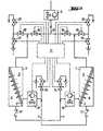
- FIG. 3 shows a device with two pressure vessels 1, 1 ', the first chambers 3, 3' of which are connected to a distributor line arrangement 14 and are charged with solute-containing solution via the conveyor device 5.
- the membranes .2, 2 ' are separated in the pressure vessels 1,1', the low-solvent solvent in the second chamber 4,4 'is fed through the respective drain line 7,7; each has a non-return valve 17,17' contains, led out of the pressure vessel and can then be introduced into the first chamber 3, 3 'in order to serve as a rinsing solution and to be supplied to the consumer via 18, 18' and 20, 20 '.
- a control and regulating arrangement 11 ' is provided for switching valves 16, 16' provided in the distribution line arrangement 14, further valve switching means 18, 18 ', 20, 20', the conveying device 5, the pressure-maintaining and shut-off device 15, 15 'and if necessary, to control or regulate a booster pump 19, 19 'and drain valves 13, 13' depending on the desired process sequence.
- the control and regulating arrangement 11 switches off the rinsing phase in the pressure vessel 1' and the process phase that the pressure vessel 1 is now rinsed via the line 7 'with the low-solvent solvent obtained in the second chamber 4'. becomes.
- the solvent which is still low in solute, flows through the line 7 and the pressure-maintaining and shut-off device 18, 20 for consumption.
- valve switching means 18, 18' and drain valve 13, 13 ' are provided in the distributor line arrangement, which release the displaced solute-rich Run solution to a drain.
- the flushing which takes place in a pressure vessel in each case can take place without increasing the pressure of the low-solubility solvent or with increased flushing solution pressure.
- 3 shows a booster pump 19, 19 'in the respective drain line 7, 7'. These pressure booster pumps are also controlled via the control and regulating arrangement 11.
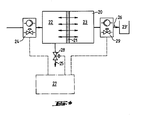
- a pressure vessel 20 is subdivided by a symmetrical homogeneous membrane 21 into a first chamber 22 for a solute-containing solution or a concentrate of this solution, as well as a second chamber 23 and a reservoir 23 for low solutine solvent.
- the double arrows indicate the passage directions of the membrane 21.
- no rinsing line is provided, but the rinsing is carried out by generating a countercurrent to the direction of flow in the process phase, low-solvent solvent being pressed through the membrane from the second chamber 23 and the rinsing process taking place in the process.
- a displacement of the solute-rich concentrate or the solute-containing solution located in the first chamber 22 at the end of the process phase can be derived by actuating a switching element 28 in the concentrate drain 25.
- the conveying device 24 for supplying solute-containing solution to the first chamber 22 can be constructed as in the previously described exemplary embodiments
- the drain line 26 is provided with an additional switching and conveying device 29 in order to release the low-solute solvent from the reservoir 23 'under pressure through the To promote chamber 23 and membrane 21. All of the switching and regulating functions are carried out by a control and regulating arrangement 27, similarly to the exemplary embodiments described above.
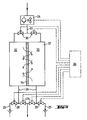
- a homogeneous symmetrical membrane 34 divides a pressure vessel 37 into a chamber 32 and a chamber 33.
- each of the two chambers in the pressure vessel 37 is used as the first or second chamber via a control and regulation arrangement 36, since the membrane 34, as said, in is permeable in both directions.
- a distributor line arrangement 31 with corresponding switching elements 30 is provided between a conveyor device 24 for supplying the solute-rich solution and the feed line to the respective chambers.
- switching devices 29 are provided in the drain lines 26 of the chambers 32 and 33, and a switching element 28 is provided in the concentrate drain 25. If the left chamber in FIG. 5 is operated as the first chamber, this can accumulate in the right chamber in FIG.
Landscapes
- Chemical & Material Sciences (AREA)
- Engineering & Computer Science (AREA)
- Water Supply & Treatment (AREA)
- Chemical Kinetics & Catalysis (AREA)
- Nanotechnology (AREA)
- Separation Using Semi-Permeable Membranes (AREA)
Applications Claiming Priority (2)
| Application Number | Priority Date | Filing Date | Title |
|---|---|---|---|
| CH2789/83 | 1983-05-20 | ||
| CH2789/83A CH673275A5 (fr) | 1983-05-20 | 1983-05-20 |
Publications (2)
| Publication Number | Publication Date |
|---|---|
| EP0126714A2 true EP0126714A2 (fr) | 1984-11-28 |
| EP0126714A3 EP0126714A3 (fr) | 1986-03-05 |
Family
ID=4241625
Family Applications (1)
| Application Number | Title | Priority Date | Filing Date |
|---|---|---|---|
| EP84810237A Withdrawn EP0126714A3 (fr) | 1983-05-20 | 1984-05-15 | Procédé et appareil pour le traitement de solutions par osmose inverse |
Country Status (3)
| Country | Link |
|---|---|
| EP (1) | EP0126714A3 (fr) |
| JP (1) | JPS60805A (fr) |
| CH (1) | CH673275A5 (fr) |
Cited By (32)
| Publication number | Priority date | Publication date | Assignee | Title |
|---|---|---|---|---|
| WO1995020038A1 (fr) * | 1994-01-19 | 1995-07-27 | Wissenschaftsförderung Der Deutschen Brauwirtschaft E.V. | Procede de clarification de biere par microfiltration tangentielle |
| US5484536A (en) * | 1991-09-17 | 1996-01-16 | Kabushiki Kaisha Toshiba | Filter backwash control method and apparatus |
| US5690829A (en) * | 1992-06-02 | 1997-11-25 | Lauer; Guenter | Conditioning process and device for producing pure water |
| EP0812805A3 (fr) * | 1996-06-15 | 1998-01-28 | Hans-Hermann Letzner | Procédé et dispositif de traitement d'eau froide |
| WO1997046305A3 (fr) * | 1996-05-31 | 1998-04-02 | Harold E Haney | Systeme de traitement de l'eau ameliore |
| WO1999026886A1 (fr) * | 1997-11-26 | 1999-06-03 | N.V. Waterleiding Friesland | Procede de purification d'eau, en particulier d'une eau souterraine, dans des conditions anaerobies, au moyen d'une cellule filtrante a membrane, dispositif de purification d'eau et eau potable obtenue par ce procede |
| US6099733A (en) * | 1996-12-09 | 2000-08-08 | Atp International Ltd. | Water treatment system |
| US6174437B1 (en) | 1996-05-31 | 2001-01-16 | Atp International Ltd. | Water treatment system |
| US6217770B1 (en) | 1998-08-14 | 2001-04-17 | Atp International | Apparatus and method for treatment of water |
| EP1312408A3 (fr) * | 2001-11-16 | 2003-08-06 | US Filter Wastewater Group, Inc. | Procédé de nettoyage de membranes |
| US7387723B2 (en) | 2004-04-22 | 2008-06-17 | Siemens Water Technologies Corp. | Filtration apparatus comprising a membrane bioreactor and a treatment vessel for digesting organic materials |
| US7455765B2 (en) | 2006-01-25 | 2008-11-25 | Siemens Water Technologies Corp. | Wastewater treatment system and method |
| US7563363B2 (en) | 2005-10-05 | 2009-07-21 | Siemens Water Technologies Corp. | System for treating wastewater |
| US7591950B2 (en) | 2004-11-02 | 2009-09-22 | Siemens Water Technologies Corp. | Submerged cross-flow filtration |
| US7632439B2 (en) | 2002-02-12 | 2009-12-15 | Siemens Water Technologies Corp. | Poly(ethylene chlorotrifluoroethylene) membranes |
| US8840783B2 (en) | 2007-05-29 | 2014-09-23 | Evoqua Water Technologies Llc | Water treatment membrane cleaning with pulsed airlift pump |
| US8858796B2 (en) | 2005-08-22 | 2014-10-14 | Evoqua Water Technologies Llc | Assembly for water filtration using a tube manifold to minimise backwash |
| US8956464B2 (en) | 2009-06-11 | 2015-02-17 | Evoqua Water Technologies Llc | Method of cleaning membranes |
| US9022224B2 (en) | 2010-09-24 | 2015-05-05 | Evoqua Water Technologies Llc | Fluid control manifold for membrane filtration system |
| US9023206B2 (en) | 2008-07-24 | 2015-05-05 | Evoqua Water Technologies Llc | Frame system for membrane filtration modules |
| US9533261B2 (en) | 2012-06-28 | 2017-01-03 | Evoqua Water Technologies Llc | Potting method |
| US9604166B2 (en) | 2011-09-30 | 2017-03-28 | Evoqua Water Technologies Llc | Manifold arrangement |
| US9675938B2 (en) | 2005-04-29 | 2017-06-13 | Evoqua Water Technologies Llc | Chemical clean for membrane filter |
| US9764289B2 (en) | 2012-09-26 | 2017-09-19 | Evoqua Water Technologies Llc | Membrane securement device |
| US9764288B2 (en) | 2007-04-04 | 2017-09-19 | Evoqua Water Technologies Llc | Membrane module protection |
| US9815027B2 (en) | 2012-09-27 | 2017-11-14 | Evoqua Water Technologies Llc | Gas scouring apparatus for immersed membranes |
| US9914097B2 (en) | 2010-04-30 | 2018-03-13 | Evoqua Water Technologies Llc | Fluid flow distribution device |
| US9925499B2 (en) | 2011-09-30 | 2018-03-27 | Evoqua Water Technologies Llc | Isolation valve with seal for end cap of a filtration system |
| US9962865B2 (en) | 2012-09-26 | 2018-05-08 | Evoqua Water Technologies Llc | Membrane potting methods |
| US10322375B2 (en) | 2015-07-14 | 2019-06-18 | Evoqua Water Technologies Llc | Aeration device for filtration system |
| US10427102B2 (en) | 2013-10-02 | 2019-10-01 | Evoqua Water Technologies Llc | Method and device for repairing a membrane filtration module |
| WO2023220738A1 (fr) * | 2022-05-13 | 2023-11-16 | The Regents Of The University Of Colorado, A Body Corporate | Procédés et systèmes à osmose inverse générant des cristaux de soluté |
Families Citing this family (4)
| Publication number | Priority date | Publication date | Assignee | Title |
|---|---|---|---|---|
| US4710710A (en) * | 1986-04-22 | 1987-12-01 | The Babcock & Wilcox Company | Scanning apparatus and method for inspection of header tube holes |
| US4806259A (en) * | 1987-06-15 | 1989-02-21 | The B. F. Goodrich Company | Membrane cleaning compositions containing phosphorous compounds |
| WO2007029291A1 (fr) * | 2005-09-01 | 2007-03-15 | Novel Technology Co., Ltd | Composition de nettoyage de membrane de séparation |
| JP2020104038A (ja) * | 2018-12-26 | 2020-07-09 | 三菱ケミカルアクア・ソリューションズ株式会社 | 水処理システム運転方法及び水処理システム |
Family Cites Families (8)
| Publication number | Priority date | Publication date | Assignee | Title |
|---|---|---|---|---|
| US3355382A (en) * | 1964-07-29 | 1967-11-28 | Waterdrink Inc | Centripetal acceleration method and apparatus |
| US3493495A (en) * | 1968-01-17 | 1970-02-03 | Morris Mendelson | Apparatus and process for the osmotic separation of water from a saline solution |
| US3846295A (en) * | 1972-04-06 | 1974-11-05 | Ultrascience Inc | Method and apparatus for use in water purification by reverse osmosis |
| FR2180436A1 (en) * | 1972-04-17 | 1973-11-30 | Degremont | Reverse osmosis - automatic membrane washing |
| US3992301A (en) * | 1973-11-19 | 1976-11-16 | Raypak, Inc. | Automatic flushing system for membrane separation machines such as reverse osmosis machines |
| US4341629A (en) * | 1978-08-28 | 1982-07-27 | Sand And Sea Industries, Inc. | Means for desalination of water through reverse osmosis |
| NL7905958A (nl) * | 1979-08-02 | 1980-09-30 | Wafilin Bv | Werkwijze en inrichting voor het spoelen van een membraanfiltratie-installatie. |
| JPS5626509A (en) * | 1979-08-13 | 1981-03-14 | Secr Defence Brit | Filtering apparatus |
-
1983
- 1983-05-20 CH CH2789/83A patent/CH673275A5/de not_active IP Right Cessation
-
1984
- 1984-05-15 EP EP84810237A patent/EP0126714A3/fr not_active Withdrawn
- 1984-05-21 JP JP59102450A patent/JPS60805A/ja active Pending
Cited By (44)
| Publication number | Priority date | Publication date | Assignee | Title |
|---|---|---|---|---|
| US5484536A (en) * | 1991-09-17 | 1996-01-16 | Kabushiki Kaisha Toshiba | Filter backwash control method and apparatus |
| US5690829A (en) * | 1992-06-02 | 1997-11-25 | Lauer; Guenter | Conditioning process and device for producing pure water |
| AU685905B2 (en) * | 1994-01-19 | 1998-01-29 | Wissenschaftsforderung Der Deutschen Brauwirtschaft E.V. | Beer clarification process by crossflow-microfiltration |
| WO1995020038A1 (fr) * | 1994-01-19 | 1995-07-27 | Wissenschaftsförderung Der Deutschen Brauwirtschaft E.V. | Procede de clarification de biere par microfiltration tangentielle |
| RU2176928C2 (ru) * | 1996-05-31 | 2001-12-20 | Харольд Е. ХЭНЭЙ | Улучшенная система для очистки воды |
| WO1997046305A3 (fr) * | 1996-05-31 | 1998-04-02 | Harold E Haney | Systeme de traitement de l'eau ameliore |
| US6174437B1 (en) | 1996-05-31 | 2001-01-16 | Atp International Ltd. | Water treatment system |
| EP0812805A3 (fr) * | 1996-06-15 | 1998-01-28 | Hans-Hermann Letzner | Procédé et dispositif de traitement d'eau froide |
| US6099733A (en) * | 1996-12-09 | 2000-08-08 | Atp International Ltd. | Water treatment system |
| WO1999026886A1 (fr) * | 1997-11-26 | 1999-06-03 | N.V. Waterleiding Friesland | Procede de purification d'eau, en particulier d'une eau souterraine, dans des conditions anaerobies, au moyen d'une cellule filtrante a membrane, dispositif de purification d'eau et eau potable obtenue par ce procede |
| US6217770B1 (en) | 1998-08-14 | 2001-04-17 | Atp International | Apparatus and method for treatment of water |
| EP1312408A3 (fr) * | 2001-11-16 | 2003-08-06 | US Filter Wastewater Group, Inc. | Procédé de nettoyage de membranes |
| US6955762B2 (en) | 2001-11-16 | 2005-10-18 | U. S. Filter Wastewater Group, Inc. | Method of cleaning membranes |
| US7632439B2 (en) | 2002-02-12 | 2009-12-15 | Siemens Water Technologies Corp. | Poly(ethylene chlorotrifluoroethylene) membranes |
| US7387723B2 (en) | 2004-04-22 | 2008-06-17 | Siemens Water Technologies Corp. | Filtration apparatus comprising a membrane bioreactor and a treatment vessel for digesting organic materials |
| US7591950B2 (en) | 2004-11-02 | 2009-09-22 | Siemens Water Technologies Corp. | Submerged cross-flow filtration |
| US9675938B2 (en) | 2005-04-29 | 2017-06-13 | Evoqua Water Technologies Llc | Chemical clean for membrane filter |
| US8894858B1 (en) | 2005-08-22 | 2014-11-25 | Evoqua Water Technologies Llc | Method and assembly for water filtration using a tube manifold to minimize backwash |
| US8858796B2 (en) | 2005-08-22 | 2014-10-14 | Evoqua Water Technologies Llc | Assembly for water filtration using a tube manifold to minimise backwash |
| US7563363B2 (en) | 2005-10-05 | 2009-07-21 | Siemens Water Technologies Corp. | System for treating wastewater |
| US7455765B2 (en) | 2006-01-25 | 2008-11-25 | Siemens Water Technologies Corp. | Wastewater treatment system and method |
| US9764288B2 (en) | 2007-04-04 | 2017-09-19 | Evoqua Water Technologies Llc | Membrane module protection |
| US10507431B2 (en) | 2007-05-29 | 2019-12-17 | Evoqua Water Technologies Llc | Membrane cleaning with pulsed airlift pump |
| US9206057B2 (en) | 2007-05-29 | 2015-12-08 | Evoqua Water Technologies Llc | Membrane cleaning with pulsed airlift pump |
| US8840783B2 (en) | 2007-05-29 | 2014-09-23 | Evoqua Water Technologies Llc | Water treatment membrane cleaning with pulsed airlift pump |
| US9573824B2 (en) | 2007-05-29 | 2017-02-21 | Evoqua Water Technologies Llc | Membrane cleaning with pulsed airlift pump |
| US9023206B2 (en) | 2008-07-24 | 2015-05-05 | Evoqua Water Technologies Llc | Frame system for membrane filtration modules |
| US8956464B2 (en) | 2009-06-11 | 2015-02-17 | Evoqua Water Technologies Llc | Method of cleaning membranes |
| US9914097B2 (en) | 2010-04-30 | 2018-03-13 | Evoqua Water Technologies Llc | Fluid flow distribution device |
| US10441920B2 (en) | 2010-04-30 | 2019-10-15 | Evoqua Water Technologies Llc | Fluid flow distribution device |
| US9630147B2 (en) | 2010-09-24 | 2017-04-25 | Evoqua Water Technologies Llc | Fluid control manifold for membrane filtration system |
| US9022224B2 (en) | 2010-09-24 | 2015-05-05 | Evoqua Water Technologies Llc | Fluid control manifold for membrane filtration system |
| US9604166B2 (en) | 2011-09-30 | 2017-03-28 | Evoqua Water Technologies Llc | Manifold arrangement |
| US9925499B2 (en) | 2011-09-30 | 2018-03-27 | Evoqua Water Technologies Llc | Isolation valve with seal for end cap of a filtration system |
| US11065569B2 (en) | 2011-09-30 | 2021-07-20 | Rohm And Haas Electronic Materials Singapore Pte. Ltd. | Manifold arrangement |
| US10391432B2 (en) | 2011-09-30 | 2019-08-27 | Evoqua Water Technologies Llc | Manifold arrangement |
| US9533261B2 (en) | 2012-06-28 | 2017-01-03 | Evoqua Water Technologies Llc | Potting method |
| US9764289B2 (en) | 2012-09-26 | 2017-09-19 | Evoqua Water Technologies Llc | Membrane securement device |
| US9962865B2 (en) | 2012-09-26 | 2018-05-08 | Evoqua Water Technologies Llc | Membrane potting methods |
| US9815027B2 (en) | 2012-09-27 | 2017-11-14 | Evoqua Water Technologies Llc | Gas scouring apparatus for immersed membranes |
| US10427102B2 (en) | 2013-10-02 | 2019-10-01 | Evoqua Water Technologies Llc | Method and device for repairing a membrane filtration module |
| US11173453B2 (en) | 2013-10-02 | 2021-11-16 | Rohm And Haas Electronic Materials Singapores | Method and device for repairing a membrane filtration module |
| US10322375B2 (en) | 2015-07-14 | 2019-06-18 | Evoqua Water Technologies Llc | Aeration device for filtration system |
| WO2023220738A1 (fr) * | 2022-05-13 | 2023-11-16 | The Regents Of The University Of Colorado, A Body Corporate | Procédés et systèmes à osmose inverse générant des cristaux de soluté |
Also Published As
| Publication number | Publication date |
|---|---|
| JPS60805A (ja) | 1985-01-05 |
| EP0126714A3 (fr) | 1986-03-05 |
| CH673275A5 (fr) | 1990-02-28 |
Similar Documents
| Publication | Publication Date | Title |
|---|---|---|
| EP0126714A2 (fr) | Procédé et appareil pour le traitement de solutions par osmose inverse | |
| EP0113387B1 (fr) | Procédé et appareil pour traiter des liquides, en particulier pour déminéraliser des solutions aqueuses | |
| DE69904945T2 (de) | Verfahren zur verminderung von ablagerungen in elektroentionisierungsanlagen | |
| DE2951703C1 (de) | Verfahren und Vorrichtung zur Verhinderung einer Verschmutzung von halbdurchlaessigen Trennmembranen | |
| DE69123644T2 (de) | Verfahren und Vorrichtung mit einer Umkehrosmose-Membran zum Konzentrieren einer Lösung | |
| DE102010043711B4 (de) | Wasseraufbereitungsverfahren | |
| DE102011012805B4 (de) | Aufbereitung von Rohsolen aus Meerwasserentsalzungsanlagen | |
| DE1792117A1 (de) | Verfahren und Vorrichtung zum Abtrennen von Ionen aus einer Loesung | |
| DE1150656B (de) | Kontinuierliche Vielkammerelektrodialyse waessriger Elektrolytloesungen unter Benutzung ionenselektiver Membranen | |
| DE69404734T2 (de) | Verfahren und Vorrichtung zur Dekontaminierung von Flüssigkeiten die ionische Metalle enthalten | |
| DE69612674T2 (de) | Verfahren zur entsalzung, und demineralisierung von säure und/oder metallsalzen enthaltenden lösungen | |
| DE102010043662B4 (de) | Brauereiabwasseraufbereitungsverfahren sowie Brauereiabwasseraufbereitungsvorrichtung | |
| EP0051104A1 (fr) | Procédé de traitement de l'eau contenant du nitrate | |
| DE60106498T2 (de) | Verfahren und Vorrichtung für die Reinigung und/oder Behandlung von edelmetallhaltigen Suspensionen mittels Membranfiltration | |
| DE2724724C3 (de) | Verfahren und Anlage zum Aufbereiten von schwermetallhaltigen Abwässern unter Rückgewinnung von Schwermetallen | |
| DE3338194C2 (de) | Verfahren zur Verhinderung der Niederschlagsbildung bei der Entionisierung von Rohwasser | |
| DE69727028T2 (de) | Verfahren zum Abtrennen und Rückgewinnen einer bestimmten Komponente | |
| DE60020077T2 (de) | Verfahren zur Weinsteinstabilisierung von Wein und Vorrichtung zu deren Implementierung | |
| EP0065489A1 (fr) | Procédé pour modifier la teneur en sels d'un liquide | |
| CH617099A5 (en) | Method for recovering materials by membrane separation | |
| EP3118163B1 (fr) | Dispositif de traitement de l'eau et procede de regeneration d'un dispositif de traitement de l'eau | |
| DE69311845T2 (de) | Apparat und Verfahren zur Wasserbehandlung | |
| EP0899238A1 (fr) | Procédé et appareil pour le traitement de l'eau par osmose inverse ou nanofiltration | |
| DE102010054477A1 (de) | Vorrichtung und Verfahren zur Aufbereitung von Wasser | |
| DE102016105080A1 (de) | Verfahren zur Reinigung von Elektrodialysemodulen |
Legal Events
| Date | Code | Title | Description |
|---|---|---|---|
| PUAI | Public reference made under article 153(3) epc to a published international application that has entered the european phase |
Free format text: ORIGINAL CODE: 0009012 |
|
| AK | Designated contracting states |
Designated state(s): AT BE CH DE FR GB IT LI LU NL SE |
|
| PUAL | Search report despatched |
Free format text: ORIGINAL CODE: 0009013 |
|
| AK | Designated contracting states |
Kind code of ref document: A3 Designated state(s): AT BE CH DE FR GB IT LI LU NL SE |
|
| 17P | Request for examination filed |
Effective date: 19860827 |
|
| 17Q | First examination report despatched |
Effective date: 19871012 |
|
| STAA | Information on the status of an ep patent application or granted ep patent |
Free format text: STATUS: THE APPLICATION IS DEEMED TO BE WITHDRAWN |
|
| 18D | Application deemed to be withdrawn |
Effective date: 19881005 |
|
| RIN1 | Information on inventor provided before grant (corrected) |
Inventor name: UEBERSAX, HEINZ |