EP0126801B1 - Chauffe-eau - Google Patents
Chauffe-eau Download PDFInfo
- Publication number
- EP0126801B1 EP0126801B1 EP83108783A EP83108783A EP0126801B1 EP 0126801 B1 EP0126801 B1 EP 0126801B1 EP 83108783 A EP83108783 A EP 83108783A EP 83108783 A EP83108783 A EP 83108783A EP 0126801 B1 EP0126801 B1 EP 0126801B1
- Authority
- EP
- European Patent Office
- Prior art keywords
- tubular member
- row
- orifice
- circular tubular
- water heater
- Prior art date
- Legal status (The legal status is an assumption and is not a legal conclusion. Google has not performed a legal analysis and makes no representation as to the accuracy of the status listed.)
- Expired
Links
- XLYOFNOQVPJJNP-UHFFFAOYSA-N water Substances O XLYOFNOQVPJJNP-UHFFFAOYSA-N 0.000 title claims description 57
- 230000000712 assembly Effects 0.000 claims description 21
- 238000000429 assembly Methods 0.000 claims description 21
- 229910010272 inorganic material Inorganic materials 0.000 claims description 2
- 239000011147 inorganic material Substances 0.000 claims description 2
- 238000009825 accumulation Methods 0.000 description 4
- 230000035508 accumulation Effects 0.000 description 4
- 230000002411 adverse Effects 0.000 description 4
- 238000010276 construction Methods 0.000 description 4
- 239000002245 particle Substances 0.000 description 4
- 230000000694 effects Effects 0.000 description 3
- 238000010438 heat treatment Methods 0.000 description 3
- 239000000463 material Substances 0.000 description 3
- 238000000034 method Methods 0.000 description 3
- 210000002445 nipple Anatomy 0.000 description 3
- 239000007787 solid Substances 0.000 description 3
- 230000002028 premature Effects 0.000 description 2
- 229910001220 stainless steel Inorganic materials 0.000 description 2
- 239000010935 stainless steel Substances 0.000 description 2
- 238000003466 welding Methods 0.000 description 2
- 229910000639 Spring steel Inorganic materials 0.000 description 1
- 239000000919 ceramic Substances 0.000 description 1
- 238000004140 cleaning Methods 0.000 description 1
- 238000002485 combustion reaction Methods 0.000 description 1
- 238000005260 corrosion Methods 0.000 description 1
- 230000007797 corrosion Effects 0.000 description 1
- 230000001419 dependent effect Effects 0.000 description 1
- 238000005485 electric heating Methods 0.000 description 1
- 239000007789 gas Substances 0.000 description 1
- 238000007373 indentation Methods 0.000 description 1
- 238000009434 installation Methods 0.000 description 1
- 239000007788 liquid Substances 0.000 description 1
- 239000012811 non-conductive material Substances 0.000 description 1
- 230000001376 precipitating effect Effects 0.000 description 1
- 239000011343 solid material Substances 0.000 description 1
- 238000003756 stirring Methods 0.000 description 1
- 239000000725 suspension Substances 0.000 description 1
- 238000010408 sweeping Methods 0.000 description 1
Images
Classifications
-
- F—MECHANICAL ENGINEERING; LIGHTING; HEATING; WEAPONS; BLASTING
- F24—HEATING; RANGES; VENTILATING
- F24H—FLUID HEATERS, e.g. WATER OR AIR HEATERS, HAVING HEAT-GENERATING MEANS, e.g. HEAT PUMPS, IN GENERAL
- F24H1/00—Water heaters, e.g. boilers, continuous-flow heaters or water-storage heaters
- F24H1/18—Water-storage heaters
- F24H1/20—Water-storage heaters with immersed heating elements, e.g. electric elements or furnace tubes
- F24H1/205—Water-storage heaters with immersed heating elements, e.g. electric elements or furnace tubes with furnace tubes
-
- F—MECHANICAL ENGINEERING; LIGHTING; HEATING; WEAPONS; BLASTING
- F24—HEATING; RANGES; VENTILATING
- F24H—FLUID HEATERS, e.g. WATER OR AIR HEATERS, HAVING HEAT-GENERATING MEANS, e.g. HEAT PUMPS, IN GENERAL
- F24H9/00—Details
- F24H9/12—Arrangements for connecting heaters to circulation pipes
- F24H9/13—Arrangements for connecting heaters to circulation pipes for water heaters
- F24H9/133—Storage heaters
Definitions
- the invention relates to a water heater according to the preamble part of claim 1.
- a longstanding problem in the water heater industry is the tendency of dissolved solid particles to precipitate out of the water being heated, which particles will accumulate on the bottom of the tank, causing adverse operation and tank failure.
- Prior constructions directed to this problem are disclosed in US-A-4,157,077, US-A-4,257,355 and US-A-4.,263,879, the last one disclosing a water heater according to the preamble part of claim 1.
- the latter water heater includes an agitator assembly having a circular tubular member which is positioned between the outer row of flue tubes and the tank wall with all orifices extending only in a horizontal plane, in other words, parallel to the bottom.
- venturi fitting being directed upwardly in the center of the tank, and being disposed on a straight portion which extends from a connection point to the inner side of the ring portion. Due this latter feature, the known water heater is relatively complicated structurally and, although a certain swirling and sweeping action is possible, the effect of this known arrangement is not satisfactory. Thus, the generic water heater also suffers from the before-mentioned drawback that there is a tendency for dissolved solid par- tides to precipitate out of the water being heated. If the scale accumulations are not periodically removed bysometypeoftankcieaning procedure, theywill gradually build up and harden, causing an adverse effect on the heating efficiency of the unit and, in many cases, will ultimately cause a premature failure of the heater tank.
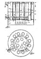
- the water heater of the present invention is comprised of a tank wall 10, a tank top member 12 and a tank bottom member 14.
- Top and bottom members 12 and 14 are provided with a plurality of aligned openings 16 and 18, respectively, in which flue tubes 20 are mounted (Fig. 1 does not show a complete set of flue tubes 20).
- Tank top and bottom members 12 and 14 are sealed to the tank wall 10 and to the flue tubes 20 by any suitable means such as welding to form a liquid tight tank having a water heating chamber 22 therein.
- a hot water outlet fitting 23 is provided in the top portion of the tank wall 10.
- the flue tube pattern shown in Fig. 2 is typical.
- the flue tubes 20 are positioned in an outer row designated by numeral 24 and an inner row designated by reference number 26.
- the water heater tank is mounted on a support base 28 which houses a burner 30 of conventional construction. Burner 30 is shown schematically in Fig. 1.
- Agitator assembly 32 is mounted in the lower portion of tank chamber 22 in the lower portion of tank chamber 22.
- Agitator assembly 32 is comprised of a circular tubular member 34 and a straight inlet tubular member 36 connected to the circular member 34 at point 38 by any suitable means such as welding.
- members 34 and 36 are made of heat and corrosion resistant material such as stainless steel.
- Inlet tube 36 extends through the tank wall 10 and fits inside a sleeve 40 which, in turn, is sealed inside a nipple 42.
- Sleeve 40 is made of an electrically nonconductive material such as plastic.
- Nipple 42 is threaded into a spud 44 which is welded to the tank wall 10.
- Nipple 42 is connected to a source of water under pressure by any suitable means (not shown).
- circular tubular member 34 of the agitator assembly 32 is located between the outer row 24 and the inner row 26 of flue tubes 20. More specifically, member 34 is located internally of and closely adjacent the outer row 24 of flue tubes 20. The significance of this location will be explained in detail hereinafter.
- Circular tubular member 34 is provided with three (3) rows of orifice assemblies 46; i.e., one row on the inner side of the member, a second row on the outer side of the member and a third row on the top of the member.
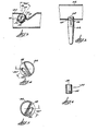
- Orifice assemblies 46 are of identical construction and are mounted on member 34 in an identical manner. In the preferred embodiment, orifice assemblies 46 are mounted on member 34 by the following procedure. Referring to Fig. 3, the first step is to form an indentation in the wall of member 34 to provide a substantially flat angled wall portion 48. This can be accomplished by any suitable means such as an hydraulic press. The next step is to punch or drill an opening 50 in wall 48.
- orifice assembly 46 is comprised of two parts, namely, a mounting clip 52 and an orifice member 54.
- Clips 52 preferably made of spring steel
- Orifice members 54 are of cylindrical shape and have a flow passageway 56 therethrough.
- orifice members 54 are made of an inorganic material such as ceramic and have an external groove 58 in one end thereof adapted for snap engagement with shoulders 60 formed in the end of mounting clips 52. It will be appreciated from the foregoing description that to install an orifice assembly 46 in tubular member 34, a mounting clip 52 is first snapped into opening 50 and then an orifice member 54 is snapped into clip 52 to complete the installation.
- the row of orifice assemblies 46 on the top of member 32 are positioned so that the axis of each assembly is directed upwardly and at an angle with respect to the verticle. As indicated in Fig. 3 in the preferred embodiment, such angle is approximately 35°.
- the orifice assemblies 46 on the inner and outer sides of tubular member 34 extend substantially tangential with respect to the circular axis of tube 34, i.e. at an angle with respect to a radius line extending through orifice openings 50.
- Orifice assemblies also extend downwardly with respect to a horizontal plane extending through the axis of member 34. As noted in Figs. 4 and 5 in the preferred embodiment, such downward angle from the horizontal is approximately 30°. In the preferred embodiment, such tangential angle is approximately 35° with respect to a radius line through each orifice opening 50.
- orifice assemblies 46 in the inner, outer and top rows all extend in the same direction with respect to the axis of tubular member 34, i.e., either in a clockwise or counterclockwise direction with respect to the axis of tubular member 32.
- agitator assembly 32 is mounted in the lower portion of the water heater chamber 22 in a spaced relationship with respect to the bottom 14 of the water heater tank. As shown in Fig. 7, the agitator assembly is supported in such spaced relationship with the tank bottom 14 by means of a plurality of leg members 62.
- leg members 62 are of plastic material and have a groove 64 and a slot 65 therein dimensioned for snap engagement with openings 66 in the bottom of tubular member 32.
- the inlet tube 36 and its mounting engagement in tank wall 10 also serves to provide support for the agitator assembly 32 in its desired position in the bottom of the water heater tank.
- the bottom of agitator assembly 32 is spaced as close to the tank bottom 14 as is practicable. In the embodiment shown and described herein, the distance is approximately 1-5/8 inches (41 mm).
- the water in chamber 22 will be heated by the hot gases and products of combustion passing through flue tubes 20 from burner 30 or in the case of an electric heater, the water will be heated by an electric heating element.
- the cold water drawn into the tank each time hot water is drawn off the top will be expelled into chamber 22 through orifice members 54 in the form of a plurality of jet-like streams.
- the streams emanating from the outer row of orifices in member 34 will be directed somewhat downwardly at a tangential angle with respect of the flue tubes 20 in the outer row.
- the streams emanating from the inner row of orifices on member 34 will be directed somewhat downwardly and at a tangential angle with respect to the flue tubes 20 in the inner row 26.
- the streams emanating from the upper row of orifices on member 34 will be directed upwardly at an angle with respect to the axis of tubular member 34.
- jet-like streams emanating from the outer row of orifices will effectively sweep the tank bottom around the base of flue tubes 20 in row 24.
- the jet-like streams emanating from the inner row of orifices will effectively sweep the tank bottom around the base of flue tubes 20 in inner row 26.
- the jet-like streams emanating from the top row of orifices will enhance the swirling action produced by the jet-like streams emanating from the inner and outer rows of orifices and will further provide an upwardly directed flow component to the overall swirling action.
- the agitator assembly means 32 is dimensioned so that the aggregate size of flow passageways 56 in orifice members 54 is less than the size of the flow passageway through inlet tube 36. With such relationship, the velocity of the water flowing through the orifices 56 will be greater than the velocity of water flowing through inlet tube 36 from the source of cold water under pressure.
- inlet tube 36 is made from 1-1/8 inch (28,6 mm) O.D. stainless steel tubing and passageways 56 in orifice members 54 have a diameter .2 inches (5,08 mm). With such dimensions, the ratio of the total area of the flow passageways 56 in the orifices 56 (total of 21 orifices) will be approximately 84% of the flow area through inlet tube 36.
Landscapes
- Engineering & Computer Science (AREA)
- Physics & Mathematics (AREA)
- Thermal Sciences (AREA)
- Chemical & Material Sciences (AREA)
- Combustion & Propulsion (AREA)
- Mechanical Engineering (AREA)
- General Engineering & Computer Science (AREA)
- Heat-Pump Type And Storage Water Heaters (AREA)
Claims (9)
étant caractérisé en ce que
Applications Claiming Priority (2)
| Application Number | Priority Date | Filing Date | Title |
|---|---|---|---|
| US49801983A | 1983-05-25 | 1983-05-25 | |
| US498019 | 1983-05-25 |
Publications (3)
| Publication Number | Publication Date |
|---|---|
| EP0126801A2 EP0126801A2 (fr) | 1984-12-05 |
| EP0126801A3 EP0126801A3 (en) | 1985-06-19 |
| EP0126801B1 true EP0126801B1 (fr) | 1989-01-11 |
Family
ID=23979291
Family Applications (1)
| Application Number | Title | Priority Date | Filing Date |
|---|---|---|---|
| EP83108783A Expired EP0126801B1 (fr) | 1983-05-25 | 1983-09-06 | Chauffe-eau |
Country Status (3)
| Country | Link |
|---|---|
| EP (1) | EP0126801B1 (fr) |
| CA (1) | CA1215276A (fr) |
| DE (1) | DE3378927D1 (fr) |
Families Citing this family (5)
| Publication number | Priority date | Publication date | Assignee | Title |
|---|---|---|---|---|
| US4791888A (en) * | 1987-09-11 | 1988-12-20 | State Industries, Inc. | Water heater tank construction |
| US4972804A (en) * | 1989-04-25 | 1990-11-27 | Alexander T. Kindling | Method and apparatus for organizing the flow of fluid in a vertical steam generator |
| US5165472A (en) * | 1991-03-18 | 1992-11-24 | Louis Cloutier | Heat exchanger with fluid injectors |
| DE19638851C1 (de) * | 1996-09-21 | 1998-02-26 | Oschatz Gmbh | Dampferzeuger |
| CA2239007C (fr) * | 1997-05-29 | 2008-01-22 | Eric M. Lannes | Raccord d'admission pour chauffe-eau |
Family Cites Families (3)
| Publication number | Priority date | Publication date | Assignee | Title |
|---|---|---|---|---|
| US4157077A (en) * | 1977-11-25 | 1979-06-05 | Lindahl John R | Water heater |
| US4263879A (en) * | 1977-11-25 | 1981-04-28 | State Industries, Inc. | Water heater |
| US4257355A (en) * | 1979-08-17 | 1981-03-24 | A. O. Smith Corporation | Cold water inlet tube |
-
1983
- 1983-08-04 CA CA000433924A patent/CA1215276A/fr not_active Expired
- 1983-09-06 EP EP83108783A patent/EP0126801B1/fr not_active Expired
- 1983-09-06 DE DE8383108783T patent/DE3378927D1/de not_active Expired
Also Published As
| Publication number | Publication date |
|---|---|
| EP0126801A2 (fr) | 1984-12-05 |
| EP0126801A3 (en) | 1985-06-19 |
| CA1215276A (fr) | 1986-12-16 |
| DE3378927D1 (en) | 1989-02-16 |
Similar Documents
| Publication | Publication Date | Title |
|---|---|---|
| US4838211A (en) | Water heater construction and method of heating water | |
| US4505231A (en) | Water heater construction with sediment removal means | |
| US5740315A (en) | Fluid heating apparatus | |
| US4263879A (en) | Water heater | |
| EP0239189B1 (fr) | Chauffe-eau/chaudière au gaz et leur brûleur | |
| US4157077A (en) | Water heater | |
| US4651714A (en) | High efficiency water heater | |
| EP0398454A2 (fr) | Construction d'un réchauffeur d'eau | |
| US4512289A (en) | Water heater with combination magnetic and agitator means | |
| US6508208B1 (en) | Water heater with arrangement for preventing substantial accumulation of sediment and method of operating same | |
| US4898124A (en) | Scale agitator | |
| CA1215276A (fr) | Chauffe-eau, et son fonctionnement | |
| ZA854222B (en) | A vertical tube heat exchanger panel for waste-recovery boilers such as black liquid boilers or household waste incincerator furnaces,and methods of manufacture | |
| CA2376579C (fr) | Appareil de chauffage domestique a combustible muni d'une chambre a combustion a ailettes a plaque pare-flamme | |
| US7500454B2 (en) | High efficiency water heater | |
| CN215026122U (zh) | 一种医药制备用节能型蒸馏塔 | |
| US5279261A (en) | Downfired boiler having vertical heat transfer tubes | |
| CA1053564A (fr) | Bruleur de chauffe-eau | |
| SU1318283A1 (ru) | Аппарат с многоступенчатым псевдоожиженным слоем | |
| RU2759582C1 (ru) | Двухконтурный газовый водонагреватель | |
| US4998007A (en) | Electrically heated reservoir having a preassembled plural tube continuous flow heating unit | |
| EP0306978B1 (fr) | Construction d'un réservoir d'eau pour un chauffe-eau | |
| SU1721424A1 (ru) | Вертикальный пленочный теплообменник | |
| SU1003866A1 (ru) | Контактное устройство дл тепломассообменных аппаратов | |
| EP0295967B1 (fr) | Dispositif pour chauffer indirectement un liquide |
Legal Events
| Date | Code | Title | Description |
|---|---|---|---|
| PUAI | Public reference made under article 153(3) epc to a published international application that has entered the european phase |
Free format text: ORIGINAL CODE: 0009012 |
|
| AK | Designated contracting states |
Designated state(s): DE FR GB |
|
| PUAL | Search report despatched |
Free format text: ORIGINAL CODE: 0009013 |
|
| AK | Designated contracting states |
Designated state(s): DE FR GB |
|
| 17P | Request for examination filed |
Effective date: 19851210 |
|
| 17Q | First examination report despatched |
Effective date: 19860326 |
|
| GRAA | (expected) grant |
Free format text: ORIGINAL CODE: 0009210 |
|
| AK | Designated contracting states |
Kind code of ref document: B1 Designated state(s): DE FR GB |
|
| REF | Corresponds to: |
Ref document number: 3378927 Country of ref document: DE Date of ref document: 19890216 |
|
| ET | Fr: translation filed | ||
| PLBE | No opposition filed within time limit |
Free format text: ORIGINAL CODE: 0009261 |
|
| STAA | Information on the status of an ep patent application or granted ep patent |
Free format text: STATUS: NO OPPOSITION FILED WITHIN TIME LIMIT |
|
| 26N | No opposition filed | ||
| REG | Reference to a national code |
Ref country code: GB Ref legal event code: IF02 |
|
| PGFP | Annual fee paid to national office [announced via postgrant information from national office to epo] |
Ref country code: GB Payment date: 20020823 Year of fee payment: 20 |
|
| PGFP | Annual fee paid to national office [announced via postgrant information from national office to epo] |
Ref country code: FR Payment date: 20020920 Year of fee payment: 20 |
|
| PGFP | Annual fee paid to national office [announced via postgrant information from national office to epo] |
Ref country code: DE Payment date: 20021030 Year of fee payment: 20 |
|
| PG25 | Lapsed in a contracting state [announced via postgrant information from national office to epo] |
Ref country code: GB Free format text: LAPSE BECAUSE OF EXPIRATION OF PROTECTION Effective date: 20030905 |
|
| REG | Reference to a national code |
Ref country code: GB Ref legal event code: PE20 |