EP0126912B1 - Bandsäge zum Teilen von Tierkörpern - Google Patents
Bandsäge zum Teilen von Tierkörpern Download PDFInfo
- Publication number
- EP0126912B1 EP0126912B1 EP84103858A EP84103858A EP0126912B1 EP 0126912 B1 EP0126912 B1 EP 0126912B1 EP 84103858 A EP84103858 A EP 84103858A EP 84103858 A EP84103858 A EP 84103858A EP 0126912 B1 EP0126912 B1 EP 0126912B1
- Authority
- EP
- European Patent Office
- Prior art keywords
- belt
- band saw
- saw
- band
- saw according
- Prior art date
- Legal status (The legal status is an assumption and is not a legal conclusion. Google has not performed a legal analysis and makes no representation as to the accuracy of the status listed.)
- Expired
Links
Images


Classifications
-
- B—PERFORMING OPERATIONS; TRANSPORTING
- B23—MACHINE TOOLS; METAL-WORKING NOT OTHERWISE PROVIDED FOR
- B23D—PLANING; SLOTTING; SHEARING; BROACHING; SAWING; FILING; SCRAPING; LIKE OPERATIONS FOR WORKING METAL BY REMOVING MATERIAL, NOT OTHERWISE PROVIDED FOR
- B23D55/00—Sawing machines or sawing devices working with strap saw blades, characterised only by constructional features of particular parts
- B23D55/08—Sawing machines or sawing devices working with strap saw blades, characterised only by constructional features of particular parts of devices for guiding or feeding strap saw blades
- B23D55/082—Devices for guiding strap saw blades
-
- Y—GENERAL TAGGING OF NEW TECHNOLOGICAL DEVELOPMENTS; GENERAL TAGGING OF CROSS-SECTIONAL TECHNOLOGIES SPANNING OVER SEVERAL SECTIONS OF THE IPC; TECHNICAL SUBJECTS COVERED BY FORMER USPC CROSS-REFERENCE ART COLLECTIONS [XRACs] AND DIGESTS
- Y10—TECHNICAL SUBJECTS COVERED BY FORMER USPC
- Y10T—TECHNICAL SUBJECTS COVERED BY FORMER US CLASSIFICATION
- Y10T83/00—Cutting
- Y10T83/707—By endless band or chain knife
- Y10T83/7226—With means to guard the tension
Definitions
- the invention relates to a band saw for dividing carcasses with a tensioning device for tensioning the saw band endlessly rotating around two rollers and two cabinet guides through which the cutting run of the saw band is guided so as to be approximately aligned in the plane of rotation of the two rollers.
- Such a band saw is known from DE-OS 31 23 439.
- the saw band used in such saws wears out relatively quickly and has to be replaced frequently. If the band saw is used in a slaughter street, such a band change requires an interruption in the cycle.
- the tape change must therefore be as simple and quick as possible.
- the object of the present invention is to improve the band saw described at the outset in such a way that the saw band can be replaced simply and quickly.
- the invention provides that the tensioning device has at least one first spring through which the saw band is pretensioned with a relatively low basic tension, that the tensioning device has at least one further spring through which the saw band receives its final tension and that a working member is provided, by means of which the tensioning force of the further spring or springs for changing the band can be canceled.
- the arrangement of the first spring means that the saw band can be quickly placed on the two rollers in a few simple steps. With the low pretension, it is then possible to insert the cutting strand of the saw band into the cabinet guides without any significant effort, and possibly to lock it into the working position. Only then is the full clamping force applied to the saw band. The band change can be carried out particularly quickly and safely while protecting the saw band.
- the working member can be acted upon with a pressure medium, the tensioning force of the further spring or springs being able to be canceled by the pressure of the pressure medium and the tensioning force of the further spring tensioning the saw band without pressure medium being applied to the working cylinder, the band sawing operation is safe, one permanent pressurization of the working member is not necessary.
- the further spring can be formed particularly advantageously by a plate spring assembly.
- the working member can be a one-sided working cylinder, in which case the additional spring on the piston side opposite the pressure chamber can be arranged in a manner that saves construction length and acts directly on the piston.
- the working member and the further spring can be designed to be particularly simple in terms of construction as an easily replaceable structural unit if the piston has a plunger protruding from the working cylinder housing, by means of which one of the rollers can be moved relative to the other roller.
- a reduction in the construction weight with a short overall length can be achieved in that the piston of the working cylinder is firmly connected to a guide rod guided by the further spring and in that the free end of this guide rod is guided in a preload adjusting screw.
- the plunger can be formed by the extended guide rod guided by the piston, so that the piston can be made as short as possible.
- the preload of the additional spring is increased via the working cylinder. The entire spring preload is absorbed by the working cylinder and is not transferred to the saw band.
- the cabinet guides are each slidable or pivotable relative to the cutting run of the saw band by means of a working member, preferably a working cylinder, the replacement of a saw band is made considerably easier in a time-saving manner.
- the actual setting process can then practically automatically be automatically connected to the tensioning of the saw band, the setting process being carried out briefly before the tensioning process in order to keep the saw band stress as low as possible.
- the band tension can first be released via the working cylinder acting on the further spring and only then the cabinet guides can be pushed back or swiveled to release the saw band, whereas then vice versa for tensioning the saw band
- Cabinet guides are returned from their band change position to their cabinet position and then shortly thereafter the further spring for achieving the final saw band tension is released again by the working member acting on them.
- the handling can be done manually with an appropriate switch lock mechanically or electrically by changeover switch only in the specified order, if necessary also limit, tension or relax, unblock via time delay switches.
- the cabinet guide can particularly advantageously be rotated coaxially to the cutting run of the saw band by approximately 90 °.
- the cabinet guide can be rotatably guided on a cylindrical, slotted guide tube, which runs coaxially with the saw band and surrounds the saw band. Part of the saw band is guided through the guide tube at the same time. If the saw band breaks, the saw band cannot be thrown off.
- the cabinet guide can be provided at the end of a pivoting lever that can be pivoted by the working cylinder, wherein the pivoting plane can lie in the cutting plane of the saw band or in a plane perpendicular to the cutting plane of the saw band.
- the cabinet guide can be formed by two jaws which can be moved relative to one another in a pair of pliers and through which the saw band is guided in an interlocked manner in the closed state.
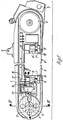
- the band saw has a support frame 1 which is provided with suspension eyes 2 for weight relief or connection to a handling device.
- a motor-driven roller 3 is provided in the carrier and a further roller 4 is provided at a distance therefrom in the same plane of rotation, around which a saw band 5 is guided.
- the cutting run 6 of the saw band 5 facing away from the carrier frame 1 is guided over 90 ° by means of two spaced-apart cabinet guides 7, 7 ', so that between these cabinet guides the cutting run 6 lies in the plane of the rotating rollers 3 and in this plane can cut.
- the guide jaws 10, 10 ' are made of hard metal.
- guide rollers can also be arranged in a known manner.
- the cutting run 6 of the saw band is guided through these cabinet guides 7, 7'.
- the cabinet guides 7, 7 ' can be retracted by the working cylinders 8, 8'.
- the saw blade 5 can then be placed freely on the rollers 3, 4, as will be described in more detail later.
- the roller 4 is rotatably mounted on a bearing pin 11, the bearing pin 11 itself being fastened in a slide 12 which is displaceably guided in the carrier frame 1.
- the displaceable carriage 12 serves to tension the saw blade 5.
- a first spring 13 is arranged, which is supported with one end on the carriage 12 and via a plunger 14 on the support frame 1, as shown in FIG Fig. 3 can be seen.
- the pretension of the first spring 13 is approximately 5 kp (50 N), so that the pretensioning force can easily be overcome by hand for mounting and removing a saw blade 5.
- a tensioning device 15 is also arranged on the support frame 1, approximately in the plane of rotation of the saw blade 5.
- This tensioning device 15 has a further spring 16, which is accommodated as a plate spring assembly in a multi-part housing 17.
- the spring 16 is supported on the one hand on a preload adjusting screw 18 for setting the spring preload. Its other end lies against the piston 19 of a working member in the form of a working cylinder.
- a guide rod 21 which is guided through the spring 16 and which is displaceably guided in the preload adjusting screw 18 (FIG. 2).
- the side of the piston 19 opposite the spring 16 can be supplied with compressed air, for example, via a line 22, as a result of which the biasing force of the spring 16 is overcome and the piston is displaced towards this spring 16.
- a plunger 23 which protrudes from the housing 17 and which is supported on the slide 12 is withdrawn. This eliminates the clamping force that usually acts on the slide 12 via the tappet 23 and is approximately 500 to 600 kp (5 to 6 kN).
- the spring 16 and the plunger 23 are located centrally with respect to the rotating saw band 5.
- the working member 20 When assembling a saw band 5, the working member 20 is pressurized, so that the carriage 12 is easily displaceable against the tension spring 13 and thus the distance between the two rollers 3, 4 is reduced.
- the saw band 5 can then be placed on the two rollers 3, 4.
- the carriage 12 is released again and the first spring 13 braces the saw band with a tensioning force of approx. 5 kp (50 N).
- the two cabinet guides 7, 7 ' are extended, for example, by a pneumatic control, and the cutting strand between the guides 10, 10' of the cabinet guides 7, 7 'is threaded and folded into the position shown in FIG. 1.
- the working member 20 is relieved of pressure again, so that the final tension of the saw blade is reached with a tensioning force of about 500 to 600 kp (5 to 6 kN).
- the switching of the working elements 8 and 20 can be briefly delayed via a delay circuit take place so that a quick change of saw blade is made possible.
- the working member 20 is first pressurized in reverse and only then is the working member 8 reversed by reversing the pressurizing, so that the piston rod 9 or 9 'is drawn in and the saw blade is released from the cabinet guides 7, 7' becomes.
- FIGS. 5 to 10 show three further embodiments of the cabinet guides 7.
- a guide tube 24 is fastened to the carrier frame 1, on which the guide jaws 10 are held so as to be pivotable through 90 ° via a tubular holder 25.
- the bracket 25 can be pivoted through a pivot lever 26 and an intermediate member 27 by the working member 8 in the direction of arrow 28 about 90 °.
- the guide tube 24 and holder 25 are slotted so as to enable easy and quick replacement. In the operating position, the slots are covered, so that it is difficult to shear off in the event of a saw blade break.
- the pivot lever 26 can be pivoted in the direction of arrow 28 by the working member 8 via the intermediate member 27, namely out of the circumferential plane of the saw blade 5, while in the embodiment of Figure 9 the pivot lever 26 can be pivoted in the circumferential plane of the saw band 5 .
- the cabinet guide 7 is shown in its working position with the cutting blade 6 of the saw blade 5 being set.
Landscapes
- Engineering & Computer Science (AREA)
- Mechanical Engineering (AREA)
- Sawing (AREA)
- Knives (AREA)
- Medicines Containing Plant Substances (AREA)
- Toys (AREA)
Description
- Die Erfindung betrifft eine Bandsäge zum Teilen von Tierkörpem mit einer Spannvorrichtung zum Spannen des endlos um zwei Rollen umlaufenden Sägebands und zwei Schränkführungen, durch die das schneidende Trumm des Sägebands etwa fluchtend in der Umlaufebene der beiden Rollen verschränkt geführt ist.
- Eine solche Bandsäge ist aus der DE-OS 31 23 439 bekannt. Das bei solchen Sägen verwendete Sägeband verschleißt relativ schnell und muß häufig ausgewechselt werden. Beim Einsatz der Bandsäge in einer Schlachtstraße bedingt ein solcher Bandwechsel eine Taktunterbrechung. Der Bandwechsel muß daher möglichst einfach und rasch erfolgen können.
- Aufgabe der vorliegenden Erfindung ist es, die eingangs beschriebene Bandsäge so zu verbessern, daß das Sägeband einfach und rasch ausgetauscht werden kann.
- Zur Lösung dieser Aufgabe sieht die Erfindung vor, daß die Spannvorrichtung mindestens eine erste Feder aufweist, durch die mit einer relativ niedrigen Grundspannung das Sägeband vorgespannt wird, daß die Spannvorrichtung mindestens eine weitere Feder aufweist, durch die das Sägeband seine Endspannung erhält und daß ein Arbeitsglied vorgesehen ist, durch das die Spannkraft der weiteren Feder bzw. Federn zum Bandwechsel aufhebbar ist.
- Durch die Anordnung der ersten Feder kann das Sägeband mit wenigen Handgriffen rasch auf die beiden Rollen aufgelegt werden. Mit der geringen Vorspannung ist es dann möglich, das schneidende Trumm des Sägebands ohne wesentlichen Kraftaufwand in die Schränkführungen einzuführen, und dabei gegebenenfalls in die Arbeitslage zu verschränken. Erst danach wird die volle Spannkraft auf das Sägeband aufgebracht. Der Bandwechsel kann so besonders rasch und sicher sägebandschonend erfolgen.
- Dadurch, daß als Arbeitsglied ein mit einem Druckmedium beaufschlagbarer Arbeitszylinder gewählt wird, wobei durch den Druck des Druckmediums die Spannkraft der weiteren Feder bzw. Federn aufhebbar ist und ohne Druckmediumbeaufschlagung des Arbeitszylinders die Spannkraft der weiteren Feder das Sägeband spannt, ist der Bandsägebetrieb sicher, eine dauernde Druckbeaufschlagung des Arbeitsglieds ist nicht erforderlich. Um große Spannkräfte bei möglichst geringen Federabmessungen raumsparend unterbringen zu können, kann besonders vorteilhaft die weitere Feder durch ein Tellerfederpaket gebildet sein. Zur weiteren Platzeinsparung kann das Arbeitsglied ein einseitig wirkender Arbeitszylinder sein, wobei dann die weitere Feder auf der dem Druckraum gegenüberliegenden Kolbenseite direkt auf den Kolben wirkend Baulänge einsparend angeordnet sein kann.
- Das Arbeitsglied und die weitere Feder können konstruktiv besonders einfach als leicht austauschbare für sich montierbare Baueinheit ausgebildet werden, wenn der Kolben einen aus dem Arbeitszylindergehäuse ragenden Stößel aufweist, über den eine der Rollen gegenüber der anderen Rolle verschiebbar ist.
- Eine Verringerung des Konstruktionsgewichts bei kurzer Baulänge kann dadurch erreicht werden, daß der Kolben des Arbeitszylinders fest mit einer durch die weitere Feder geführten Führungsstange verbunden ist und daß das freie Ende dieser Führungsstange in einer Vorspannungseinstellschraube geführt ist. Dabei kann der Stößel durch die durch den Kolben geführte verlängerte Führungsstange gebildet sein, um so den Kolben möglichst kurz ausbilden zu können. Zur Aufhebung der Endspannkraft des Sägebands wird über den Arbeitszylinder die Vorspannung der weiteren Feder erhöht. Die gesamte Federvorspannkraft wird vom Arbeitszylinder aufgenommen und nicht auf das Sägeband übertragen.
- Dadurch, daß die Schränkführungen jeweils mittels eines Arbeitsglieds, vorzugsweise eines Arbeitszylinders verschiebbar oder schwenkbar gegenüber dem schneidenden Trumm des Sägebands angeordnet sind, wird das Auswechseln eines Sägebands zeitsparend wesentlich erleichtert. Der eigentliche Schränkvorgang kann dann praktisch selbsttätig automatisch mit dem Spannen des Sägebands verbunden werden, wobei der Schränkvorgang kurzzeitig vor dem Spannvorgang ausgeführt wird, um die Sägebandbeanspruchung möglichst gering zu halten. Besonders vorteilhaft kann durch eine mechanische oder elektrische Steuerung bei einem Bandwechsel beim Entspannen zuerst über den auf die weitere Feder wirkenden Arbeitszylinder die Bandspannung aufgehoben werden und dann erst die Schränkführungen zur Freigabe des Sägebands zurückgeschoben oder geschwenkt werden, wogegen dann zum Spannen des Sägebands umgekehrt zuerst die Schränkführungen von ihrer Bandwechselstellung in ihre Schränkstellung zurückgeführt werden und dann kurzzeitig danach die weitere Feder zur Erzielung der Sägebandendspannung von dem auf sie wirkenden Arbeitsglied wieder freigegeben wird. Die Handhabung kann von Hand mit einer entsprechenden Schaltsperre mechanisch oder elektrisch durch Umschalter nur in der vorgegebenen Reihenfolge erfolgen, gegebenenfalls auch über Zeitverzögerungsschalter schränken, spannen bzw. entspannen, entschränken.
- Besonders vorteilhaft kann die Schränkführung koaxial zum schneidenden Trumm des Sägebands um etwa 90° drehbar geführt sein. Dazu kann die Schränkführung an einem zylindrischen zum Sägeband koaxial verlaufenden, das Sägeband umschließenden geschlitzten Führungsrohr drehbar geführt sein. So wird durch das Führungsrohr gleichzeitig ein Teil des Sägebands abgedeckt geführt. Bei einem Sägebandbruch kann dann das Sägeband nicht abgeschleudert werden.
- Bei einer anderen Ausführungsform kann die Schränkführung am Ende eines vom Arbeitszylinder schwenkbaren Schwenkhebel vorgesehen sein, wobei die Schwenkebene in der Schnittebene des Sägebands oder in einer zur Schnittebene des Sägebands senkrechten Ebene liegen kann.
- Bei einer weiteren Ausführungsform kann die Schränkführung durch zwei zangenartig gegeneinander bewegbare Backen gebildet werden, durch die in geschlossenem Zustand das Sägeband verschränkt geführt wird.
- Weitere erfindungsgemäße Ausbildungen sind den Unteransprüchen zu entnehmen und werden mit ihren Vorteilen in der nachstehenden Beschreibung näher erläutert. In den beigefügten Zeichnungen zeigt:
- Figur 1 eine Seitenansicht einer Bandsäge,
- Figur 2 einen Teilschnitt entlang der Linie 11-11 in Fig. 1 durch die Spannvorrichtung für das Sägeblatt, in größerem Maßstab,
- Figur 3 einen Teilschnitt entlang der Linie 111-111 in Fig. 1, die Lagerung der verstellbaren Rolle für das Sägeband mit einer Seitenansicht der Spannvorrichtung, in größerem Maßstab,
- Figur 4 einen Schnitt durch die Rollenlagerung entlang der Linie IV-IV in Fig. 3, senkrecht zum Schnitt 3 verlaufend,
- Figuren 5 und 6 zwei Ansichten, teilweise im Schnitt durch eine Schränkvorrichtung,
- Figuren 7 bis 10 den Figuren 5 und 6 entsprechende Ansichten zweier weiterer Ausführungsformen von Schränkführungen.
- Für alle entsprechenden Teile werden bei der Beschreibung der verschiedenen Ausführungsbeispiele die gleichen Bezugszeichen verwendet.
- Die Bandsäge weist ein Trägergestell 1 auf, das zur Gewichtsentlastung oder Verbindung mit einem Handhabungsgerät mit Aufhängeösen 2 versehen ist. Im Trägergestellt ist eine motorisch antreibbare Rolle 3 und im Abstand davon in der gleichen Umlaufebene eine weitere Rolle 4 vorgesehen, um die herum ein Sägeband 5 geführt ist. Das vom Trägergestell 1 abgewandte schneidende Trumm 6 des Sägebands 5 ist über zwei im Abstand voneinander angeordnete Schränkführungen 7, 7' um 90° verschränkt geführt, so daß zwischen diesen Schränkführungen das schneidende Trumm 6 in der Ebene der umlaufenden Rollen 3 liegt und in dieser Ebene schneiden kann. Die Schränkführungen 7, 7' bestehen jeweils aus einem Arbeitszylinder 8, 8', auf dessen freiem Ende einer Kolbenstange 9 bzw. 9' Führungsbacken 10, 10' parallel zueinander verlaufend angeordnet sind zwischen den gehärteten Führungsleisten. Zur Verschleißminderung bestehen die Führungsbacken 10, 10' aus Hartmetall. Anstelle der Fühfungsbacken 10, 10' können auch in bekannter Weise Führungsrollen angeordnet sein. Im ausgefahrenen Zustand der Kolbenstangen 9, 9' ist das schneidende Trumm 6 des Sägebands durch diese Schränkführungen 7, 7' geführt. Zum Auswechseln des Sägebands 5 können die Schränkführungen 7, 7' durch die Arbeitszylinder 8, 8' zurückgezogen werden. Das Sägeblatt 5 kann dann ungehindert auf die Rollen 3, 4 aufgelegt werden, wie dies später noch näher beschrieben wird.
- Die Rolle 4 ist auf einem Lagerbolzen 11 drehbar gelagert, wobei der Lagerbolzen 11 selber in einem im Trägergestell 1 verschiebbar geführten Schlitten 12 befestigt ist. Der verschiebbare Schlitten 12 dient zum Spannen des Sägblatts 5. Hierzu ist zur Erzielung einer relativ niedrigen Grundspannung im Schlitten 12 eine erste Feder 13 angeordnet, die sich mit ihrem einen Ende am Schlitten 12 und über einen Stößel 14 am Trägergestell 1 abstützt, wie dies in Fig. 3 erkennbar ist. Die Vorspannung der ersten Feder 13 beträgt ca. 5 kp (50 N), so daß die Vorspannkraft von Hand leicht zum Auf- und Abnehmen eines Sägeblatts 5 überwindbar ist.
- Als Baueinheit ist am Trägergestell 1 weiter eine Spannvorrichtung 15 etwa in der Umlaufebene des Sägeblatts 5 angeordnet. Diese Spannvorrichtung 15 weist eine weitere Feder 16 auf, die als Tellerfederpaket in einem mehrteiligen Gehäuse 17 untergebracht ist. Die Feder 16 stützt sich zur Einstellung der Federvorspannung einerseits auf einer Vorspannungseinstellschraube 18 ab. Ihr anderes Ende liegt am Kolben 19 eines Arbeitsglieds in Form eines Arbeitszylinders an. Um den Kolben 19 möglichst kurz zu halten, ist er mit einer durch die Feder 16 hindurchgeführten Führungsstange 21 befestigt, die verschiebbar in der Vorspannungseinstellschraube 18 geführt ist (Fig. 2). Die der Feder 16 gegenüberliegende Seite des Kolbens 19 ist über eine Leitung 22 bspw. mit Druckluft beaufschlagbar, wodurch die Vorspannkraft der Feder 16 überwunden und der Kolben gegen diese Feder 16 hin verschoben wird. Hierdurch wird ein Stößel 23, der aus dem Gehäuse 17 hervorsteht und der sich am Schlitten 12 abstützt, zurückgezogen. Damit entfällt die üblicherweise über den Stößel 23 auf den Schlitten 12 wirkende Spannkraft, die etwa 500 bis 600 kp (5 bis 6 kN) beträgt. Um ein Verkippen möglichst zu vermeiden, liegt die Feder 16 und der Stößel 23 mittig bezüglich des umlaufenden Sägebands 5.
- Bei der Montage eines Sägebands 5 wird das Arbeitsglied 20 druckbeaufschlagt, so daß der Schlitten 12 leicht gegen die Spannfeder 13 verschiebbar und somit der Abstand zwischen den beiden Rollen 3, 4 verkleinert wird. Es kann dann auf die beiden Rollen 3, 4 das Sägeband 5 aufgelegt werden. Danach wird der Schlitten 12 wieder freigegeben und durch die erste Feder 13 erfolgt eine Verspannung des Sägebands mit einer Spannkraft von ca. 5 kp (50 N). Danach werden die beiden Schränkführungen 7, 7' bspw. über eine pneumatische Steuerung ausgefahren und das schneidende Trumm zwischen die Führungen 10, 10' der Schränkführungen 7, 7' eingefädelt und in die in Fig. 1 dargestellte Lage verschränkt. Erst danach wird das Arbeitsglied 20 wieder druckentlastet, so daß die Endspannung des Sägeblatts mit einer Spannkraft von etwa 500 bis 600 kp (5 bis 6 kN) erreicht wird. Die Umschaltung der Arbeitsglieder 8 und 20 kann über eine Verzögerungsschaltung kurz verzögert erfolgen, so daß ein rascher Sägeblattwechsel ermöglicht wird. Zur Demontage des Sägeblatts 5 erfolgt in umgekehrter Weise zuerst eine Druckbeaufschlagung des Arbeitsglieds 20 und erst danach wird das Arbeitsglied 8 durch eine Umkehrung der Druckbeaufschlagung umgesteuert, so daß die Kolbenstange 9 bzw. 9' eingezogen und das Sägeblatt von den Schränkführungen 7, 7' freigegeben wird.
- In den Figuren 5 bis 10 sind drei weitere Ausführungsformen der Schränkführungen 7 dargestellt. Beim Ausführungsbeispiel der Figuren 5 und 6 ist am Trägergestell 1 ein Führungsrohr 24 befestigt, auf dem über eine rohrförmige Halterung 25 die Führungsbacken 10 um 90° schwenkbar gehalten sind. Die Halterung 25 ist über einen Schwenkhebel 26 und ein Zwischenglied 27 durch das Arbeitsglied 8 in Richtung des Pfeils 28 etwa um 90° verschwenkbar. Zur Aufnahme des Sägeblatts 5 sind Führungsrohr 24 und Halterung 25 geschlitzt, um so ein leichtes und rasches Auswechseln zu ermöglichen. In der Betriebsstellung sind die Schlitze überdeckt, so daß bei einem Sägebandbruch ein Abschleudem erschwert wird.
- Beim Ausführungsbeispiel der Figur 7 ist der Schwenkhebel 26 in Richtung des Pfeils 28 durch das Arbeitsglied 8 über das Zwischenglied 27 ausschwenkbar und zwar aus der Umlaufebene des Sägeblatts 5 heraus, während beim Ausführungsbeispiel der Figur 9 der Schwenkhebel 26 in der Umlaufebene des Sägebands 5 schwenkbar ist. In Figuren 5 bis 10 ist die Schränkführung 7 in ihrer Arbeitsstellung mit geschränkten schneidenden Trumm 6 des Sägebands 5 dargestellt.
Claims (18)
Priority Applications (1)
| Application Number | Priority Date | Filing Date | Title |
|---|---|---|---|
| AT84103858T ATE44669T1 (de) | 1983-05-30 | 1984-04-06 | Bandsaege zum teilen von tierkoerpern. |
Applications Claiming Priority (2)
| Application Number | Priority Date | Filing Date | Title |
|---|---|---|---|
| DE3319623A DE3319623C2 (de) | 1983-05-30 | 1983-05-30 | Bandsäge zum Teilen von Tierkörpern |
| DE3319623 | 1983-05-30 |
Publications (3)
| Publication Number | Publication Date |
|---|---|
| EP0126912A2 EP0126912A2 (de) | 1984-12-05 |
| EP0126912A3 EP0126912A3 (en) | 1987-02-04 |
| EP0126912B1 true EP0126912B1 (de) | 1989-07-19 |
Family
ID=6200268
Family Applications (1)
| Application Number | Title | Priority Date | Filing Date |
|---|---|---|---|
| EP84103858A Expired EP0126912B1 (de) | 1983-05-30 | 1984-04-06 | Bandsäge zum Teilen von Tierkörpern |
Country Status (4)
| Country | Link |
|---|---|
| US (1) | US4597132A (de) |
| EP (1) | EP0126912B1 (de) |
| AT (1) | ATE44669T1 (de) |
| DE (2) | DE3319623C2 (de) |
Families Citing this family (9)
| Publication number | Priority date | Publication date | Assignee | Title |
|---|---|---|---|---|
| FR2583673B1 (fr) * | 1985-06-25 | 1989-03-10 | Saint Gobain Vitrage | Dispositif de decoupe de feuilles de matiere plastique |
| DE3700253A1 (de) * | 1987-01-07 | 1988-07-21 | Freund Reinhard Maschbau | Bandsaege zum zerteilen von tierkoerpern |
| US5237897A (en) * | 1987-03-02 | 1993-08-24 | Seneca Sawmill Company | Automatic bandmill strain and saw tracking method and apparatus |
| US5364301A (en) * | 1993-11-22 | 1994-11-15 | Marine Machines, Inc. | Processing sea urchins for extracting gonads |
| NL1000260C2 (nl) * | 1995-04-28 | 1996-10-29 | Stork Rms Bv | Inrichting voor het delen van een botdeel bevattend stuk vlees. |
| US5819630A (en) * | 1996-05-09 | 1998-10-13 | T.S. Manufacturing Company | Bandsaw |
| WO2010014865A1 (en) * | 2008-07-31 | 2010-02-04 | Milwaukee Electric Tool Corporation | Band saw blade removal mechanism |
| US11407046B2 (en) * | 2018-11-27 | 2022-08-09 | Strategic Design LLC | Band saw with expanded cutting section |
| NZ788748A (en) | 2019-12-20 | 2023-06-30 | Scott Automation & Robotics Pty Ltd | A meat processing system |
Family Cites Families (5)
| Publication number | Priority date | Publication date | Assignee | Title |
|---|---|---|---|---|
| FR751826A (fr) * | 1932-05-26 | 1933-09-11 | Scies à ruban perfectionnées, permettant des grandes vitesses et grands rendements, par l'application de volants à bandages pneumatiques, pleins, creux, ou alvéolés | |
| DE724275C (de) * | 1939-08-06 | 1942-08-21 | Reich Maschf Gmbh Karl | Handbandsaege |
| DE827410C (de) * | 1949-12-23 | 1952-01-10 | Karl M Reich Fa | Handbandsaege mit ueber Leitscheiben und zwischen Fuehrungen hindurchlaufendem endlosem Saegeband |
| US2644492A (en) * | 1950-06-21 | 1953-07-07 | Continental Machines | Safety lock for band saw tensioning mechanism |
| US4327621A (en) * | 1979-10-26 | 1982-05-04 | Hobart Corporation | Self steering blade guide for a band saw |
-
1983
- 1983-05-30 DE DE3319623A patent/DE3319623C2/de not_active Expired
-
1984
- 1984-04-06 AT AT84103858T patent/ATE44669T1/de not_active IP Right Cessation
- 1984-04-06 EP EP84103858A patent/EP0126912B1/de not_active Expired
- 1984-04-06 DE DE8484103858T patent/DE3478998D1/de not_active Expired
- 1984-05-24 US US06/613,960 patent/US4597132A/en not_active Expired - Fee Related
Also Published As
| Publication number | Publication date |
|---|---|
| ATE44669T1 (de) | 1989-08-15 |
| EP0126912A2 (de) | 1984-12-05 |
| DE3478998D1 (en) | 1989-08-24 |
| EP0126912A3 (en) | 1987-02-04 |
| DE3319623A1 (de) | 1984-12-06 |
| DE3319623C2 (de) | 1985-09-05 |
| US4597132A (en) | 1986-07-01 |
Similar Documents
| Publication | Publication Date | Title |
|---|---|---|
| DE2412362C3 (de) | Federspannvorrichtung für das Sägeblatt einer Bandsäge | |
| DE60103472T2 (de) | Rohrabschneider | |
| DE69109338T2 (de) | Schneidscheibespindel, insbesondere für Teilmaschinen. | |
| DE2514836C2 (de) | Vorrichtung zum Durchschneiden eines Bogenstapels mit einem Rundmesser | |
| DE2434050C3 (de) | Zweiseitig schneidende Schaumstoffspaltmaschine | |
| CH654779A5 (de) | Pneumatisch angetriebene spannvorrichtung. | |
| EP0126912B1 (de) | Bandsäge zum Teilen von Tierkörpern | |
| DE4007449C1 (de) | ||
| DE69109693T2 (de) | Montage-grundkörper für führungsschienen. | |
| DE8713698U1 (de) | Vorrichtung zum Ausbreiten und Führen einer Warenbahn | |
| EP1814685B1 (de) | Hubsägemaschine | |
| EP1052046A2 (de) | Spanneinrichtung für Gegenstände, z.B. für zu bearbeitende Werkstücke | |
| DE3341424C2 (de) | Antriebsvorrichtung | |
| EP0249059B1 (de) | Druckluftantrieb für Stanz-, Schneid- und Prägeeinrichtungen | |
| DE2702993A1 (de) | Vorrichtung zum trennen von rollenmaterial | |
| DE4324627C1 (de) | Trennvorrichtung | |
| CH659965A5 (de) | Klemmvorrichtung fuer ein saegeblatt an einer saegenbearbeitungsmaschine. | |
| DE7918654U1 (de) | Spannvorrichtung fuer das saegeband einer bandsaegemaschine | |
| DE2618594C3 (de) | Vorrichtung zum Abtrennen aufeinanderfolgender Abschnitte von kontinuierlich vorlaufendem strangförmigen Gut | |
| DE4223230C1 (de) | Klemmeinrichtung für eine Druckplatte | |
| EP3061553A1 (de) | Vorrichtung zum bearbeiten von mit schneiden besetzten werkstücken umfassend eine klemmvorrichtung | |
| DE1602423C3 (de) | Biege- und Stanzautomat zum Herstellen von Formteilen aus Draht oder Band | |
| DE3700253A1 (de) | Bandsaege zum zerteilen von tierkoerpern | |
| DE2462533C2 (de) | Zweiseitig schneidende Schaumstoffspaltmaschine | |
| EP0023996B1 (de) | Plattensäge mit aufrechtem Gestell |
Legal Events
| Date | Code | Title | Description |
|---|---|---|---|
| PUAI | Public reference made under article 153(3) epc to a published international application that has entered the european phase |
Free format text: ORIGINAL CODE: 0009012 |
|
| AK | Designated contracting states |
Designated state(s): AT BE CH DE FR GB IT LI LU NL SE |
|
| PUAL | Search report despatched |
Free format text: ORIGINAL CODE: 0009013 |
|
| AK | Designated contracting states |
Kind code of ref document: A3 Designated state(s): AT BE CH DE FR GB IT LI LU NL SE |
|
| 17P | Request for examination filed |
Effective date: 19870320 |
|
| 17Q | First examination report despatched |
Effective date: 19880902 |
|
| GRAA | (expected) grant |
Free format text: ORIGINAL CODE: 0009210 |
|
| AK | Designated contracting states |
Kind code of ref document: B1 Designated state(s): AT BE CH DE FR GB IT LI LU NL SE |
|
| PG25 | Lapsed in a contracting state [announced via postgrant information from national office to epo] |
Ref country code: SE Effective date: 19890719 Ref country code: NL Effective date: 19890719 Ref country code: IT Free format text: LAPSE BECAUSE OF FAILURE TO SUBMIT A TRANSLATION OF THE DESCRIPTION OR TO PAY THE FEE WITHIN THE PRESCRIBED TIME-LIMIT;WARNING: LAPSES OF ITALIAN PATENTS WITH EFFECTIVE DATE BEFORE 2007 MAY HAVE OCCURRED AT ANY TIME BEFORE 2007. THE CORRECT EFFECTIVE DATE MAY BE DIFFERENT FROM THE ONE RECORDED. Effective date: 19890719 Ref country code: BE Effective date: 19890719 |
|
| REF | Corresponds to: |
Ref document number: 44669 Country of ref document: AT Date of ref document: 19890815 Kind code of ref document: T |
|
| GBT | Gb: translation of ep patent filed (gb section 77(6)(a)/1977) | ||
| REF | Corresponds to: |
Ref document number: 3478998 Country of ref document: DE Date of ref document: 19890824 |
|
| ET | Fr: translation filed | ||
| PG25 | Lapsed in a contracting state [announced via postgrant information from national office to epo] |
Ref country code: AT Effective date: 19900406 |
|
| PG25 | Lapsed in a contracting state [announced via postgrant information from national office to epo] |
Ref country code: LU Free format text: LAPSE BECAUSE OF NON-PAYMENT OF DUE FEES Effective date: 19900430 Ref country code: LI Effective date: 19900430 Ref country code: CH Effective date: 19900430 |
|
| PLBE | No opposition filed within time limit |
Free format text: ORIGINAL CODE: 0009261 |
|
| STAA | Information on the status of an ep patent application or granted ep patent |
Free format text: STATUS: NO OPPOSITION FILED WITHIN TIME LIMIT |
|
| 26N | No opposition filed | ||
| REG | Reference to a national code |
Ref country code: CH Ref legal event code: PL |
|
| PGFP | Annual fee paid to national office [announced via postgrant information from national office to epo] |
Ref country code: GB Payment date: 19930319 Year of fee payment: 10 |
|
| PGFP | Annual fee paid to national office [announced via postgrant information from national office to epo] |
Ref country code: FR Payment date: 19930417 Year of fee payment: 10 |
|
| PGFP | Annual fee paid to national office [announced via postgrant information from national office to epo] |
Ref country code: DE Payment date: 19930622 Year of fee payment: 10 |
|
| PG25 | Lapsed in a contracting state [announced via postgrant information from national office to epo] |
Ref country code: GB Effective date: 19940406 |
|
| GBPC | Gb: european patent ceased through non-payment of renewal fee |
Effective date: 19940406 |
|
| PG25 | Lapsed in a contracting state [announced via postgrant information from national office to epo] |
Ref country code: FR Effective date: 19941229 |
|
| PG25 | Lapsed in a contracting state [announced via postgrant information from national office to epo] |
Ref country code: DE Effective date: 19950103 |
|
| REG | Reference to a national code |
Ref country code: FR Ref legal event code: ST |