EP0126953A2 - Procédé et dispositif de commande du mélange air/combustible fourni à un moteur - Google Patents
Procédé et dispositif de commande du mélange air/combustible fourni à un moteur Download PDFInfo
- Publication number
- EP0126953A2 EP0126953A2 EP84104396A EP84104396A EP0126953A2 EP 0126953 A2 EP0126953 A2 EP 0126953A2 EP 84104396 A EP84104396 A EP 84104396A EP 84104396 A EP84104396 A EP 84104396A EP 0126953 A2 EP0126953 A2 EP 0126953A2
- Authority
- EP
- European Patent Office
- Prior art keywords
- probe
- mixture
- threshold value
- variable
- readiness
- Prior art date
- Legal status (The legal status is an assumption and is not a legal conclusion. Google has not performed a legal analysis and makes no representation as to the accuracy of the status listed.)
- Withdrawn
Links
- 239000000203 mixture Substances 0.000 title claims abstract description 51
- 238000000034 method Methods 0.000 title claims abstract description 19
- 238000002485 combustion reaction Methods 0.000 title claims abstract description 8
- 230000008569 process Effects 0.000 title description 2
- 239000000523 sample Substances 0.000 claims abstract description 49
- QVGXLLKOCUKJST-UHFFFAOYSA-N atomic oxygen Chemical compound [O] QVGXLLKOCUKJST-UHFFFAOYSA-N 0.000 claims abstract description 35
- 229910052760 oxygen Inorganic materials 0.000 claims abstract description 35
- 239000001301 oxygen Substances 0.000 claims abstract description 35
- 230000001105 regulatory effect Effects 0.000 claims abstract description 8
- 239000000446 fuel Substances 0.000 claims description 6
- 238000001514 detection method Methods 0.000 claims description 5
- 238000002360 preparation method Methods 0.000 claims description 5
- 238000012544 monitoring process Methods 0.000 claims description 4
- 238000002347 injection Methods 0.000 claims description 2
- 239000007924 injection Substances 0.000 claims description 2
- 230000003993 interaction Effects 0.000 abstract description 2
- 230000001052 transient effect Effects 0.000 abstract 1
- 230000001419 dependent effect Effects 0.000 description 8
- 238000010586 diagram Methods 0.000 description 8
- 230000008901 benefit Effects 0.000 description 2
- 238000006073 displacement reaction Methods 0.000 description 2
- 101100129500 Caenorhabditis elegans max-2 gene Proteins 0.000 description 1
- 230000008859 change Effects 0.000 description 1
- 230000001276 controlling effect Effects 0.000 description 1
- 230000003247 decreasing effect Effects 0.000 description 1
- 230000000694 effects Effects 0.000 description 1
- 238000011156 evaluation Methods 0.000 description 1
- 239000007789 gas Substances 0.000 description 1
- 230000009467 reduction Effects 0.000 description 1
Images


Classifications
-
- F—MECHANICAL ENGINEERING; LIGHTING; HEATING; WEAPONS; BLASTING
- F02—COMBUSTION ENGINES; HOT-GAS OR COMBUSTION-PRODUCT ENGINE PLANTS
- F02D—CONTROLLING COMBUSTION ENGINES
- F02D41/00—Electrical control of supply of combustible mixture or its constituents
- F02D41/02—Circuit arrangements for generating control signals
- F02D41/14—Introducing closed-loop corrections
- F02D41/1438—Introducing closed-loop corrections using means for determining characteristics of the combustion gases; Sensors therefor
- F02D41/1477—Introducing closed-loop corrections using means for determining characteristics of the combustion gases; Sensors therefor characterised by the regulation circuit or part of it,(e.g. comparator, PI regulator, output)
- F02D41/148—Using a plurality of comparators
Definitions
- the invention relates to a method and a device for carrying out the method for regulating the fuel - air ratio of the operating mixture supplied to an internal combustion engine using an oxygen probe (lambda probe) that is sensitive to the oxygen content of the burned operating mixture, with the oxygen probe output variable being a constant reference variable for detecting operational readiness superimposed, the resulting variable is supplied to at least two comparison devices which have different threshold values, and the output variables of this comparison device are processed further to detect the readiness for operation of the probe.
- an oxygen probe lambda probe
- Such a method and a device for carrying out this method is known for example from DE-PS 27 07 383.
- an actual value determination of the mixture composition can be carried out and a corresponding control signal can be generated.
- the output signals of the two comparison devices which monitor the resulting voltage from the oxygen probe output voltage and the constant reference voltage, serve as input information for a digital evaluation circuit which ensures that the oxygen probe is ready for operation.
- German patent application P 31 49 136.7 also shows that the output voltage of the threshold switch with the smaller threshold is used to determine the running direction of the controller in the direction of a rich mixture or lean mixture.
- the smaller threshold value voltage is therefore also referred to as the control threshold, since the sole comparison of the oxygen probe output voltage with this threshold value is sufficient to define the running direction of the controller.
- this device possesses a property that results from the special course of the resulting voltage from the oxygen probe output voltage and the constant reference voltage as a function of the temperature. It can be seen that the lean bump of the oxygen probe EMF undergoes a shift towards the fatty touch at low temperatures.
- control unit is always faked a value in the direction of fat, even when a lean mixture is present, and the operating mixture is increasingly emaciated until the control has reached the lean limit.
- the inventive method for controlling the air-fuel ratio with the characterizing features of the main claim and the inventive device for carrying out the method for regulating the air-fuel ratio with the characterizing features of claim 5 has the advantage that the lean shift of the air-fuel mixture during the Warm-up phase is compensated and that the so-called "idle sawing" is largely avoided.
- the essence of the invention is based on the knowledge that the use of the smaller threshold value as the switching threshold is particularly unfavorable and that it proves to be very useful to use the upper threshold value as the control threshold instead of the lower threshold value. Only when the upper threshold value is used as the control threshold does the special interaction between the control threshold and the temperature-dependent probe output voltage curve result in the effect according to the invention of compensating for the lean displacement of the warm-up phase.
- FIG. 1 shows a highly simplified block diagram of an exemplary embodiment of the invention
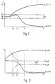
- FIG. 2 shows a diagram of the resulting voltage U A as a function of the temperature of the oxygen probe for the rich and lean branch (lambda ⁇ 1, lambda> 1)
- FIG. 3 Diagram of the electromotive force U of the oxygen probe as a function of the temperature for the rich and lean rest
- FIG. H a graph of the electromotive force U s of the oxygen probe as a function of lambda with the temperature T as a parameter.
- 10 is the equivalent circuit diagram of an oxygen probe, as described in detail, for example, in DE-PS 27 07 383.
- the oxygen probe 10 is arranged in an exhaust pipe 12 of an internal combustion engine 13, which receives the operating mixture from a mixture preparation arrangement 14, with which the ratio of fuel 15 to air 16 is determined.
- the oxygen probe 10, which is connected to ground potential on one side, is connected to a voltage source U R via a resistor 17.
- a supply line leads from the connection point of the resistors 11, 17 to the non-inverting input of a comparison device 18 and to the inverting input of a comparison device 19.
- a threshold voltage voltage U 0 is applied to the inverting input of the comparison device 18, while a threshold value voltage U is applied to the non-inverting input of the comparison device 19 u is supplied.
- the output variables of these two comparison devices 18, 19 control a probe state detection device 20, which in turn actuates a device symbolically referred to here as a switch 21, with which the control circuit is interrupted and switched to a control when the oxygen probe is not ready for operation.
- the output variable of the comparison device 18 is also fed to a control device 22 which in turn controls the mixture preparation arrangement 14 via the switch 21.
- a common dimensioning of the threshold value voltages U 0 , U u is to place them symmetrically with respect to the reference voltage U R , so that the two threshold values are separated by a voltage difference ⁇ U.
- the control device 22 can, as indicated by the dashed arrows, be influenced by further machine parameters such as load L, temperature v or speed n.
- the device described in FIG. 1 functions as follows: For voltages U A above the threshold value U 0 , the control device 22 regulates the gasoline mixture in the direction of lean values. However, the voltage U takes values between the upper threshold value and the lower threshold value, the control device 22 regulates the composition of the gasoline-air mixture in the direction of rich values. If the voltage U A is still in this window between the two threshold values after a monitoring time has elapsed, the probe state detection device 20 detects that the probe is not ready for operation and the switch 21 is actuated, so that a switch is made to a controller. If the control mode is switched for values U A below the lower threshold value U u , the control device 22 regulates the composition of the gasoline mixture in the rich direction.
- the running direction of the control device 22 is thus only dependent on the position of the voltage U A in relation to the upper threshold value U 0 , which is why this threshold value is also referred to as the control threshold.
- this threshold value is also referred to as the control threshold.
- the control device is adjusted Expiry of a monitoring time switched over to control, in which case a rich operating mixture is usually aimed at.
- the comparison device 18 switches (there is a rich operating mixture in the control), the probe status detection device 20 determines operational readiness, switches from control to regulation and the control device 22 regulates the operating mixture in the lean direction.
- the composition of the operating mixture is again adjusted in the bold direction by the control device.
- Appropriate dimensioning of the arrangement makes it possible for the voltage U A to exceed the upper threshold value U 0 again before the monitoring time has expired has stepped and the control remains switched on. In this way, the so-called “idle sawing", as described for example in the application P 31 49 136.7, is avoided.
- FIG. 1 A voltage as a function of the temperature is also plotted in this diagram, which are now the two branches of the electromotive force U S of the oxygen probe 10.
- the influence of the strongly temperature-dependent internal resistance 11 of the oxygen probe is initially neglected in this illustration.
- the internal resistance 11 was taken into account for this in the effective switching thresholds designated U 0, eff and U U, eff , which are defined as the electromotive force U s of the oxygen probe 10, which is necessary for U A to reach the threshold values U 0 , U U . It can be seen from FIG.
- FIG. 4 shows the electromotive force U S of the oxygen probe as a function of lambda.
- the three different curves apply to temperatures T 3 , T 2 and T 1 . If one carries in this diagram 4 the course of the effective switching threshold U 0, eff , the lambda value varies over the temperature range T 3 to T 1 from ⁇ Max1 to ⁇ Min . Instead, the lower effective control threshold U U, eff increased by the value ⁇ .
- U in the diagram in FIG. 4 there is no difference for high temperatures, as is also to be expected. For lower temperatures, however, a significantly higher variation of the lambda value from ⁇ Max2 to ⁇ Min occurs over the same temperature range T 3 to T 1 .
- each type of mixture preparation arrangement 14 e.g. for controlled or regulated carburettors or for injection, be it continuous or clocked.
Landscapes
- Engineering & Computer Science (AREA)
- Chemical & Material Sciences (AREA)
- Combustion & Propulsion (AREA)
- Mechanical Engineering (AREA)
- General Engineering & Computer Science (AREA)
- Electrical Control Of Air Or Fuel Supplied To Internal-Combustion Engine (AREA)
- Combined Controls Of Internal Combustion Engines (AREA)
Applications Claiming Priority (2)
| Application Number | Priority Date | Filing Date | Title |
|---|---|---|---|
| DE3319432 | 1983-05-28 | ||
| DE19833319432 DE3319432A1 (de) | 1983-05-28 | 1983-05-28 | Verfahren und einrichtung zur regelung des betriebsgemisches einer brennkraftmaschine |
Publications (2)
| Publication Number | Publication Date |
|---|---|
| EP0126953A2 true EP0126953A2 (fr) | 1984-12-05 |
| EP0126953A3 EP0126953A3 (fr) | 1986-03-19 |
Family
ID=6200137
Family Applications (1)
| Application Number | Title | Priority Date | Filing Date |
|---|---|---|---|
| EP84104396A Withdrawn EP0126953A3 (fr) | 1983-05-28 | 1984-04-18 | Procédé et dispositif de commande du mélange air/combustible fourni à un moteur |
Country Status (4)
| Country | Link |
|---|---|
| US (1) | US4528957A (fr) |
| EP (1) | EP0126953A3 (fr) |
| JP (1) | JPS59226253A (fr) |
| DE (1) | DE3319432A1 (fr) |
Cited By (3)
| Publication number | Priority date | Publication date | Assignee | Title |
|---|---|---|---|---|
| EP0640756B1 (fr) * | 1993-08-31 | 1999-12-08 | Yamaha Hatsudoki Kabushiki Kaisha | Dispositif de correction du mélange pour moteurs à gaz |
| EP1467068A1 (fr) * | 2003-04-12 | 2004-10-13 | Audi Ag | Procédé et dispositif de surveillance d'un variateur de levée de soupapes d'un moteur à combustion interne |
| CN109946083A (zh) * | 2019-03-29 | 2019-06-28 | 吉林化工学院 | 一种航空发动机燃油调节器故障诊断设备 |
Families Citing this family (19)
| Publication number | Priority date | Publication date | Assignee | Title |
|---|---|---|---|---|
| JPS6131640A (ja) * | 1984-07-23 | 1986-02-14 | Nippon Soken Inc | 空燃比制御装置 |
| JPH065217B2 (ja) * | 1985-03-07 | 1994-01-19 | 日産自動車株式会社 | 空燃比制御装置 |
| DE3531766C1 (de) * | 1985-09-06 | 1989-07-20 | Honsberg Gmbh Geb | Spannvorrichtung fuer Werkstuecke |
| DE3727573A1 (de) * | 1987-08-19 | 1989-03-02 | Bosch Gmbh Robert | Verfahren und einrichtung zur warmlauf-, vollast- und magerregelung einer brennkraftmaschine bei vorgegebenem lambda-wert |
| JP2600208B2 (ja) * | 1987-10-20 | 1997-04-16 | トヨタ自動車株式会社 | 内燃機関の空燃比制御装置 |
| US4970858A (en) * | 1988-03-30 | 1990-11-20 | Toyota Jidosha Kabushiki Kaisha | Air-fuel ratio feedback system having improved activation determination for air-fuel ratio sensor |
| DE3813219A1 (de) * | 1988-04-20 | 1989-11-02 | Bosch Gmbh Robert | Verfahren und vorrichtung zur lambdaregelung |
| DE3839634A1 (de) * | 1988-11-24 | 1990-05-31 | Bosch Gmbh Robert | Verfahren und vorrichtung zum festlegen mindestens einer schwellspannung bei lambda-eins-regelung |
| DE3840148A1 (de) * | 1988-11-29 | 1990-05-31 | Bosch Gmbh Robert | Verfahren und vorrichtung zum erkennen eines fehlerzustandes einer lambdasonde |
| JP2704991B2 (ja) * | 1989-09-12 | 1998-01-26 | 本田技研工業株式会社 | ヒータ付排気濃度センサの活性化判別方法 |
| US5337722A (en) * | 1992-04-16 | 1994-08-16 | Yamaha Hatsudoki Kabushiki Kaisha | Fuel control and feed system for gas fueled engine |
| JP3139592B2 (ja) * | 1993-08-31 | 2001-03-05 | ヤマハ発動機株式会社 | ガス燃料エンジンの混合気形成装置 |
| US5575266A (en) * | 1993-08-31 | 1996-11-19 | Yamaha Hatsudoki Kabushiki Kaisha | Method of operating gaseous fueled engine |
| JPH07253049A (ja) * | 1994-03-14 | 1995-10-03 | Yamaha Motor Co Ltd | 気体燃料エンジン用燃料供給装置 |
| JPH07253048A (ja) * | 1994-03-15 | 1995-10-03 | Yamaha Motor Co Ltd | ガス燃料エンジンの混合気形成方法及び装置 |
| DE19743644C2 (de) * | 1997-10-02 | 1999-12-16 | Bosch Gmbh Robert | Verfahren zum Betrieb eines Gassensors |
| US6176224B1 (en) | 1998-03-30 | 2001-01-23 | Caterpillar Inc. | Method of operating an internal combustion engine which uses a low energy gaseous fuel |
| US6250292B1 (en) * | 2000-03-06 | 2001-06-26 | Brunswick Corporation | Method of controlling an engine with a pseudo throttle position sensor value |
| JP2012251795A (ja) * | 2011-05-31 | 2012-12-20 | Yamaha Motor Co Ltd | 酸素センサの活性判定システム |
Family Cites Families (5)
| Publication number | Priority date | Publication date | Assignee | Title |
|---|---|---|---|---|
| JPS52114823A (en) * | 1976-03-24 | 1977-09-27 | Nissan Motor Co Ltd | Air fuel ratio controller |
| DE2707383C2 (de) * | 1977-02-21 | 1982-12-02 | Robert Bosch Gmbh, 7000 Stuttgart | Verfahren und Vorrichtung zur Überwachung der Betriebsbereitschaft einer Sauerstoffsonde (λ-Sonde) |
| JPS54162021A (en) * | 1978-06-13 | 1979-12-22 | Nissan Motor Co Ltd | Air fuel ratio controller |
| DE2919220A1 (de) * | 1979-05-12 | 1980-11-27 | Bosch Gmbh Robert | Verfahren zur regelung des kraftstoff/luftverhaeltnisses bei brennkraftmaschinen |
| DE3024607A1 (de) * | 1980-06-28 | 1982-02-04 | Robert Bosch Gmbh, 7000 Stuttgart | Einrichtung zur regelung des kraftstoff/luftverhaeltnisses bei brennkraftmaschinen |
-
1983
- 1983-05-28 DE DE19833319432 patent/DE3319432A1/de not_active Withdrawn
-
1984
- 1984-04-18 EP EP84104396A patent/EP0126953A3/fr not_active Withdrawn
- 1984-05-14 US US06/610,108 patent/US4528957A/en not_active Expired - Lifetime
- 1984-05-16 JP JP59096713A patent/JPS59226253A/ja active Pending
Cited By (4)
| Publication number | Priority date | Publication date | Assignee | Title |
|---|---|---|---|---|
| EP0640756B1 (fr) * | 1993-08-31 | 1999-12-08 | Yamaha Hatsudoki Kabushiki Kaisha | Dispositif de correction du mélange pour moteurs à gaz |
| EP1467068A1 (fr) * | 2003-04-12 | 2004-10-13 | Audi Ag | Procédé et dispositif de surveillance d'un variateur de levée de soupapes d'un moteur à combustion interne |
| CN109946083A (zh) * | 2019-03-29 | 2019-06-28 | 吉林化工学院 | 一种航空发动机燃油调节器故障诊断设备 |
| CN109946083B (zh) * | 2019-03-29 | 2021-03-05 | 吉林化工学院 | 一种航空发动机燃油调节器故障诊断设备 |
Also Published As
| Publication number | Publication date |
|---|---|
| EP0126953A3 (fr) | 1986-03-19 |
| JPS59226253A (ja) | 1984-12-19 |
| DE3319432A1 (de) | 1984-11-29 |
| US4528957A (en) | 1985-07-16 |
Similar Documents
| Publication | Publication Date | Title |
|---|---|---|
| EP0126953A2 (fr) | Procédé et dispositif de commande du mélange air/combustible fourni à un moteur | |
| DE3149136C2 (fr) | ||
| DE2702863C2 (de) | Verfahren und Vorrichtung zur Regelung der Gemischverhältnisanteile des einer Brennkraftmaschine zugeführten Betriebsgemischs | |
| DE2413227C3 (de) | Regeleinrichtung für das Luft-Brennstoff-Mischungsverhältnis einer Brennkraftmaschine | |
| DE3812289C2 (de) | Leerlaufdrehzahlregelvorrichtung für eine Brennkraftmaschine | |
| DE2648478C2 (de) | Verfahren und Vorrichtung zum Regeln des Luft/Kraftstoffverhältnisses einer mit einem Abgasfühler ausgerüsteten Brennkraftmaschine | |
| DE3500594A1 (de) | Zumesssystem fuer eine brennkraftmaschine zur beeinflussung des betriebsgemisches | |
| DE2924649A1 (de) | Regelungssystem zur regelung des luft/brennstoff-verhaeltnisses einer verbrennungskraftmaschine | |
| DE2919220C2 (fr) | ||
| EP1583958A1 (fr) | Circuiterie pour faire fonctionner un capteur de gaz | |
| EP0142011A2 (fr) | Appareil pour déterminer la composition du mélange dans un moteur à combustion | |
| EP0042914B1 (fr) | Dispositif de régulation du rapport air/carburant pour moteurs à combustion interne | |
| EP0157004B1 (fr) | Système de régulation du "lambda" du mélange pour moteur à combustion interne | |
| DE4024212C2 (de) | Verfahren zur stetigen Lambdaregelung einer Brennkraftmaschine mit Katalysator | |
| DE2617527A1 (de) | Regelsystem fuer das luft-brennstoff-gemisch eines inneren verbrennungsmotors | |
| DE2750478C2 (de) | Einrichtung zur Korrektur der Ausgangsspannungskennlinie einer Sauerstoffmeßsonde mit einem ionenleitenden Festelektrolyten | |
| DE3214059A1 (de) | Kraftstoffzumesssystem fuer eine brennkraftmaschine | |
| DE3139988C2 (fr) | ||
| DE2949380A1 (de) | Brennstoff/luft-verhaeltnis-regeleinrichtung | |
| DE3327156A1 (de) | Verfahren und vorrichtung zur (lambda)-regelung des kraftstoffgemisches fuer eine brennkraftmaschine | |
| DE3024606A1 (de) | Regeleinrichtung fuer die zusammensetzung des in einer brennkraftmaschine zur verbrennung kommenden betriebsgemisches | |
| DE102004050092B3 (de) | Verfahren zur Regelung des Lambda-Wertes einer Brennkraftmaschine | |
| DE3149096A1 (de) | Verfahren zur lambda-regelung bei einer brennkraftmaschine sowie entsprechendes regelsystem | |
| DE4434465C2 (de) | Gemischregler für einen Verbrennungsmotor | |
| DE3630847C2 (fr) |
Legal Events
| Date | Code | Title | Description |
|---|---|---|---|
| PUAI | Public reference made under article 153(3) epc to a published international application that has entered the european phase |
Free format text: ORIGINAL CODE: 0009012 |
|
| 17P | Request for examination filed |
Effective date: 19840418 |
|
| AK | Designated contracting states |
Designated state(s): DE FR GB IT |
|
| PUAL | Search report despatched |
Free format text: ORIGINAL CODE: 0009013 |
|
| RHK1 | Main classification (correction) |
Ipc: F02D 41/06 |
|
| AK | Designated contracting states |
Kind code of ref document: A3 Designated state(s): DE FR GB IT |
|
| STAA | Information on the status of an ep patent application or granted ep patent |
Free format text: STATUS: THE APPLICATION HAS BEEN WITHDRAWN |
|
| 18W | Application withdrawn |
Withdrawal date: 19860809 |
|
| RIN1 | Information on inventor provided before grant (corrected) |
Inventor name: REISCHL, ROLF Inventor name: JUNDT, WERNER, DIPL.-ING. |