EP0127070A2 - Un ensemble d'habitation transportable de capacité variable - Google Patents
Un ensemble d'habitation transportable de capacité variable Download PDFInfo
- Publication number
- EP0127070A2 EP0127070A2 EP84105575A EP84105575A EP0127070A2 EP 0127070 A2 EP0127070 A2 EP 0127070A2 EP 84105575 A EP84105575 A EP 84105575A EP 84105575 A EP84105575 A EP 84105575A EP 0127070 A2 EP0127070 A2 EP 0127070A2
- Authority
- EP
- European Patent Office
- Prior art keywords
- inhabitative
- unit
- base body
- paneling
- sections
- Prior art date
- Legal status (The legal status is an assumption and is not a legal conclusion. Google has not performed a legal analysis and makes no representation as to the accuracy of the status listed.)
- Withdrawn
Links
Images


Classifications
-
- E—FIXED CONSTRUCTIONS
- E04—BUILDING
- E04B—GENERAL BUILDING CONSTRUCTIONS; WALLS, e.g. PARTITIONS; ROOFS; FLOORS; CEILINGS; INSULATION OR OTHER PROTECTION OF BUILDINGS
- E04B1/00—Constructions in general; Structures which are not restricted either to walls, e.g. partitions, or floors or ceilings or roofs
- E04B1/343—Structures characterised by movable, separable, or collapsible parts, e.g. for transport
- E04B1/344—Structures characterised by movable, separable, or collapsible parts, e.g. for transport with hinged parts
- E04B1/3442—Structures characterised by movable, separable, or collapsible parts, e.g. for transport with hinged parts folding out from a core cell
Definitions
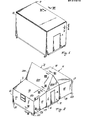
- This invention relates to an inhabitative unit, particularly provided for rapid and temporarily realizations such as, for example, in occasion of earthquakes, floods and the like, capable of assuming for transportation a reduced floor space and at the site of use a substantially larger volume or capacity, by using component parts contained within the reduced floor space taken for transportation and without resorting to specialized labour and particular implements and tools of unusual availability.
- a transportable inhabitative unit which is essentially characterized by comprising a base body, provided with an extensible pedestal, on the extension of which at least one additional body can be built, this additional body comprising wall components connected with the base body and mutually engaging to stabilize such an additional body.
- the inhabitative may assume two high different volumetrically forms, one of which compact of minor volume, referred to as base body R, at which it is transported, for example on railway car, truck, semitrailer or the like, shown in Fig. 1, and the other of a larger volume at the site of use and shown in Fig. 2.
- the inhabitative unit includes a pedestal shown in Fig. 8, comprising two metal longitudinal members having uprights or stanchions 2 welded to the ends thereof.
- the two uprights or stanchions of a same longitudinal member are joined at the top by longitudinal beams 3, of which one is partly shown in Fig. 3.
- two reactangular, vertical and parallel frames are obtained as contained within the planes of the two longitudinal members 1 .
- Said two frames are joined at the ends by metal crosspieces 4 and uprights or stanchions 5 and, at the lower side thereof, by pairs of transverse sections 6, 7 of reactangular section, arranged and welded in seats 8 in said longitudinal members 1.
- threaded bushes 9 are welded, having arranged therein threaded pins 10, at the bottom carrying bearing plates 11, for example by means of any known articulations.
- the two side frames 1, 2, 3 with the crosspieces 4, 6, 7 and uprights or stanchions 5 specify the resistant carrying structure of the inhabitative unit in its compact form shown in Fig. 1.
- Such a structure has connected thereto panelings, provided with passages and casings A, and defining a floor B, ceiling C, front walls E and side walls D of such a compact body.
- the solidarization is committed to any known means, such as screws, sections, expansible sliding blocks, clamps and the like.
- transverse holes 23 are provided both in said sections 6, 7 and beams 6A, 7A for insertion of simple spikes or stop pins.
- a resilient sealing element 30 is provided surrounding as a band the contour of ceiling C, to which it is secured, for example by means of screws.
- This paneling may be made in any known manner, for example in the form of monolythic sandwich structure, formed of external lining plates and an intermediate insulating layer, for example a foamed synthetic material, or a foamed wood composite material.
- the paneling 18 of rectangular shape is defined on the three remaining contour sides (the fourth side is that of the above mentioned hinge 29) by a section 35 provided with wings or flanges 36, by which it is secured, for example embedded in the paneling material.
- the section has a flat cantilevered side or flank 37 terminating with a wing or flange 38 bent over to the panel, and forming with said side or flank 37 an acute angle and on the contour provided with an enlargement 39 and web 40.
- a groove 41 at the attachment zone of wing or flange 38 promotes the elastic deflection of the latter.
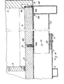
- the second paneling is that forming the floor 19 of the additional bodies X and Y, floor which bears on the beams 6A, 7A of the pedestal extensions and which (as shown in Fig. 4) is connected by double hinge or double articulation 38A, B to the slightly- re-entering edge 39 of floor B.
- said section 19 On its two parallel side edges, said section 19 has a section 35A quite identical to section 35 of paneling 1 8.
- its lower face has secured thereto inclined planes 500 acting to the end against the inner upper corner 501 of the longitudinal member 6B, 7B.
- V V V The third paneling, denoted at 17 and made as above described, is joined by double hinge 50, 51, as shown in Fig. 4, to the outer edge of paneling 19 and on three sides (the fourth side is that of the double hing 50, 51) it has a contour section 35B quite similar (see Fig. 5) to that above described in connection with paneling 18, but facing (Fig. 5) with its angled side or flank 38B to the above described panelings 18 and 19.
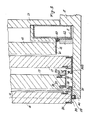
- Panelings 16 are secured to uprights or stanchions 2 and form the front walls (see Fig. 2) of the additional bodies X and Y.
- said panelings 16 are pivoted on vertical axes 60 at a ver - tical edge thereof, and in order to assure sealing at this edge thereof, denoted at 61, the front wall E of the base body and upright or stanchion have secured thereto a resilient sealing strip 62.
- said paneling 16 On the remaining three sides, that is on the upper, lower and end sides, said paneling 16 also has (see Fig.3) a contour defined by sections 35C, D, which are formally but not substantially different from those described in connection with the preceding panelings. Particularly, referring to the positions taken in said Fig. 3, said section 35C has vertically at the top a groove 70 for receiving a resilient sealing strip 71.
- said section 35C Laterally of said channel or groove 70 and particularly on the side or flank 72 of the latter, said section 35C has an outwardly inclined wing or flange 73 substantially coincident with flanges or wings 38 of the above described sections.
- the enlarged edged 39 of the inclined wings or flanges 37 and 73 can snap interengage by elastic deformation when paneling 16 is rotated about the horizontal axis 60 and moved to its closed position of Figs. 2 and 3.
- Snap engagement also occurs at the vertical side (not shown) between the section on the vertical side of paneling 16 and equivalent section on side paneling 17.
- gaskets 80 are inserted in the sections to create sealing borders and labyrinths.
- the lower section 35D or pneling 16 which, as shown, is intended for snap engagement with section 35A of base paneling 19, has a downward facing can- ti l evered wing or flange 101, substantially parallel to paneling 16, and an inclined wing or flange 102 provided with enlarged edge 103 in opposite direction to that of section 35A of paneling 19.
- the side walls 16 snap engage along the three free sides respectively with the ceiling 18 of the two additional bodies X and Y, the two sides of floor 19, and the two vertical sides of the outer wall 17, which also snap engages along line 120 of Fig. 2 with the section extending along the corresponding side of ceiling 18 and which corresponds as drawing to that 35 and is also a continuation thereof.
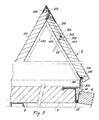
- the inhabitative unit comprises a third additional body, denoted at Z, superposed to the original base body R and also formed with structural elements (panelings) integral with said base body.
- This body Z comprises two identical substantially triangular heads 200 and two laps 201, 202.
- the lap 201 (see Fig. 6) also formed of a layered panel, is connected to ceiling C of the base body by a double hinge 203, 204, the end arms 205n 206 of which are respectively secured by screws, pins or the like to said lap and ceiling C, to the latter by means of brackets 207 terminating embedded in the material of the ceiling.
- the pivoting pin 204 enters a groove or seat 210 of the lap, which at a closer distance from the edge, has a similar groove 211 to receive at erected lap the other pivoting pin 203.
- said lap 201 is undercut to be received in a top chamel-like section 220, having mounted therein an elastic linear gasket of triangular section.
- This latter lap, at collapsed position (see Fig. 6) is interposed between lap 201 and said two triangular heads 200, which obviously are of such a height as not to be superposed to each other, that is such as to be contained within a same plane.
- the lap 202 is hinged at 230 to the end of a bracket 231 embedded in and projecting from ceiling C.
- the hinge 230 is arranged within a groove 232 of the lap and located above the upper edge of the sealing band 30, the side or flank 30A of which is, as shown in Figs. 6 and 7, approximately of the same thickness as that of a triangular head 200 and defines a room or opening in which the two heads are received.
- a pin 310 (Fig. 7) is slidably arranged in the latter and operable by a lever 311 pivoted at 312 to the wall and provided with a fork 313, in which a cross pin 314 is arranged as placed in the catch 310.
- This catch 310 is intended to enter an aligned seat 315 in the other lap 201.
- sections of the type as sections 35A, B, C, D described in connection with Fig. 5, are arranged along the two parallel edges of the laps.
- these sections are such as to allow snap coupling with similar sections provided on adjoining edges of the other panelings.
- Fig. 9 shows on enlarged scale the connection between a side wall 16 and floor 19, that is what already shown at the right lower part of Fig. 3.
- This Fig. 9 has the purpose of showing how snap engagement occurs between the metal (aluminum) sections defining the adjoining edges not only of panelings 16 and 19, but also of the other panelings comprising the additional bodies X, Y, Z.
- section 35A has as an extension of the edge of floor 19 a wing or flange 37A, involved by a groove 41A adjacent an attachment location of a side or flange 38A forming an acute angle with wing or flange 37A.
- inclined side or flank 38A has an enlargement 39A defined by an arcuate surface 79 followed by a step S and a longitudinal web or strip 40A.
- the section 35D has in continuation of its supportw wall 16 a wing or flange 101, followed under acute angle by an inclined wing or side 102 terminating with an enlargement 103 provided with arcuate surface 79 and gaving a step T and a web or strip 103A.
- each of the sections there is also provided a projection or wedge-like web 500, the function of which is to restrict the inclination or deflection of the inclined sides or flanks 38A and 102 when the two sections engage, and to retain in loco the resilient gaskets, here denoted at P and 0, which are inserted in the respective sections before the interengagement and which, upon engagement, owing to the intrinsic elasticity thereof fit with the surfaces with which they are in contact.
- the arcuate surfaces 79A and 79 interfere with each other and cause the elastic deflection of the respective wings or glanges 38A, 102 to the level of steps S, when the two inclined wings or flanges 38A, 102 snap one behind the other forcibly and steadily connecting the sections and accordingly the panlings to one another.
- the arcuate surfaces 79A and 79 interfere with each other and cause the elastic deflection of the respective wings or glanges 38A, 102 to the level of steps S, when the two inclined wings or flanges 38A, 102 snap one behind the other forcibly and steadily connecting the sections and accordingly the panlings to one another.
- fingers 700 For further stabilization of the structures upon erection, use can be made of fingers 700 (see Fig. 9) turnable by a square wrench, which fingers inserti in openings 701 in sections 35A, B in interengagement. Rotation occurs in a plane perpendicular to that of Fig. 9.
- the erection of additional body Z is provided by first rotating said lap 201 in conterclockwise direction and then lap 202 in clockwise direction, engaging the former in the ridge channel 220 of the latter and then operating the catch 310 for steadily restraining the two laps to each other. Then, the heads are rotated about the horizontal pivoting axes thereof, which heads 200 bring the contour sections thereof in engagement with those along the side edges of the laps.
- sum- marizin g consists of first rotating in clockwise direction the ceiling 18 and then in counterclockwise direction the assembly comprising the floor 19 and side or flank 17, the latter being then rotated again in counterclockwise direction and engaged by its upper section with the extreme section of ceiling 18.
- the two heads 16 of the additional bodies are rotated about the horizontal axes 60, engaging the sections thereof, extending on three sides, with the corresponding sections of ceiling 18, side or flank 17 and floor 19.
- said longitudinal beams 6B, 7B have upward directed wings or flanges, thus acting as containing sides or flanks for the outermost paneling 18 and hence also for the innermost remaining panelings.
- the base body may be a rectangular frame 900, in the opening 901 of which are arranged the various panelings 902 made, arranged and connected as above described and shown in the preceding figures of the drawings.
- the base frame 903 comprising on two sides two arms 904 rotatable about vertical axes 905 coincident, for example, with those of the bearing feet 906.
- the Base frame is completed by a longitudinal member 907 forming part of floor 908 of the additional body shown by thin lines in the associated figure.
Landscapes
- Engineering & Computer Science (AREA)
- Architecture (AREA)
- Physics & Mathematics (AREA)
- Electromagnetism (AREA)
- Civil Engineering (AREA)
- Structural Engineering (AREA)
- Revetment (AREA)
- Joining Of Building Structures In Genera (AREA)
Applications Claiming Priority (2)
| Application Number | Priority Date | Filing Date | Title |
|---|---|---|---|
| IT213783 | 1983-05-31 | ||
| IT213783 | 1983-05-31 |
Publications (2)
| Publication Number | Publication Date |
|---|---|
| EP0127070A2 true EP0127070A2 (fr) | 1984-12-05 |
| EP0127070A3 EP0127070A3 (fr) | 1985-10-02 |
Family
ID=11102741
Family Applications (1)
| Application Number | Title | Priority Date | Filing Date |
|---|---|---|---|
| EP84105575A Withdrawn EP0127070A3 (fr) | 1983-05-31 | 1984-05-16 | Un ensemble d'habitation transportable de capacité variable |
Country Status (1)
| Country | Link |
|---|---|
| EP (1) | EP0127070A3 (fr) |
Cited By (9)
| Publication number | Priority date | Publication date | Assignee | Title |
|---|---|---|---|---|
| GB2217358A (en) * | 1988-04-12 | 1989-10-25 | Guildway Limited | Pitched roof of transportable building |
| US5170901A (en) * | 1988-11-28 | 1992-12-15 | Parteurosa, Societe Anonyme | Transportable construction element in the form of a container |
| WO1998002626A1 (fr) * | 1995-02-03 | 1998-01-22 | Kalinowski J Ramon | Batiment repliable et transportable |
| WO1998017876A1 (fr) * | 1996-10-24 | 1998-04-30 | D.D.C. Planungs- Entwicklungs Und Management Ag | Batiment pourvu d'un toit pouvant basculer |
| WO2013016202A3 (fr) * | 2011-07-22 | 2013-05-02 | Elite Aluminum Corporation | Unité d'abri portable repliable |
| WO2013137837A1 (fr) * | 2012-03-15 | 2013-09-19 | Cicen Ragip | Mécanisme de maison préfabriquée pliable |
| US20130305626A1 (en) * | 2011-05-05 | 2013-11-21 | Rapid Fabrications IP LLC | Collapsible transportable structures and related systems and methods |
| US8720126B2 (en) * | 2012-05-07 | 2014-05-13 | Jack Dempsey Stone & Rapid Fabrications Ip Llc | Transportable, expandable containers and emergency structures for habitat and field use |
| EP2480728A4 (fr) * | 2009-09-23 | 2014-11-05 | Blu Homes Inc | Éléments de bâtiment pliables |
Family Cites Families (10)
| Publication number | Priority date | Publication date | Assignee | Title |
|---|---|---|---|---|
| US2634462A (en) * | 1946-06-15 | 1953-04-14 | Nettie E Graven | Portable folding house construction |
| DE833695C (de) * | 1950-05-27 | 1952-03-10 | Hans Schoenstein | Vorfuehrungsraum, insbesondere fuer Lichtspielzwecke |
| DE1434593A1 (de) * | 1951-01-28 | 1969-09-18 | Clinomobil Hospital Werk Gmbh | Zusammenlegbares,eine Klinikzelle bildendes Haus |
| FR2049301A5 (fr) * | 1969-06-06 | 1971-03-26 | Lecorche Jean | |
| GB1379207A (en) * | 1971-12-22 | 1975-01-02 | Masters Of Beckenham Ltd Minsh | Portable buildings |
| US4155204A (en) * | 1978-03-06 | 1979-05-22 | Prozinski Robert S | Expandable mobile home |
| DE2964550D1 (en) * | 1978-09-29 | 1983-02-24 | Brian Albert Ernest Efde | Mobile refreshment equipment |
| GB2071729A (en) * | 1980-03-18 | 1981-09-23 | Howitt R W | Prefabricated building unit |
| US4312159A (en) * | 1980-03-20 | 1982-01-26 | Paul William A | Support for trailer tip outs |
| GB2077321A (en) * | 1980-05-29 | 1981-12-16 | Cuthbert James David Rollo | Cabin building |
-
1984
- 1984-05-16 EP EP84105575A patent/EP0127070A3/fr not_active Withdrawn
Cited By (11)
| Publication number | Priority date | Publication date | Assignee | Title |
|---|---|---|---|---|
| GB2217358A (en) * | 1988-04-12 | 1989-10-25 | Guildway Limited | Pitched roof of transportable building |
| US5170901A (en) * | 1988-11-28 | 1992-12-15 | Parteurosa, Societe Anonyme | Transportable construction element in the form of a container |
| WO1998002626A1 (fr) * | 1995-02-03 | 1998-01-22 | Kalinowski J Ramon | Batiment repliable et transportable |
| WO1998017876A1 (fr) * | 1996-10-24 | 1998-04-30 | D.D.C. Planungs- Entwicklungs Und Management Ag | Batiment pourvu d'un toit pouvant basculer |
| EP2480728A4 (fr) * | 2009-09-23 | 2014-11-05 | Blu Homes Inc | Éléments de bâtiment pliables |
| US20130305626A1 (en) * | 2011-05-05 | 2013-11-21 | Rapid Fabrications IP LLC | Collapsible transportable structures and related systems and methods |
| US9085890B2 (en) | 2011-05-05 | 2015-07-21 | Rapid Fabrications IP LLC | Collapsible transportable structures and related systems and methods |
| WO2013016202A3 (fr) * | 2011-07-22 | 2013-05-02 | Elite Aluminum Corporation | Unité d'abri portable repliable |
| US9187894B2 (en) | 2011-07-22 | 2015-11-17 | Elite Aluminum Corporation | Collapsible portable shelter unit |
| WO2013137837A1 (fr) * | 2012-03-15 | 2013-09-19 | Cicen Ragip | Mécanisme de maison préfabriquée pliable |
| US8720126B2 (en) * | 2012-05-07 | 2014-05-13 | Jack Dempsey Stone & Rapid Fabrications Ip Llc | Transportable, expandable containers and emergency structures for habitat and field use |
Also Published As
| Publication number | Publication date |
|---|---|
| EP0127070A3 (fr) | 1985-10-02 |
Similar Documents
| Publication | Publication Date | Title |
|---|---|---|
| US4986041A (en) | Prefabricated elevator shaft modules | |
| US3784043A (en) | Lightweight collapsible structures | |
| JPH0322593A (ja) | 電気的スイッチ装置用キャビネット | |
| EP0127070A2 (fr) | Un ensemble d'habitation transportable de capacité variable | |
| KR890010378A (ko) | 건물 및 그의 조립식부품과 관련건축방법 | |
| US2208010A (en) | Portable and sectional building construction | |
| JPH01309870A (ja) | 鉄道車両の車体 | |
| US4004373A (en) | Extrusions for partitions, walls and enclosures | |
| EP0792231A1 (fr) | Structure de longeron et de carrosserie de vehicule | |
| JP3219370B2 (ja) | 部材の結合構造 | |
| JP2002201741A (ja) | 間仕切パネルシステム | |
| DE2814089A1 (de) | Kuehlcontainer | |
| JP2007170150A (ja) | 切妻屋根を備えた折畳み構造物 | |
| JPH0319529Y2 (fr) | ||
| JP2859813B2 (ja) | 間仕切における壁パネルの接合構造 | |
| JPS59228544A (ja) | 可変容積型可搬居住ユニツト | |
| RU2046895C1 (ru) | Сборно-разборное здание | |
| JP2817630B2 (ja) | 間仕切パネルの支持装置 | |
| JPH08177128A (ja) | 拡張ユニットの取付構造 | |
| JP2693823B2 (ja) | 面取建物ユニット | |
| JPS61109845A (ja) | ノツクダウン式移動建物 | |
| JP2582811Y2 (ja) | 壁パネルの接続構造 | |
| JPH11165795A (ja) | 水槽の組立方法 | |
| WO1987000591A1 (fr) | Systeme de construction a coutures de jonction | |
| JPH0229134Y2 (fr) |
Legal Events
| Date | Code | Title | Description |
|---|---|---|---|
| PUAI | Public reference made under article 153(3) epc to a published international application that has entered the european phase |
Free format text: ORIGINAL CODE: 0009012 |
|
| 17P | Request for examination filed |
Effective date: 19840516 |
|
| AK | Designated contracting states |
Designated state(s): BE CH DE FR GB LI NL SE |
|
| PUAL | Search report despatched |
Free format text: ORIGINAL CODE: 0009013 |
|
| AK | Designated contracting states |
Designated state(s): BE CH DE FR GB LI NL SE |
|
| 17Q | First examination report despatched |
Effective date: 19860619 |
|
| STAA | Information on the status of an ep patent application or granted ep patent |
Free format text: STATUS: THE APPLICATION IS DEEMED TO BE WITHDRAWN |
|
| 18D | Application deemed to be withdrawn |
Effective date: 19861030 |
|
| RIN1 | Information on inventor provided before grant (corrected) |
Inventor name: PILATI, MARCO Inventor name: VOLANI, ARNALDO Inventor name: FRATESCHI, CARLO Inventor name: BACCINI, VINICIO |