EP0127155A1 - Procédé et dispositif pour fermer un récipient avec un couvercle, qui consistent tour les deux en un matériau plastique déformable - Google Patents
Procédé et dispositif pour fermer un récipient avec un couvercle, qui consistent tour les deux en un matériau plastique déformable Download PDFInfo
- Publication number
- EP0127155A1 EP0127155A1 EP84105983A EP84105983A EP0127155A1 EP 0127155 A1 EP0127155 A1 EP 0127155A1 EP 84105983 A EP84105983 A EP 84105983A EP 84105983 A EP84105983 A EP 84105983A EP 0127155 A1 EP0127155 A1 EP 0127155A1
- Authority
- EP
- European Patent Office
- Prior art keywords
- container
- lid
- edge
- frame elements
- flange
- Prior art date
- Legal status (The legal status is an assumption and is not a legal conclusion. Google has not performed a legal analysis and makes no representation as to the accuracy of the status listed.)
- Granted
Links
- 238000000034 method Methods 0.000 title claims abstract description 19
- 239000000463 material Substances 0.000 title claims abstract description 7
- 238000003825 pressing Methods 0.000 claims abstract description 36
- 238000006073 displacement reaction Methods 0.000 claims abstract description 7
- 230000007935 neutral effect Effects 0.000 claims abstract 3
- 238000005452 bending Methods 0.000 claims description 12
- 230000008878 coupling Effects 0.000 claims description 8
- 238000010168 coupling process Methods 0.000 claims description 8
- 238000005859 coupling reaction Methods 0.000 claims description 8
- XAGFODPZIPBFFR-UHFFFAOYSA-N aluminium Chemical compound [Al] XAGFODPZIPBFFR-UHFFFAOYSA-N 0.000 claims description 4
- 229910052782 aluminium Inorganic materials 0.000 claims description 4
- 239000011888 foil Substances 0.000 claims description 4
- 238000012546 transfer Methods 0.000 claims description 4
- 210000003127 knee Anatomy 0.000 claims description 2
- 210000000629 knee joint Anatomy 0.000 claims 1
- 239000005030 aluminium foil Substances 0.000 abstract 1
- 230000000754 repressing effect Effects 0.000 description 4
- 238000011161 development Methods 0.000 description 3
- 230000006378 damage Effects 0.000 description 2
- 238000013461 design Methods 0.000 description 2
- 230000002349 favourable effect Effects 0.000 description 2
- 238000012986 modification Methods 0.000 description 2
- 230000004048 modification Effects 0.000 description 2
- 238000010276 construction Methods 0.000 description 1
- 238000012937 correction Methods 0.000 description 1
- 230000014759 maintenance of location Effects 0.000 description 1
- 239000013641 positive control Substances 0.000 description 1
- 230000000717 retained effect Effects 0.000 description 1
- 238000009420 retrofitting Methods 0.000 description 1
Images


Classifications
-
- B—PERFORMING OPERATIONS; TRANSPORTING
- B65—CONVEYING; PACKING; STORING; HANDLING THIN OR FILAMENTARY MATERIAL
- B65B—MACHINES, APPARATUS OR DEVICES FOR, OR METHODS OF, PACKAGING ARTICLES OR MATERIALS; UNPACKING
- B65B7/00—Closing containers or receptacles after filling
- B65B7/16—Closing semi-rigid or rigid containers or receptacles not deformed by, or not taking-up shape of, contents, e.g. boxes or cartons
- B65B7/28—Closing semi-rigid or rigid containers or receptacles not deformed by, or not taking-up shape of, contents, e.g. boxes or cartons by applying separate preformed closures, e.g. lids, covers
- B65B7/2842—Securing closures on containers
- B65B7/285—Securing closures on containers by deformation of the closure
- B65B7/2857—Securing closures on containers by deformation of the closure and the container rim
Definitions
- the invention relates to a method for closing a container with a lid, the former having a container flange facing outside the container and the latter having a lid edge protruding beyond the container flange, and the container and lid being made of plastically deformable material, preferably aluminum foil, the container either with a lid that is prefabricated, or a flat lid blank inserted on slide rails above the container between one.
- the upper part and a lower part of a closing device brought into contact with the upper part by at least a part of the lid surface with a vertical relative movement of the lower and upper part, the lid edge bent by frame elements mounted horizontally displaceably on the upper part in the direction of the container bottom, bent under the container flange. and is pressed with the container flange.
- the invention further relates to an apparatus for performing the method described above.
- the receptacle for the container is designed here as a stationary support plate which laterally fixes the container bottom and the adjacent part of the lower container wall by means of an upwardly bent edge.
- the upper part and the lower part are both designed to be vertically movable.
- the counter pressure surface is mounted so that it can move vertically within the upper part and is arranged at the beginning of the closing process below the upper part to leave this free. To carry out the closing process, the upper part is lowered until the counter pressure surface lies on the container or the lid.
- the support of the container on its container base requires the precise adjustment of the stroke of the Upper part to prevent the container from being squashed by lowering the upper part too far.
- Another disadvantage is the necessity that the support plate, the lower part, the frame elements and the counter pressure surface have to be replaced when changing to a different type of container.
- this is achieved in that the container is received by a supporting edge of the lower part on the underside of the container flange at least in its inner edge area assigned to the container wall and with at least one part of the lid assigned to at least partial areas of the container flange by vertical movement of the lower part of a zero position past aa the frame elements is brought up to an upper pressing position for contact with the upper part, the lid edge being bent by passing the frame elements, and by moving the frame elements until support of an outer edge area of the container flange including the corresponding partially bent lid edge area the container is held in contact with the upper part, then the container flange from the supporting edge by vertical movement of the lower part past the frame elements in the direction of the lower zero position released and the lid edge by further displacement of the frame elements to a front end position is bent so far that it moved again by pushing the frame elements back to a rear end position up to at least the upper pressing position, the container from the frame elements and continue completely bent in contact with the upper part holding the upper part and pressed with the container f
- the support edge serves both as a receptacle and as a pressure surface, forces which occur when the edge of the cover is bent or bent are absorbed by the support edge and not by the edge of the cover. Deformations in the container flange cannot lead to incorrect bending and bending as before, but are compensated for by the supporting edge.
- the correct bending of the edge of the lid required for a secure closure is promoted in that the supporting edge is lowered again after reaching the upper pressing position for the first time, in order to enable horizontal displacement of the frame elements as far as possible in the direction of the container wall. After the end of the bending of the lid edge and retraction of the frame elements, there is a renewed upward movement of the support edge for pressing the lid edge.
- the container or container flange in contact with the upper part continues during the period in which the supporting edge moves away from the upper part from the frame elements held in systems on the upper part, the transfer from the support edge to the frame elements and back in a "flying" manner.
- DE-OS 31 24 733 discloses a closing device for closing the containers mentioned at the outset, which has a stationary upper part and a vertically movable lower part with an edge-shaped pressure surface assigned to the counterpressure surface in the upper part.
- the closing process takes place in a manner unrelated to the species with an exposed cover, i.e. ' . without positive retention of the lid edge on the top of the container flange by means of the counter pressure surface of the upper part.
- a support plate is provided between the upper and lower part, onto which the container to be closed is placed.
- a horizontally movable one is used to close the container.
- the container can be closed even more securely in that the lid edge with the container flange by moving the lower part up to is pressed into a re-pressing position arranged above the upper pressing position.
- Container flange is released from the support edge by moving the lower part past the frame elements into a central zero position arranged above the lower zero position.
- the object is achieved with respect to the device in that the upper part is designed to be stationary in the vertical direction, the vertically movable lower part has a support edge designed as a receiving and pressure surface for at least the inner edge region of the container flange or the associated lid edge associated with the container wall.
- the design effort of the device according to the invention is reduced by using a lower part, which takes over both the function of the container receptacle and that of the pressure surface.
- a further design simplification results from the fact that only the lower part is designed to be vertically movable.
- the supporting edge is preferably designed in such a way that it lies at least partially against the outer wall of the container. This results in a particularly precise lateral fixation of the container.
- An advantageous development of the invention is. characterized in that the lower part in an upper pressing position for bending the edge of the lid and for applying at least a part of the lid surface assigned to the supporting edge to the counterpressure surface and from the upper pressing position towards the lower zero position for flying takeover of the container and holding it in contact with the upper part and for bending the lid edge through the frame elements and finally again into the upper pressing position with flying takeover of the container in contact with the upper part and released by the frame elements is designed to be movable with the container flange for pressing the edge of the lid.
- the part is favorable to lower the part into a position above the upper pressing position. arranged arranged repressing position to be movable.
- the lower part is advantageously designed to be movable from the upper pressing position to a middle zero position arranged above the lower zero position.
- the lower part and the frame elements are moved by means of a common drive device. This creates the prerequisite for a forced control of the vertically and horizontally movable parts.
- the drive device preferably has a toggle lever, one outer joint of which is connected to the lower part and the other outer joint of which is fixed, the toggle lever extending from an extended one that determines the upper pressing position Position can be moved in one direction up to the respectively deflected position, the position determining the lower zero position and in the other direction up to a deflected position determining the middle zero position MN.
- the supported outer joint of the toggle lever is preferably designed as an eccentric joint.
- the positive control of the frame elements is achieved in a simple manner in that the movement of the toggle lever is transmitted to the frame elements by means of a lever arrangement.
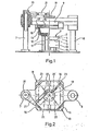
- the closing device comprises a frame with two support columns 7 and 8 arranged opposite one another.
- a fixed upper part 9 is attached to the upper area of the frame connecting the support columns.
- a lower part 10 is arranged, which by means of the bottom or at the bottom Part of the frame supported drive or guide columns 11 is vertically movable.
- the lower part 10 is basket-shaped and has a circumferential wall 13 which extends from the basket bottom 12 upwards and serves as a supporting edge for the container 1.
- the latter is inserted into the lower part 10 in such a way that it is connected to the inner edge region of the container wall 4
- Container flange 5 rests on the top of the support edge 13 -
- the container wall preferably lies at least partially on the inside of the support edge 13 for precise lateral fixing of the container 1.
- the distance between the bottom 12 and the top of the support edge 13 corresponds to the maximum container height in order to be replaced to avoid the lower part 10 when switching to containers of different heights.
- the upper region of the outside of the support edge 13 is designed to be slightly conical in the direction of the inner cavity of the lower part.
- a counter pressure frame 14 having a counter pressure surface is interchangeably arranged on the upper part 9.
- the external dimension of the counter-pressure frame 14 is larger than the external dimension of the lower part 10.
- the area of the counter-pressure frame 14 assigned to the supporting edge has a substantially hemispherical shape.
- the groove 17 is not completely filled by the support edge 13, so that a radially outer part of the groove 17 remains free for receiving the rolled edge 6 of the container 1
- FIG. 2 shows a top view of four frame elements 16, which describe an essentially rectangular area corresponding to the projection of the cavity of the lower part 10.
- Each frame element 16 is in each case assigned to a corner of this area, for this reason it is formed at right angles in the plan view and is displaceably mounted in the diagonal direction of this area by means of longitudinal bearings 18.
- a turntable 19 is arranged above the upper part 9, which is made to oscillate by a pendulum axis 20 which is arranged within the support column 7 in such a way that it can oscillate .
- the turntable 19 is in turn articulated by means of four articulated connecting rods 22 with connecting rods 23, which are arranged within the longitudinal guides 18 and transmit their longitudinal movement to the edge elements 16.
- FIG. 3 shows a drive device 24 common for the vertical movement of the lower part 10 and the horizontal movement of the edge elements 16. It essentially comprises a driven crank 25, which is articulated via a coupling rod 26 to the central joint 27 of a toggle lever 28.
- the level of the toggle lever 28 extends in the direction of movement of the lower part 10.
- the one outer joint 29 of this toggle lever 28 is on the Underside of the outer columns 11 of the lower part 10 articulated.
- the second outer joint 30 facing away from the drive columns 11 is supported in an articulated manner on the frame of the closing device.
- the outer joint 30 is designed as an eccentric joint.
- a lever arrangement 31 is articulated on the lower knee of the toggle lever 28 and in a manner not shown on the pendulum axis 20 in order to transmit the movement of the toggle lever 28 to the pendulum axis 20.
- the axis of rotation 34 of the crank 25 is connected to the eccentric axis 30 via an endless belt or chain drive 35, so that the eccentric axis makes one revolution during one cycle of the crank 25.
- Figure 4 shows the locking tools, i. H. the support edge 13, the counter-pressure frame 14 and one of the frame elements 16 in the open position of the closing device.
- the frame element 16 has assumed the rear end position HE.
- the support edge is in a lower zero position, not shown here.
- the lid edge 32 is in contact with the frame element 16 which is advanced from its rear end position HE in the direction of the support edge 13 and is thereby bent downwards in the direction of the container bottom 3.
- FIG. 6 shows the support edge 13 and the frame element 16 in a position moved further upwards or inwards.
- the lid 2 is just in contact with the counter-pressure frame 14, the rolled edge 6 of the container flange 5 having penetrated so far into the channel 17 that it is located in a plane above the frame element 16.
- the lid edge 32 is already bent vertically downwards.
- the support edge 13 has been moved into an upper pressing position OP, the rolled edge 6 and the inner edge region of the container flange 5 assigned to the container wall 4 and the assigned part of the cover 2 lying against the counter-pressure frame 14 within the channel 17.
- the middle section of the container flange 5 arranged between this inner edge region and the rolled edge and the associated part of the lid 2 are still at a distance from the inside of the channel 17.
- the frame element 16 has already been advanced so far in the direction of the supporting edge 13 that it is already partly under the rolled edge 6 and has partially bent the cover 32.
- Figure 8 shows the support edge 13 in a position below its upper pressing position OB. It is in a downward movement, the rolled edge 6 and thus the container 1 are held by the frame element 16, which is pushed far below the rolled edge 6, in contact with the counter-pressure frame 14 within the channel 17. The transfer of the rolled edge 6 from the support edge 13 to the frame element 16 was "flying"
- FIG. 9 shows the frame element 16 pushed further towards the container 1.
- the support edge 13 is lowered so far that its top is arranged in a plane below the frame element 16.
- the lid edge 32 is bent further under the container flange 5.
- the support edge 13 has reached a middle zero position MN, which is still arranged above its lower zero position UN.
- the frame element 16 is in its front end position VE, in which the lid edge 32 is almost completely bent under the container flange 5 and rests on the container wall.
- Figure 11 shows that the support edge 13 is in a renewed upward movement and the frame element 1.6 is again on the way to its rear end position HE.
- the support edge 13 has reached a repressing position NP, which is arranged above the upper pressing position OP.
- the bent-over edge of the lid 32 is placed on the underside of the container flange 5 and the "pre-closed" container flange, as it were, solidified in accordance with the stroke difference between the upper pressing position OP and the pressing position NP.
- the container flange now lies essentially on the entire inner surface of the channel 17.
- FIG. 14 shows the supporting edge 13 with the container flange 5 lying on it on the way down to the lower zero position UN or the open position of the closing device. This open position is shown in the right half of Figure 2; the container is already lifted out of the lower part 10 by means not shown.
- the drive device 24 is used to carry out the cycle described above.
- the crank 25 rotates.
- the eccentric of the eccentric joint 30 rotates.
- the movement of the crank 25 is transmitted through the coupling rod 26 and via the central joint 27 to the toggle lever 28.
- the toggle lever 28 is in its first deflected position, which corresponds to the lower zero position UN of the lower part 10.
- the toggle lever 28 has reached its extended position, the lower part 10 is in its upper pressing position OP.
- the outer joint 29, as shown in broken lines in FIG. 3 has reached a position above that which corresponds to the aforementioned deflected position of the toggle lever 28.
- the lower part 10 is thus in its middle zero position MN.
- FIG. 15 shows a modification of the toggle lever drive 28 of FIG. 3.
- two pairs of toggle levers 40 and 41 are connected in series.
- the two pairs of toggle levers are connected by a joint 42, which is guided vertically by a sleeve 43 which slides on a rod 44 fixed to the machine.
- a coupling rod 46 engages at the joint 45 of the pair of toggle levers 41, which is connected to a rocker 48 via a joint 47 which is pivotably mounted on the frame frame by means of a joint 49.
- a roller 50 is rotatably attached to the rocker 48 and cooperates with an inner eccentric ring 51.
- a coupling rod 53 acts on the joint 52 of the pair of toggle levers 40, which is connected via a joint 54 to a rocker arm 55 which is pivotably mounted on the machine frame by means of a joint 56.
- a roller 57 is rotatably attached to the rocker 55 and cooperates with an eccentric disk 58.
- the inner eccentric ring 51 rotates continuously together with the eccentric disk 58 about the common axis of rotation 59, the two toggle lever pairs 40 and 41 being brought into an extended position in which the lid edge is pressed together with the container flange.
- the remaining parts of the closing device can be retained
- the drive of the frame elements can also be done separately from the drive of the lower part of the closing device. So it is also possible to drive these parts of the closing device by pressure cylinders. and to control these pressure cylinders through curves or via programs
Landscapes
- Engineering & Computer Science (AREA)
- Mechanical Engineering (AREA)
- Closing Of Containers (AREA)
- Dry Development In Electrophotography (AREA)
- Closures For Containers (AREA)
- Rear-View Mirror Devices That Are Mounted On The Exterior Of The Vehicle (AREA)
- Sealing Devices (AREA)
- Diaphragms And Bellows (AREA)
Priority Applications (1)
| Application Number | Priority Date | Filing Date | Title |
|---|---|---|---|
| AT84105983T ATE24866T1 (de) | 1983-05-27 | 1984-05-25 | Verfahren und vorrichtung zum verschliessen eines behaelters mit einem deckel, welche beide aus plastisch verformbarem material bestehen. |
Applications Claiming Priority (2)
| Application Number | Priority Date | Filing Date | Title |
|---|---|---|---|
| DE3319323 | 1983-05-27 | ||
| DE19833319323 DE3319323A1 (de) | 1983-05-27 | 1983-05-27 | Verfahren und vorrichtung zum verschliessen eines behaelters mit einem deckel, welche beide aus plastisch verformbarem material bestehen |
Publications (2)
| Publication Number | Publication Date |
|---|---|
| EP0127155A1 true EP0127155A1 (fr) | 1984-12-05 |
| EP0127155B1 EP0127155B1 (fr) | 1987-01-14 |
Family
ID=6200068
Family Applications (1)
| Application Number | Title | Priority Date | Filing Date |
|---|---|---|---|
| EP84105983A Expired EP0127155B1 (fr) | 1983-05-27 | 1984-05-25 | Procédé et dispositif pour fermer un récipient avec un couvercle, qui consistent tour les deux en un matériau plastique déformable |
Country Status (5)
| Country | Link |
|---|---|
| EP (1) | EP0127155B1 (fr) |
| AT (1) | ATE24866T1 (fr) |
| DE (2) | DE3319323A1 (fr) |
| DK (1) | DK155182C (fr) |
| NO (1) | NO162552C (fr) |
Cited By (4)
| Publication number | Priority date | Publication date | Assignee | Title |
|---|---|---|---|---|
| US8199571B2 (en) | 2006-03-03 | 2012-06-12 | Sandisk Technologies Inc. | Read operation for non-volatile storage with compensation for coupling |
| US8270217B2 (en) | 2006-04-12 | 2012-09-18 | Sandisk Technologies Inc. | Apparatus for reducing the impact of program disturb |
| US8339855B2 (en) | 2008-06-16 | 2012-12-25 | Sandisk Il Ltd. | Reverse order page writing in flash memories |
| EP2574558A1 (fr) * | 2011-09-30 | 2013-04-03 | Crown Packaging Technology, Inc | Procédé pour la fermeture de boîtes métalliques |
Citations (2)
| Publication number | Priority date | Publication date | Assignee | Title |
|---|---|---|---|---|
| US2704628A (en) * | 1955-03-22 | stanton | ||
| DE3124733A1 (de) * | 1981-06-24 | 1983-01-20 | Gerd 5992 Nachrodt-Wiblingwerde Wachsmuth | Verschliessvorrichtung fuer einwegbehaelter |
Family Cites Families (2)
| Publication number | Priority date | Publication date | Assignee | Title |
|---|---|---|---|---|
| DE2511218C2 (de) * | 1975-03-14 | 1982-12-09 | Hunter Douglas International N.V., Willemstad, Curacao(Niederländische Antillen) | Vorrichtung zum Verschließen eines mit einem waagerechten Randstreifen versehenen Behälters mit einem Deckel |
| DE2935479C3 (de) * | 1979-09-01 | 1982-02-25 | HD-Ekco N.V., Genk | Vorrichtung zum Verschließen eines Behälters mit einem aus plastisch verformbarem Material hergestelltenDeckel. |
-
1983
- 1983-05-27 DE DE19833319323 patent/DE3319323A1/de not_active Withdrawn
-
1984
- 1984-05-23 DK DK253684A patent/DK155182C/da active
- 1984-05-25 NO NO842108A patent/NO162552C/no unknown
- 1984-05-25 AT AT84105983T patent/ATE24866T1/de not_active IP Right Cessation
- 1984-05-25 EP EP84105983A patent/EP0127155B1/fr not_active Expired
- 1984-05-25 DE DE8484105983T patent/DE3462004D1/de not_active Expired
Patent Citations (2)
| Publication number | Priority date | Publication date | Assignee | Title |
|---|---|---|---|---|
| US2704628A (en) * | 1955-03-22 | stanton | ||
| DE3124733A1 (de) * | 1981-06-24 | 1983-01-20 | Gerd 5992 Nachrodt-Wiblingwerde Wachsmuth | Verschliessvorrichtung fuer einwegbehaelter |
Cited By (9)
| Publication number | Priority date | Publication date | Assignee | Title |
|---|---|---|---|---|
| US8199571B2 (en) | 2006-03-03 | 2012-06-12 | Sandisk Technologies Inc. | Read operation for non-volatile storage with compensation for coupling |
| US8427873B2 (en) | 2006-03-03 | 2013-04-23 | Sandisk Technologies Inc. | Read operation for non-volatile storage with compensation for coupling |
| US8270217B2 (en) | 2006-04-12 | 2012-09-18 | Sandisk Technologies Inc. | Apparatus for reducing the impact of program disturb |
| US8331154B2 (en) | 2006-04-12 | 2012-12-11 | Sandisk Technologies Inc. | Apparatus for reducing the impact of program disturb |
| US8542530B2 (en) | 2006-04-12 | 2013-09-24 | Sandisk Technologies Inc. | Apparatus for reducing the impact of program disturb |
| US8593871B2 (en) | 2006-04-12 | 2013-11-26 | Sandisk Technologies Inc. | Apparatus for reducing the impact of program disturb |
| US8339855B2 (en) | 2008-06-16 | 2012-12-25 | Sandisk Il Ltd. | Reverse order page writing in flash memories |
| EP2574558A1 (fr) * | 2011-09-30 | 2013-04-03 | Crown Packaging Technology, Inc | Procédé pour la fermeture de boîtes métalliques |
| WO2013045263A1 (fr) * | 2011-09-30 | 2013-04-04 | Crown Packaging Technology, Inc. | Processus de fermeture de boîtes métalliques |
Also Published As
| Publication number | Publication date |
|---|---|
| DE3319323A1 (de) | 1984-11-29 |
| DE3462004D1 (en) | 1987-02-19 |
| DK253684D0 (da) | 1984-05-23 |
| DK253684A (da) | 1984-11-28 |
| NO162552C (no) | 1990-01-17 |
| NO842108L (no) | 1984-11-28 |
| DK155182C (da) | 1989-07-31 |
| EP0127155B1 (fr) | 1987-01-14 |
| ATE24866T1 (de) | 1987-01-15 |
| DK155182B (da) | 1989-02-27 |
| NO162552B (no) | 1989-10-09 |
Similar Documents
| Publication | Publication Date | Title |
|---|---|---|
| DE69321728T2 (de) | Zweistufiger matritzensatz | |
| DE69101782T2 (de) | Zufuhr- und austauschvorrichtung eines tauchrohres. | |
| DE2142570B2 (de) | Mechanische Pulverpresse, insbesondere Metallpulverpresse | |
| CH641030A5 (de) | Verfahren zur herstellung von kaffee und kaffeemaschine zur ausfuehrung desselben. | |
| DE2256180A1 (de) | Auf eine presse montierbare einrichtung zum lochen | |
| DE2649630A1 (de) | Vorrichtung zum verschliessen und abdichten einer kartonpackung | |
| DE2035467B2 (de) | Vorrichtung zum Formen von inneren Belägen aus thermoplastischem Kunststoff in Verschlußkapseln o.dgl | |
| DE2830849A1 (de) | Verschliessmaschine fuer steckkapseln | |
| DE3042070C2 (fr) | ||
| EP0127155B1 (fr) | Procédé et dispositif pour fermer un récipient avec un couvercle, qui consistent tour les deux en un matériau plastique déformable | |
| DE2251850C3 (de) | Vorrichtung zum Verschließen gefüllter Bördelrandbehälter | |
| DE69127084T2 (de) | Vorrichtung zum Wechseln von Teilen bei Blasformmaschinen | |
| DE2407637A1 (de) | Vorrichtung zum verschliessen von behaeltern | |
| EP0252167A1 (fr) | Machine pour fixer des boutons, rivets ou analogues à des vêtements | |
| DE4016576C2 (de) | Vorrichtung zum aufeinanderfolgenden Entnehmen des jeweils anstehenden Behälters eines Behälterstapels | |
| DE2523517C3 (de) | Vorrichtung zum Eindrücken von Füllgut in oben offene Gefäße und zum Abquetschen und Abscheren von über den Rand der Gefäße überstehendem Füllgut | |
| DE2918429A1 (de) | Ankrempelvorrichtung nach einer einrichtung zur aufbringung einer folie auf einen behaelterrand | |
| EP0241680A1 (fr) | Procédé et dispositif pour fermer des récipients | |
| DE830891C (de) | Behaelterverschlussdeckel aus Papier sowie Verfahren und Maschine zur Herstellung desselben | |
| DE3337683C2 (fr) | ||
| EP0209890B1 (fr) | Dispositif de fermeture de récipients | |
| DE3637854A1 (de) | Vorrichtung zum einbringen von kugeln in die zwischen den beiden ringen eines kugellagers gebildete laufbahn | |
| EP0664171A1 (fr) | Outil pour machines de fermeture | |
| DE1586043C (de) | Vorrichtung zum Verschließen und Abdichten eines Behälters aus Metallfolie | |
| DE360569C (de) | Presse zum Entwaessern oder Brikettieren |
Legal Events
| Date | Code | Title | Description |
|---|---|---|---|
| PUAI | Public reference made under article 153(3) epc to a published international application that has entered the european phase |
Free format text: ORIGINAL CODE: 0009012 |
|
| 17P | Request for examination filed |
Effective date: 19840525 |
|
| AK | Designated contracting states |
Designated state(s): AT BE CH DE FR GB IT LI LU NL SE |
|
| EL | Fr: translation of claims filed | ||
| ITCL | It: translation for ep claims filed |
Representative=s name: JACOBACCI CASETTA & PERANI S.P.A. |
|
| 17Q | First examination report despatched |
Effective date: 19860404 |
|
| GRAA | (expected) grant |
Free format text: ORIGINAL CODE: 0009210 |
|
| AK | Designated contracting states |
Kind code of ref document: B1 Designated state(s): AT BE CH DE FR GB IT LI LU NL SE |
|
| REF | Corresponds to: |
Ref document number: 24866 Country of ref document: AT Date of ref document: 19870115 Kind code of ref document: T |
|
| ITF | It: translation for a ep patent filed | ||
| REF | Corresponds to: |
Ref document number: 3462004 Country of ref document: DE Date of ref document: 19870219 |
|
| ET | Fr: translation filed | ||
| PLBE | No opposition filed within time limit |
Free format text: ORIGINAL CODE: 0009261 |
|
| STAA | Information on the status of an ep patent application or granted ep patent |
Free format text: STATUS: NO OPPOSITION FILED WITHIN TIME LIMIT |
|
| 26N | No opposition filed | ||
| REG | Reference to a national code |
Ref country code: CH Ref legal event code: PFA Free format text: ALCAN DEUTSCHLAND GMBH |
|
| REG | Reference to a national code |
Ref country code: GB Ref legal event code: 732 |
|
| NLS | Nl: assignments of ep-patents |
Owner name: ALCAN ALUMINIUMWERKE GMBH TE GOETTINGEN-WEENDE, BO |
|
| NLT1 | Nl: modifications of names registered in virtue of documents presented to the patent office pursuant to art. 16 a, paragraph 1 |
Owner name: ALCAN DEUTSCHLAND GMBH TE GOETTINGEN, BONDSREPUBLI |
|
| REG | Reference to a national code |
Ref country code: FR Ref legal event code: CD |
|
| REG | Reference to a national code |
Ref country code: FR Ref legal event code: TP |
|
| ITPR | It: changes in ownership of a european patent |
Owner name: CESSIONE;ALCAN DEUTSCHLAND GMBH |
|
| ITTA | It: last paid annual fee | ||
| PGFP | Annual fee paid to national office [announced via postgrant information from national office to epo] |
Ref country code: GB Payment date: 19930422 Year of fee payment: 10 |
|
| PGFP | Annual fee paid to national office [announced via postgrant information from national office to epo] |
Ref country code: SE Payment date: 19930519 Year of fee payment: 10 |
|
| PGFP | Annual fee paid to national office [announced via postgrant information from national office to epo] |
Ref country code: CH Payment date: 19930625 Year of fee payment: 10 |
|
| PG25 | Lapsed in a contracting state [announced via postgrant information from national office to epo] |
Ref country code: GB Effective date: 19940525 |
|
| PG25 | Lapsed in a contracting state [announced via postgrant information from national office to epo] |
Ref country code: SE Effective date: 19940526 |
|
| PG25 | Lapsed in a contracting state [announced via postgrant information from national office to epo] |
Ref country code: LI Effective date: 19940531 Ref country code: CH Effective date: 19940531 |
|
| EPTA | Lu: last paid annual fee | ||
| GBPC | Gb: european patent ceased through non-payment of renewal fee |
Effective date: 19940525 |
|
| EUG | Se: european patent has lapsed |
Ref document number: 84105983.5 Effective date: 19941210 |
|
| REG | Reference to a national code |
Ref country code: CH Ref legal event code: PL |
|
| EUG | Se: european patent has lapsed |
Ref document number: 84105983.5 |
|
| PGFP | Annual fee paid to national office [announced via postgrant information from national office to epo] |
Ref country code: AT Payment date: 19970423 Year of fee payment: 14 |
|
| PGFP | Annual fee paid to national office [announced via postgrant information from national office to epo] |
Ref country code: FR Payment date: 19970516 Year of fee payment: 14 |
|
| PGFP | Annual fee paid to national office [announced via postgrant information from national office to epo] |
Ref country code: BE Payment date: 19970527 Year of fee payment: 14 |
|
| PGFP | Annual fee paid to national office [announced via postgrant information from national office to epo] |
Ref country code: NL Payment date: 19970529 Year of fee payment: 14 |
|
| PGFP | Annual fee paid to national office [announced via postgrant information from national office to epo] |
Ref country code: LU Payment date: 19970903 Year of fee payment: 14 |
|
| PG25 | Lapsed in a contracting state [announced via postgrant information from national office to epo] |
Ref country code: LU Free format text: LAPSE BECAUSE OF NON-PAYMENT OF DUE FEES Effective date: 19980525 Ref country code: AT Free format text: LAPSE BECAUSE OF NON-PAYMENT OF DUE FEES Effective date: 19980525 |
|
| PG25 | Lapsed in a contracting state [announced via postgrant information from national office to epo] |
Ref country code: FR Free format text: LAPSE BECAUSE OF NON-PAYMENT OF DUE FEES Effective date: 19980531 Ref country code: BE Free format text: LAPSE BECAUSE OF NON-PAYMENT OF DUE FEES Effective date: 19980531 |
|
| BERE | Be: lapsed |
Owner name: ALCAN DEUTSCHLAND G.M.B.H. Effective date: 19980531 |
|
| PG25 | Lapsed in a contracting state [announced via postgrant information from national office to epo] |
Ref country code: NL Free format text: LAPSE BECAUSE OF NON-PAYMENT OF DUE FEES Effective date: 19981201 |
|
| NLV4 | Nl: lapsed or anulled due to non-payment of the annual fee |
Effective date: 19981201 |
|
| REG | Reference to a national code |
Ref country code: FR Ref legal event code: ST |
|
| PGFP | Annual fee paid to national office [announced via postgrant information from national office to epo] |
Ref country code: DE Payment date: 20020628 Year of fee payment: 19 |
|
| PG25 | Lapsed in a contracting state [announced via postgrant information from national office to epo] |
Ref country code: DE Free format text: LAPSE BECAUSE OF NON-PAYMENT OF DUE FEES Effective date: 20031202 |