EP0127193A1 - Bipied pour arme à feu et arme à feu comportant un tel bipied - Google Patents
Bipied pour arme à feu et arme à feu comportant un tel bipied Download PDFInfo
- Publication number
- EP0127193A1 EP0127193A1 EP84106491A EP84106491A EP0127193A1 EP 0127193 A1 EP0127193 A1 EP 0127193A1 EP 84106491 A EP84106491 A EP 84106491A EP 84106491 A EP84106491 A EP 84106491A EP 0127193 A1 EP0127193 A1 EP 0127193A1
- Authority
- EP
- European Patent Office
- Prior art keywords
- gun
- bipod
- leg
- mounting means
- mouth
- Prior art date
- Legal status (The legal status is an assumption and is not a legal conclusion. Google has not performed a legal analysis and makes no representation as to the accuracy of the status listed.)
- Withdrawn
Links
- 230000006835 compression Effects 0.000 claims description 5
- 238000007906 compression Methods 0.000 claims description 5
- 230000000994 depressogenic effect Effects 0.000 description 2
- 238000001816 cooling Methods 0.000 description 1
- 230000008878 coupling Effects 0.000 description 1
- 238000010168 coupling process Methods 0.000 description 1
- 238000005859 coupling reaction Methods 0.000 description 1
- 238000004519 manufacturing process Methods 0.000 description 1
- 230000000717 retained effect Effects 0.000 description 1
- 238000005096 rolling process Methods 0.000 description 1
- 238000010408 sweeping Methods 0.000 description 1
- 238000003466 welding Methods 0.000 description 1
Images


Classifications
-
- F—MECHANICAL ENGINEERING; LIGHTING; HEATING; WEAPONS; BLASTING
- F41—WEAPONS
- F41A—FUNCTIONAL FEATURES OR DETAILS COMMON TO BOTH SMALLARMS AND ORDNANCE, e.g. CANNONS; MOUNTINGS FOR SMALLARMS OR ORDNANCE
- F41A23/00—Gun mountings, e.g. on vehicles; Disposition of guns on vehicles
- F41A23/02—Mountings without wheels
- F41A23/08—Bipods
Definitions
- This invention relates to a bipod for a gun and a gun embodying same. Although this invention is particularly applicable to guns known as assault rifles, it is to be understood that it is not limited thereto.
- bipods With guns of the assault rifle type it is known to provide a bipod attached to a lug underneath the gun barrel with the legs of the bipod being extendable.
- known bipods usually only permit the gun barrel to roll in a Y-plane, which is perpendicular to an X-plane longitudinally extending along the barrel length and perpendicular to the barrel length, although the present applicants believe that some bipods have been produced using a universal joint comprising two C-shaped members pendicularly arranged to one another which are interlinked through the intermediary of a cruciform-shaped member. It will be reaslised that the production of a universal joint coupling for a bipod is complex and, therefore, costly and, furthermore, the connection of the bipod to the gun is also complex.
- This invention seeks to provide a bipod for a gun and a gun embodying the bipod in which the forementioned disadvantages are, at least, partially mitigated.
- a bipod for a gun including a pair of legs connected to a mounting means, the mounting means comprising a forwardly facing part spherical ball for connection within an aperture in the underside of the gun and a rearwardly facing mouth for cooperating with a lug, also on the underside of the gun, which is axially displaced from the aperture, the arrangement of the ball and mouth being such as to permit the gun to sweep and roll in X and Y planes respectively as hereinbefore defined.
- a gun including a bipod having a pair of legs connected to a mounting means comprising a forwardly facing part spherical ball arranged to engage with an aperture in the underside of the gun and a rearwardly facing mouth arranged to cooperate with a lug on the underside of the gun, the lug being axially displaced from the aperture, whereby the ball and mouth are arranged so as to permit the gun to sweep and roll in X and Y planes respectively as hereinbefore defined.
- the part spherical ball is spring biassed forwardly towards the gun aperture to facilitate attachment/detachment from the gun.
- each leg is supported from an axle secured to the mounting means and disposed along the leg axis is a pin arranged to cooperate in turn with one of two perpendicularly displaced open-ended slots in the mounting means, the leg being spring biassed toward said slots.
- each leg is spring biassed toward said slots by the arrangement of a hanger circumferentially encircling the leg having one end mounted on the axle and its other, remote end connected to a pin passing through an axial slot in the leg, and a compression spring between the pin and a closure of the leg positioned toward the axle, whereby the spring is compressed to withdraw the pin from a respective one of the slots.
- the mounting means preferably comprise a yoke-shaped sub-frame having two wings upwardly extending from the mouth and a forwardly extending tube within which is mounted the part spherical ball, and a U-shaped bracket having limbs extending from the front of the tube to a respective one of the wings.
- each of the legs comprise at least two telescopically arranged tubes having a latch therebetween for predeterminedly selecting a desired extension between the tubes.
- forward and “rearward” and similar adverbially phrases used herein are used in relation to the gun muzzle so that, for example, the buttstock is positioned rearwardly of the muzzle.
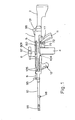
- the gas operated automatic gun shown in Figure 1 has a receiver 1 to the rear wall channel 131 of which is connected a buttstock 2 and at the opposite end of the receiver 1 from the buttstock 2 there is connected a barrel 10.
- a pistol grip 11 is connected by a screw and nut underneath the receiver 1 and a fore grip 12 is connected by screws on the underside of the barrel 10.
- the pistol grip 11 is connected to the receiver 1 through the intermediary of a trigger guard 72 shrouding a trigger assembly 73 having a rotatable sear actuator (safety catch) 77.
- a cartridge magazine 4 which is of the drum type although it may be a flat box- type magazine.
- the magazine 4 is held to the receiver by a magazine latch assembly 5.
- a cocking handle assembly 6 is mounted on the left hand side of the receiver 1 incorporating a cocking bar sub-assembly 60 including a cocking handle 601.
- a rear sight mount 96 mounted on the top rear of the receiver 1 and on the right hand side of the receiver is a carrying handle 97. Also on the right hand side of the receiver is an ejector slot 104 and in both sides at the front of the receiver are provided four cooling apertures 105 to assist in removing heat from the rear end of the barrel 10.
- a gas system 9 is connected in between the front of the receiver 1 and a foresight assembly 95.
- a bayonet lug attachment 98 is provided on the barrel and at the muzzle there is a flash suppressor 99.
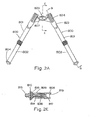
- the bipod shown in Figures 2A and 3 has a pair of telescoped tubular legs 800, each having an outer leg 801 and an inner leg 802.
- the top of the outer leg 801 is pivotally connected to a mounting assembly 803 and the lower end of each of the inner legs is connected to a foot 804 by a split pin 805.
- the mounting assembly 803 is formed by a yoke-shaped sub-frame 806 having upwardly extending wings, an elongate slotted mouth 807 and a forwardly extending tube 808 which has an axially extending slot 809 in the outer periphery thereof.
- a generally U-shaped bracket 810 Connected to the sub-frame 806 and forming the other part of the mounting assembly 803 is a generally U-shaped bracket 810 having side limbs which have a major downwardly sloping surface that provides the bipod with its apex angle.
- Each side limb 811 is connected to a respective wing of the yoke-shaped sub-frame 806 by welding and the lower rearwardly facing portion of each side limbs 811 is arcuately contoured.
- each limb is provided with a rearwardly facing slot 812 and a downwardly extending slot 813, the slots 812 and 813 being provided for predeterminedly securing the legs 800 in either a downward position for contacting the ground or in a raised position in which the legs extend rearwardly alongside the gun receiver.
- a plunger 814 mounted in the tube 808 and extending forwardly through the bracket 810 is a plunger 814 on which is machined, at its outer extremity, a part spherical ball 815 which forms one part of a ball joint.
- the plunger 814 is biassed by a compression spring 836 and captured within the tube 808 by a cross-pin 816.
- the spring 836 is retained within the tube 808 by an interior wall in which is disposed an axial hole 817 having a diameter sufficient to permit the plunger stem to pass therethrough to abut a circularly cross-sectioned gun mounting lug 818 (shown in Figure 5) which is inserted, in operation, into a port 819 of the tube 808.
- the purpose for the abutting relationship is to reduce the possibility of the bipod being accidentally detached from the g un.
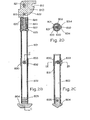
- a rod 820 inserted into the top of the outer leg 801 and shaped to fit inside the leg 801 is a rod 820 having its upper portion cut in an axial direction with a cruciform shape (not shown in detail).
- One part of the crucifonn, shown in Figure 2A and Figure 3, is for permitting traverse of the arcuate portion of the bracket 810 and the other part of the crucifonn is provided to permit the leg to be inserted over an axle 821.
- the axle 821 has a circular cross-section and two pairs of flat surfaces which are axially spaced with flat surfaces of each pair being diametrically opposed and the flat surfaces of the axle 821 cooperate with the said other part of the cruciform in the rod 820.
- a stop pin 822 Inserted into a hole in the rod 820 is a stop pin 822 which cooperates with the slots 812 and 813 of the bracket. Also suspended fromthe axle 821 is a hanger 823 having relieved upper portions 824 to enable hanger to rotate around the arcuate portion of the bracket 810 and relieved lower portions to provide clearance between the hanger and the gun receiver when the legs are raised. Inserted through the combination of hanger 823 and rod 820 is a take-down pin 825 having a central reduced portion to accommodate a compression spring which is located thereby and biassed therebetween and the top of an axial closed bore in the rod 820.
- a slot 827 passing diametrically through the rod 820 permits the leg to be axially movable so that the stop pin 822 may be removed from the slot 813 and the leg rotated around the arcuate surface of the bracket to the slot 812 with the bias of the spring 826 effectively pushing on the hanger 823 through the pin 825 causing the stop pin 822 to be pushed away from the take-down pin 825 and, therefore, into the slots 812 or 813.
- each of the lower inner legs 802 is formed a series of axially extending holes 828 linked together by slots 829 to form a continuous slot with a series of local expansions, as shown in figures 3, 5 and 6.
- Circumferentially surrounding the lower end of the outer leg is a collar 830.
- a pin 831 which is spring biassed against a latch button 832 by a compression spring 833, the spring being secured over a portion of the pin 831 and inside a bore of the latch button 832.
- the latch button 832 is circular in cross-section but has two diametrically opposed flat surfaces 834 which protrude through an aperture in the collar and in this manner, by virtue of the spring 833 and pin 831, the button is biassed outwardly against the interior wall of the collar 830.
- the distance between the flat surfaces 834 of the button is arranged so that the button is able to slide in the slot 829 of the inner leg and the full diameter of the button 832 is such that it is able to engage the local hole expansions 828, and by virtue of the force of the spring 833 so the button is pushed outwardly to lock the inner leg to one of the expanded hole portions in the outer leg.
- the collar has the added function of circumferentially surrounding the outer leg and since the outer leg is weakened by the provision of the linked holes so the collar provides a support for the lower portion of tile outer leg to prevent the outer leg from splitting.
- the bipod is shown partially mounted onto the lug 818 and to enable the mouth of the binod to be inserted over the lug 818, the lug is undercut at its lower root portion and chamfered at its top outer portion.
- the lug 818 When secured to the gun the lug 818 is situated in the mouth 807 and the ball 815 is sprung loaded into a socket 835 axially arranged in front of the lug 818.
- the socket 835 is simply a hole drilled through a plate member and to release the bipod from the gun, the ball 815 is depressed from a forwards direction of the gun against the force of the spring 816.
- the button 832 is depressed and the collar 830 pulled away from the bracket 810 until the desired extension is reached when the button is released to engage with one of the holes 828.
- the ability of the present bipod to permit a gun to roll in the Y plane is demonstrated, and the gun (shown in phantom lines) rolls about the ball 815 and lug 818.
- the present invention also permits the gun to sweep in the X plane and this is shown in Figure 5 where the gun (shown in phantom lines) is shown at one particular angle of sweep, the maximum angle being determined by the width of the mouth 807.
Landscapes
- Engineering & Computer Science (AREA)
- General Engineering & Computer Science (AREA)
- Toys (AREA)
Priority Applications (1)
| Application Number | Priority Date | Filing Date | Title |
|---|---|---|---|
| EP84106491A EP0127193A1 (fr) | 1980-12-11 | 1980-12-11 | Bipied pour arme à feu et arme à feu comportant un tel bipied |
Applications Claiming Priority (1)
| Application Number | Priority Date | Filing Date | Title |
|---|---|---|---|
| EP84106491A EP0127193A1 (fr) | 1980-12-11 | 1980-12-11 | Bipied pour arme à feu et arme à feu comportant un tel bipied |
Related Parent Applications (1)
| Application Number | Title | Priority Date | Filing Date |
|---|---|---|---|
| EP80304481.7 Division | 1980-12-11 |
Publications (1)
| Publication Number | Publication Date |
|---|---|
| EP0127193A1 true EP0127193A1 (fr) | 1984-12-05 |
Family
ID=8191971
Family Applications (1)
| Application Number | Title | Priority Date | Filing Date |
|---|---|---|---|
| EP84106491A Withdrawn EP0127193A1 (fr) | 1980-12-11 | 1980-12-11 | Bipied pour arme à feu et arme à feu comportant un tel bipied |
Country Status (1)
| Country | Link |
|---|---|
| EP (1) | EP0127193A1 (fr) |
Cited By (9)
| Publication number | Priority date | Publication date | Assignee | Title |
|---|---|---|---|---|
| AT1744U1 (de) * | 1996-09-10 | 1997-10-27 | Steyr Daimler Puch Ag | Gewehr mit zweibein |
| US6763627B1 (en) * | 2003-07-16 | 2004-07-20 | Fn Mfg Inc | Bipod for light-weight machine gun |
| DE202006001450U1 (de) * | 2006-01-31 | 2007-06-06 | Heckler & Koch Gmbh | Zweibein für eine Waffe |
| US7426800B2 (en) * | 2004-12-22 | 2008-09-23 | Pierce Rodney W | Stabilization device |
| US7743545B1 (en) * | 2003-12-02 | 2010-06-29 | Grip Pod Systems, Llc | Vertical foregrip leg extender |
| US10113692B2 (en) | 2003-12-02 | 2018-10-30 | Grip Pod Systems International, Llc | Vertical fore grip with bipod |
| CN109489490A (zh) * | 2018-12-20 | 2019-03-19 | 西安现代控制技术研究所 | 适用于智能地雷武器系统野外布设的抗风型支腿机构 |
| WO2019134020A1 (fr) * | 2018-01-08 | 2019-07-11 | McEwin Design Pty Ltd | Bipied de fusil |
| US20230243614A1 (en) * | 2022-01-31 | 2023-08-03 | Sig Sauer, Inc. | Rifle bipod assembly |
Citations (7)
| Publication number | Priority date | Publication date | Assignee | Title |
|---|---|---|---|---|
| DE197104C (fr) * | ||||
| GB172213A (en) * | 1920-11-25 | 1921-12-08 | E R Watts & Son Ltd | Improvements in or relating to adjusting devices for scientific instruments |
| FR31385E (fr) * | 1926-06-04 | 1927-01-28 | Perfectionnements aux armes à feu automatiques | |
| US1618966A (en) * | 1922-10-31 | 1927-02-22 | William R Bull | Bipod |
| FR1273278A (fr) * | 1960-11-10 | 1961-10-06 | Viseur à double dérive | |
| GB1122836A (en) * | 1966-09-08 | 1968-08-07 | Rheinmetall Gmbh | Mounting for light automatic weapons |
| DE1578405A1 (de) * | 1966-01-21 | 1971-01-21 | Rheinmetall Gmbh | Zweibein fuer Gewehre |
-
1980
- 1980-12-11 EP EP84106491A patent/EP0127193A1/fr not_active Withdrawn
Patent Citations (7)
| Publication number | Priority date | Publication date | Assignee | Title |
|---|---|---|---|---|
| DE197104C (fr) * | ||||
| GB172213A (en) * | 1920-11-25 | 1921-12-08 | E R Watts & Son Ltd | Improvements in or relating to adjusting devices for scientific instruments |
| US1618966A (en) * | 1922-10-31 | 1927-02-22 | William R Bull | Bipod |
| FR31385E (fr) * | 1926-06-04 | 1927-01-28 | Perfectionnements aux armes à feu automatiques | |
| FR1273278A (fr) * | 1960-11-10 | 1961-10-06 | Viseur à double dérive | |
| DE1578405A1 (de) * | 1966-01-21 | 1971-01-21 | Rheinmetall Gmbh | Zweibein fuer Gewehre |
| GB1122836A (en) * | 1966-09-08 | 1968-08-07 | Rheinmetall Gmbh | Mounting for light automatic weapons |
Cited By (17)
| Publication number | Priority date | Publication date | Assignee | Title |
|---|---|---|---|---|
| AT1744U1 (de) * | 1996-09-10 | 1997-10-27 | Steyr Daimler Puch Ag | Gewehr mit zweibein |
| EP0836067A3 (fr) * | 1996-09-10 | 1999-03-17 | Steyr-Daimler-Puch Aktiengesellschaft | Fusil muni d'un support du type bipied |
| US6763627B1 (en) * | 2003-07-16 | 2004-07-20 | Fn Mfg Inc | Bipod for light-weight machine gun |
| US10502365B2 (en) | 2003-12-02 | 2019-12-10 | Grip Pod Systems International, Llc | Vertical fore grip with bipod |
| US7743545B1 (en) * | 2003-12-02 | 2010-06-29 | Grip Pod Systems, Llc | Vertical foregrip leg extender |
| US7861452B2 (en) | 2003-12-02 | 2011-01-04 | Grip Pods Systems, LLC | Vertical foregrip leg extender |
| US7987625B1 (en) | 2003-12-02 | 2011-08-02 | Grip Pod Systems, Llc | Vertical foregrip leg extender |
| US10113692B2 (en) | 2003-12-02 | 2018-10-30 | Grip Pod Systems International, Llc | Vertical fore grip with bipod |
| US7426800B2 (en) * | 2004-12-22 | 2008-09-23 | Pierce Rodney W | Stabilization device |
| DE202006001450U1 (de) * | 2006-01-31 | 2007-06-06 | Heckler & Koch Gmbh | Zweibein für eine Waffe |
| WO2007088002A1 (fr) | 2006-01-31 | 2007-08-09 | Heckler & Koch Gmbh | Bipode pour arme |
| US11391533B2 (en) | 2018-01-08 | 2022-07-19 | McEwin Design Pty Ltd | Rifle bipod |
| WO2019134020A1 (fr) * | 2018-01-08 | 2019-07-11 | McEwin Design Pty Ltd | Bipied de fusil |
| CN109489490A (zh) * | 2018-12-20 | 2019-03-19 | 西安现代控制技术研究所 | 适用于智能地雷武器系统野外布设的抗风型支腿机构 |
| CN109489490B (zh) * | 2018-12-20 | 2024-02-02 | 西安现代控制技术研究所 | 适用于智能地雷武器系统野外布设的抗风型支腿机构 |
| US20230243614A1 (en) * | 2022-01-31 | 2023-08-03 | Sig Sauer, Inc. | Rifle bipod assembly |
| US12560397B2 (en) * | 2022-01-31 | 2026-02-24 | Sig Sauer, Inc. | Rifle bipod assembly |
Similar Documents
| Publication | Publication Date | Title |
|---|---|---|
| GB2090951A (en) | Bipod for a gun | |
| US12140390B1 (en) | Firearm thumb rest | |
| US5090147A (en) | Self-engaging safety | |
| US4505182A (en) | Firearm trigger mechanism | |
| US4475437A (en) | Sear actuator | |
| US5325617A (en) | System for changing the barrel of a gun or weapon | |
| US4502367A (en) | Firearms bolt carrier assembly | |
| US3507067A (en) | Grenade launcher having a rotatable forwardly sliding barrel and removable firing mechanism | |
| US2970398A (en) | Mechanism to enable firing of shotgun with one arm | |
| CA2495379C (fr) | Systeme de recul destine a la boite de culasse d'une arme a feu | |
| US6553706B1 (en) | Sear and step trigger assembly having a secondary sear block | |
| US5018292A (en) | Linkage assembly for trigger/sear assemblies | |
| US9513074B1 (en) | Firearm with interchangeable parts | |
| US7340857B1 (en) | Recoil system for the forend of a firearm | |
| US5924231A (en) | Two stage match trigger assembly | |
| US5187312A (en) | Two stage trigger assembly | |
| US20190154382A1 (en) | Slide action rifle with a bolt carrier locking mechanism external to the receiver | |
| GB2305716A (en) | Improvements in or relating to firearms | |
| US11959714B2 (en) | Bolt assembly | |
| US7685755B1 (en) | Recoil system | |
| US4020577A (en) | Bolt handle adaptor for a bolt action rifle | |
| DE2442107A1 (de) | Halbautomatische feuerwaffe | |
| US9541342B1 (en) | Trigger travel adjustment insert | |
| US7770318B2 (en) | Recoil system for the forend of a firearm | |
| US4156980A (en) | Breech opening apparatus for handgun |
Legal Events
| Date | Code | Title | Description |
|---|---|---|---|
| PUAI | Public reference made under article 153(3) epc to a published international application that has entered the european phase |
Free format text: ORIGINAL CODE: 0009012 |
|
| AC | Divisional application: reference to earlier application |
Ref document number: 55307 Country of ref document: EP |
|
| AK | Designated contracting states |
Designated state(s): AT BE CH DE FR IT LI LU NL SE |
|
| STAA | Information on the status of an ep patent application or granted ep patent |
Free format text: STATUS: THE APPLICATION IS DEEMED TO BE WITHDRAWN |
|
| 18D | Application deemed to be withdrawn |
Effective date: 19850806 |
|
| RIN1 | Information on inventor provided before grant (corrected) |
Inventor name: SULLIVAN, LEROY JAMES |