EP0127314A2 - Fahrzeug-Scheibenbremse - Google Patents
Fahrzeug-Scheibenbremse Download PDFInfo
- Publication number
- EP0127314A2 EP0127314A2 EP84302775A EP84302775A EP0127314A2 EP 0127314 A2 EP0127314 A2 EP 0127314A2 EP 84302775 A EP84302775 A EP 84302775A EP 84302775 A EP84302775 A EP 84302775A EP 0127314 A2 EP0127314 A2 EP 0127314A2
- Authority
- EP
- European Patent Office
- Prior art keywords
- brake
- piston
- sleeve nut
- clutch
- shaft
- Prior art date
- Legal status (The legal status is an assumption and is not a legal conclusion. Google has not performed a legal analysis and makes no representation as to the accuracy of the status listed.)
- Withdrawn
Links
- 239000012530 fluid Substances 0.000 claims description 8
- 230000000712 assembly Effects 0.000 claims description 5
- 238000000429 assembly Methods 0.000 claims description 5
- 230000000694 effects Effects 0.000 claims 2
- 239000002783 friction material Substances 0.000 description 7
- 230000000717 retained effect Effects 0.000 description 2
- 239000000356 contaminant Substances 0.000 description 1
- 239000000428 dust Substances 0.000 description 1
Images

Classifications
-
- F—MECHANICAL ENGINEERING; LIGHTING; HEATING; WEAPONS; BLASTING
- F16—ENGINEERING ELEMENTS AND UNITS; GENERAL MEASURES FOR PRODUCING AND MAINTAINING EFFECTIVE FUNCTIONING OF MACHINES OR INSTALLATIONS; THERMAL INSULATION IN GENERAL
- F16D—COUPLINGS FOR TRANSMITTING ROTATION; CLUTCHES; BRAKES
- F16D65/00—Parts or details
- F16D65/38—Slack adjusters
- F16D65/40—Slack adjusters mechanical
- F16D65/52—Slack adjusters mechanical self-acting in one direction for adjusting excessive play
- F16D65/56—Slack adjusters mechanical self-acting in one direction for adjusting excessive play with screw-thread and nut
- F16D65/567—Slack adjusters mechanical self-acting in one direction for adjusting excessive play with screw-thread and nut for mounting on a disc brake
-
- F—MECHANICAL ENGINEERING; LIGHTING; HEATING; WEAPONS; BLASTING
- F16—ENGINEERING ELEMENTS AND UNITS; GENERAL MEASURES FOR PRODUCING AND MAINTAINING EFFECTIVE FUNCTIONING OF MACHINES OR INSTALLATIONS; THERMAL INSULATION IN GENERAL
- F16D—COUPLINGS FOR TRANSMITTING ROTATION; CLUTCHES; BRAKES
- F16D65/00—Parts or details
- F16D65/14—Actuating mechanisms for brakes; Means for initiating operation at a predetermined position
- F16D65/16—Actuating mechanisms for brakes; Means for initiating operation at a predetermined position arranged in or on the brake
- F16D65/18—Actuating mechanisms for brakes; Means for initiating operation at a predetermined position arranged in or on the brake adapted for drawing members together, e.g. for disc brakes
-
- F—MECHANICAL ENGINEERING; LIGHTING; HEATING; WEAPONS; BLASTING
- F16—ENGINEERING ELEMENTS AND UNITS; GENERAL MEASURES FOR PRODUCING AND MAINTAINING EFFECTIVE FUNCTIONING OF MACHINES OR INSTALLATIONS; THERMAL INSULATION IN GENERAL
- F16D—COUPLINGS FOR TRANSMITTING ROTATION; CLUTCHES; BRAKES
- F16D2121/00—Type of actuator operation force
- F16D2121/02—Fluid pressure
-
- F—MECHANICAL ENGINEERING; LIGHTING; HEATING; WEAPONS; BLASTING
- F16—ENGINEERING ELEMENTS AND UNITS; GENERAL MEASURES FOR PRODUCING AND MAINTAINING EFFECTIVE FUNCTIONING OF MACHINES OR INSTALLATIONS; THERMAL INSULATION IN GENERAL
- F16D—COUPLINGS FOR TRANSMITTING ROTATION; CLUTCHES; BRAKES
- F16D2121/00—Type of actuator operation force
- F16D2121/14—Mechanical
-
- F—MECHANICAL ENGINEERING; LIGHTING; HEATING; WEAPONS; BLASTING
- F16—ENGINEERING ELEMENTS AND UNITS; GENERAL MEASURES FOR PRODUCING AND MAINTAINING EFFECTIVE FUNCTIONING OF MACHINES OR INSTALLATIONS; THERMAL INSULATION IN GENERAL
- F16D—COUPLINGS FOR TRANSMITTING ROTATION; CLUTCHES; BRAKES
- F16D2123/00—Multiple operation forces
-
- F—MECHANICAL ENGINEERING; LIGHTING; HEATING; WEAPONS; BLASTING
- F16—ENGINEERING ELEMENTS AND UNITS; GENERAL MEASURES FOR PRODUCING AND MAINTAINING EFFECTIVE FUNCTIONING OF MACHINES OR INSTALLATIONS; THERMAL INSULATION IN GENERAL
- F16D—COUPLINGS FOR TRANSMITTING ROTATION; CLUTCHES; BRAKES
- F16D2125/00—Components of actuators
- F16D2125/18—Mechanical mechanisms
- F16D2125/20—Mechanical mechanisms converting rotation to linear movement or vice versa
- F16D2125/34—Mechanical mechanisms converting rotation to linear movement or vice versa acting in the direction of the axis of rotation
- F16D2125/40—Screw-and-nut
Definitions
- This invention relates to a vehicle disc brake assembly as specified in the preamble of claim 1, for example as disclosed in US-A-3,770,082.
- the present invention is concerned with a simplified arrangement in which a cylindrical sleeve nut is acted on by a clutch mechanism to actuate and deactuate the clutch for actuation and deactuation of a mechanically acting parking brake, as well as to adjust the brake as the brake is actuated.
- a vehicle disc brake assembly in accordance with the present invention is characterised by the features specified in the characterising portion of claim 1.
- a preferred embodiment of a vehicle disc brake assembly in accordance with the present invention uses a clutch mechanism acting on a sleeve nut, which is threaded on a shaft secured to or forming a part of the actuating piston.
- a mechanically rotated shaft and drive member assembly is connected to actuate and deactuate the clutch to transmit the parking brake force through the clutch to the sleeve nut and cause the threaded shaft to move the piston in the brake-engaging direction. Rotation of the shaft and drive member assembly in the other direction releases the clutch and permits retraction of the piston and threaded shaft.
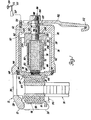
- a vehicle brake assembly 10 includes a caliper assembly 12 and a rotatable disc 14 operatively secured to a vehicle wheel (not shown).
- the disc 14 has opposed friction-braking surfaces 16 and 18.
- the caliper assembly is mounted on a mounting bracket (not shown) so that it is slidably movable during brake engagement and release.
- the vehicle brake system is schematically illustrated as also including a master cylinder 20 actuable by a brake pedal 22 pivotally mounted on a vehicle portion 24.
- the master cylinder is connected to the caliper assembly by a conduit 26.
- the caliper assembly 12 includes a caliper body 28 formed to provide an outboard caliper leg 30, an inboard caliper leg 32 and a bridge section 34 joining the two caliper legs and extending over the outer of the two caliper legs and also extending over the outer periphery of the disc 14.
- the inboard caliper leg 32 is formed to define a cylinder 36 having a cylinder side wall 38 and a cylinder end wall 40. The open end of the cylinder opens towards the outboard caliper leg 30.
- a cup-shaped piston 42 is slidably mounted in the cylinder 36 with the piston head 44 extending through the open end of the cylinder towards the friction-braking surface 18 of the disc 14.
- a seal 46 and a boot 48 are provided to seal the piston and cylinder and to prevent the entry of dust or other contaminants into the cylinder.
- the piston and the cylinder walls define a pressure chamber 50 to which the conduit 26 is connected by a pressure inlet 52.
- hydraulic fluid under pressure from the master cylinder 20 is introduced into the chamber 50 to actuate the brake.
- an air pressure arrangement would be provided to introduce air into the chamber 50 for that purpose.
- An outboard brake shoe assembly 54 comprising a backing plate 56 and friction material formed to provide a friction pad 58, is mounted on the outboard caliper leg 30 so that the friction material may engage the disc friction-braking surface 16 in friction-braking relation when the brake is actuated.
- An inboard brake shoe assembly 60 comprising a backing plate 62 and friction material forming a friction pad 64, is mounted to be engaged by the piston head 44 for movement with the piston 42 so that the friction material 64 engages the disc friction-braking surface 18 when the brake is actuated and retracts with the piston when the brake is released.
- the brake shoe assembly 60 engages the piston head 44 so as to prevent rotation of the piston in the cylinder 36, in a manner well known in the art.
- a threaded shaft 66 is secured to the piston head 44 at one end 68 of the shaft 66 so that the shaft extends axially within the piston and is located in the portion of the pressure chamber 50 contained within the piston 42.
- the shaft 66 has external threads 70 formed thereon, and a sleeve nut 72 having a threaded inner surface 74 is threaded on to the shaft 66.
- the sleeve nut outer surface 76 has at least a portion which defines a clutch inner surface.
- the outer surface 76 has an axially extending groove 78 therein.
- a coil spring clutch 80 is received about the sleeve nut outer surface 76 so that, in the normal relaxed condition of the clutch, the clutch does not grip the outer surface 76 of the sleeve nut.
- the clutch 80 has one end 82 extending inwardly and received in slidable relation in the sleeve nut groove 78. The other clutch end 84 extends outwardly.
- a shaft and drive member assembly 86 includes a shaft 88 that is rotatably mounted in an axially extending opening 90 formed through the cylinder end wall 40.
- the outer end of the shaft 88 is configured to receive an arm 92 thereon retained by a suitable device such as a retainer nut 94.
- the arm 92 is non-rotatably mounted on the shaft 88.
- a seal 96 in a shaft groove 98 seals the opening 90 against brake fluid leakage.
- the inner end 100 of the shaft 88 extends into the pressure chamber 50 and has a drive member 102 secured thereto.
- the drive member 102 is illustrated as being generally cup-shaped with a skirt section 104 extending over the spring clutch end 84.
- An internal groove 106 formed in the skirt section 104 receives the spring clutch end 84 therein in sliding relation. Rotation of the drive member 102 in either arcuate direction will move the spring clutch end 84 with it.
- Bearing elements in the form of washers 108 and 110 are mounted on the shaft 88 to provide bearing surfaces for the drive member 102 and arm 92.
- the master cylinder 20 is actuated, and brake fluid under pressure is delivered to the chamber 50.
- the pressure fluid acts against the piston 42 to move the piston and brake shoe assembly 60 towards the disc 14 until the friction material 64 engages the friction-braking surface 18 of the disc.
- the pressurization of the chamber 50 also causes the caliper housing 28 to move in the opposite direction to cause the friction material 58 of the outboard brake shoe assembly 54 to engage the other friction-braking surface 16 of the disc. Further pressurization generates braking action in well-known manner.
- Actuating movement of the piston 42 carries the threaded shaft 66 and sleeve nut 72 with the piston, the end 82 of the spring clutch co-operating with the groove 78 to permit sliding movement of the sleeve nut 72 relative to the clutch.
- the pressure in the chamber 50 is released and the piston retracts, actuated by the seal 46 in well-known manner. If the friction pads 58 and 64 have become sufficiently worn, the piston, as well as the threaded shaft 66 and sleeve nut 72, will return to an adjusted position.
- the arm 92 When it is desired to mechanically actuate the brake assembly, the arm 92 is rotated by suitable means such as a parking brake cable 112, thereby rotating the shaft 88 and drive member 102 in an arcuate direction.
- the drive member 102 carries the end 84 of the spring clutch with it, so exerting torsional stress on the spring clutch tending to wind it up, and thereby causing it to decrease its inner diameter until the spring coils engage the outer surface 76 of the sleeve nut 72 in gripping relation. Further rotation of the drive member 102 transmits brake-actuating forces through the spring clutch to drive the sleeve nut 72 arcuately.
- a sleeve nut 172 has a threaded inner surface 174 and is threaded on to a shaft 66.
- the sleeve nut outer surface 176 has a portion which defines a clutch inner race 178.
- a sprag clutch 180 is received about the clutch inner race 178 so that, in the normal relaxed condition of the clutch, the clutch does not grip the sleeve nut.
- the clutch 180 has rollers (sprags) 182 mounted in a cage 184 forming the clutch outer race 186. The sprags 182 are received in axially slidable relation on the sleeve nut race 178.
- a shaft and drive member assembly 187 includes a shaft 188 rotatably mounted in an axially extending opening 190 formed through a cylinder end wall 40.
- the outer end of the shaft 188 is configured to receive an arm 192 thereon, retained by a suitable device such as a retainer nut 194.
- the arm 192 is non-rotatably mounted on the shaft 188.
- a seal 196 in a shaft groove 198 seals the opening 190 against brake fluid leakage.
- the inner end 200 of the shaft -188 extends into a pressure chamber 50 and has a drive member 202 secured thereto.
- the drive member 202 is illustrated as being generally cylindrical, with a section 204 having the clutch cage 184 securely fitted therein so as to be arcuately driven thereby.
- a retainer 206 is secured in the open end of the section 204 and limits axial movement of the clutch 180 and sleeve nut 172 relative to the drive member 202. Rotation of the drive member 202 in either arcuate direction will move the clutch cage 184 with it.
- a suitable bearing element such as a washer 208 is mounted on the shaft 188 to provide a bearing surface for the shaft end 200.
- the master cylinder 20 is actuated, and brake fluid under pressure is thereby delivered to the chamber 50.
- the pressure fluid acts against the piston 42 to move the piston and brake shoe assembly 60 towards the disc 14 until the friction material 64 engages the friction braking surface 18 of the disc.
- the pressurization of the chamber 50 also causes the caliper housing 28 to move in the opposite direction, to engage the friction pad 58 of the outboard brake shoe assembly 54 with the other friction braking surface 16 of the disc. Further pressurization generates braking action in well-known manner.
- Actuating movement of the piston 42 carries the threaded shaft 66 and sleeve nut 172 with the piston, the clutch sprags 182 permitting sliding movement of the sleeve nut 172 relative to the clutch.
- the pressure in the chamber 50 is released and the piston retracts, actuated by a seal 46 in well-known manner. If the friction pads 58 and 64 have become sufficiently worn, the piston 42, as well as the threaded shaft 66 and sleeve nut 172, will return to an adjusted position.
- the arm 192 When it is desired to mechanically actuate the brake assembly, the arm 192 is rotated by suitable means such as parking brake cable 212, thereby rotating the shaft 188 and drive member 202 in an arcuate'direction.
- the drive member 202 carries the clutch cage 184 with it,locking the sprags on the outer race 186 formed by the cage 184 and on the inner race 178 of the sleeve nut 172. Further rotation of the drive member 202 transmits torsional brake-actuating forces through the clutch 180 to drive the sleeve nut 172 arcuately. This causes the threaded shaft 66 to be moved axially in the sleeve nut 172 towards the disc 14, thus driving the piston 42 in the brake-actuating direction.
- the brake shoe assemblies are forced into engagement with the disc 14 in the same manner as before, thereby actuating the brake assembly.
Landscapes
- Engineering & Computer Science (AREA)
- General Engineering & Computer Science (AREA)
- Mechanical Engineering (AREA)
- Braking Arrangements (AREA)
Applications Claiming Priority (2)
| Application Number | Priority Date | Filing Date | Title |
|---|---|---|---|
| US498900 | 1983-05-27 | ||
| US06/498,900 US4487295A (en) | 1983-05-27 | 1983-05-27 | Disc brake caliper with integral parking brake |
Publications (2)
| Publication Number | Publication Date |
|---|---|
| EP0127314A2 true EP0127314A2 (de) | 1984-12-05 |
| EP0127314A3 EP0127314A3 (de) | 1985-05-02 |
Family
ID=23982969
Family Applications (1)
| Application Number | Title | Priority Date | Filing Date |
|---|---|---|---|
| EP84302775A Withdrawn EP0127314A3 (de) | 1983-05-27 | 1984-04-25 | Fahrzeug-Scheibenbremse |
Country Status (2)
| Country | Link |
|---|---|
| US (1) | US4487295A (de) |
| EP (1) | EP0127314A3 (de) |
Cited By (7)
| Publication number | Priority date | Publication date | Assignee | Title |
|---|---|---|---|---|
| FR2600387A1 (fr) * | 1986-06-23 | 1987-12-24 | Wabco Westinghouse | Systeme de frein d'immobilisation pour vehicule et etrier de frein pour un tel systeme |
| EP0314282A1 (de) * | 1987-10-10 | 1989-05-03 | General Motors France | Scheibenbremssattel |
| WO1989010495A3 (en) * | 1988-04-19 | 1990-01-25 | Allied Signal Inc | Electrically operated disc brakes |
| EP0439205A1 (de) * | 1990-01-23 | 1991-07-31 | General Motors France | Scheibenbremse |
| EP0439204A1 (de) * | 1990-01-23 | 1991-07-31 | General Motors France | Scheibenbremse |
| WO2011104015A1 (de) * | 2010-02-23 | 2011-09-01 | Lucas Automotive Gmbh | Fahrzeugbremse mit spindel/mutter-anordnung |
| KR20160094969A (ko) * | 2013-12-06 | 2016-08-10 | 섀플러 테크놀로지스 아게 운트 코. 카게 | 마찰 클러치용 결합/분리 시스템 |
Families Citing this family (14)
| Publication number | Priority date | Publication date | Assignee | Title |
|---|---|---|---|---|
| DE3431773A1 (de) * | 1984-08-29 | 1986-03-13 | Deutsche Perrot-Bremse Gmbh, 6800 Mannheim | Mechanisch betaetigte gleitsattelscheibenbremse |
| US4565265A (en) * | 1985-01-25 | 1986-01-21 | General Motors Corporation | Hydraulic parking brake |
| JPH0346264Y2 (de) * | 1985-03-28 | 1991-09-30 | ||
| US4793447A (en) * | 1986-12-23 | 1988-12-27 | Allied-Signal Inc. | Electrically operated disc brake |
| US5148894A (en) * | 1990-10-11 | 1992-09-22 | Allied-Signal Inc. | Disk brake/parking brake with threaded piston rod and motor |
| US5201387A (en) * | 1991-05-22 | 1993-04-13 | Allied-Signal Inc. | Disc brake with variable width caliper and powered actuation |
| US5348123A (en) * | 1991-09-02 | 1994-09-20 | Akebono Brake Industry Co., Ltd. | Brake actuating apparatus for a vehicle |
| US5161648A (en) * | 1991-11-07 | 1992-11-10 | Allied-Signal Inc. | Disc brake with variable width caliper |
| US6311808B1 (en) * | 1996-02-09 | 2001-11-06 | Continental Teves Ag & Co., Ohg | Combined service and parking brake system |
| JP4399754B2 (ja) * | 2000-05-31 | 2010-01-20 | 日立オートモティブシステムズ株式会社 | 電動ディスクブレーキ |
| KR100560603B1 (ko) | 2004-03-29 | 2006-03-17 | 조한용 | 전동 모타를 이용한 브레이크 구동장치 |
| EP3260721B8 (de) * | 2016-06-21 | 2021-06-02 | ZF CV Systems Europe BV | Einstellungseinheit für eine fahrzeugscheibenbremse und scheibenbremse damit |
| US10436269B2 (en) * | 2017-04-18 | 2019-10-08 | Mando Corporation | Active retraction mechanism for low drag caliper brake |
| TWI680241B (zh) * | 2018-03-26 | 2019-12-21 | 黃奕誠 | 機械式碟剎結構改良 |
Family Cites Families (12)
| Publication number | Priority date | Publication date | Assignee | Title |
|---|---|---|---|---|
| US3378109A (en) * | 1966-08-29 | 1968-04-16 | Gen Motors Corp | Disc brake assembly |
| DE1600182C3 (de) * | 1967-05-20 | 1979-07-05 | Alfred Teves Gmbh, 6000 Frankfurt | Selbsttätig und stufenlos wirkende Nachstellvorrichtung für das Lüftspiel einer Teilbelag-Scheibenbremse |
| US3653470A (en) * | 1970-09-18 | 1972-04-04 | Gen Motors Corp | Disc brake with hydraulic and mechanical actuation and wear adjustment means |
| US3765513A (en) * | 1972-10-30 | 1973-10-16 | Gen Motors Corp | Brake actuating and adjusting mechanism |
| US3770082A (en) * | 1972-11-29 | 1973-11-06 | Gen Motors Corp | Disc brake caliper assembly |
| US4006802A (en) * | 1974-02-28 | 1977-02-08 | Kelsey-Hayes Company | Automatic adjustor for a brake mechanism |
| US3991859A (en) * | 1976-02-27 | 1976-11-16 | General Motors Corporation | Adjusting mechanism for a disc brake caliper assembly |
| JPS556075A (en) * | 1978-06-30 | 1980-01-17 | Akebono Brake Ind Co Ltd | Disk brake |
| FR2434310A1 (fr) * | 1978-08-24 | 1980-03-21 | Pont A Mousson | Mecanisme de commande de frein a disque |
| US4323143A (en) * | 1978-11-21 | 1982-04-06 | Akebono Brake Industry Co., Ltd. | Automatic gap adjusting device for disc brake incorporating mechanical brake mechanism |
| BR8000881A (pt) * | 1979-02-14 | 1980-10-21 | Kelsey Hayes Co | Ajustador de folga,mecanismo de freio e acionador de freio de calibre |
| DE2946854A1 (de) * | 1979-11-20 | 1981-06-11 | Alfred Teves Gmbh, 6000 Frankfurt | Mechanische bremsbetaetigungsvorrichtung fuer eine teilbelag-scheibenbremse |
-
1983
- 1983-05-27 US US06/498,900 patent/US4487295A/en not_active Expired - Fee Related
-
1984
- 1984-04-25 EP EP84302775A patent/EP0127314A3/de not_active Withdrawn
Cited By (12)
| Publication number | Priority date | Publication date | Assignee | Title |
|---|---|---|---|---|
| FR2600387A1 (fr) * | 1986-06-23 | 1987-12-24 | Wabco Westinghouse | Systeme de frein d'immobilisation pour vehicule et etrier de frein pour un tel systeme |
| EP0251848A3 (en) * | 1986-06-23 | 1988-10-12 | Wabco Westinghouse Equipements Ferroviaires | Parking brake for a vehicle, and brake caliper for such a device |
| US4921076A (en) * | 1986-06-23 | 1990-05-01 | Wabco Westinghouse Equipements Ferroviaries | Vehicle park braking system |
| EP0314282A1 (de) * | 1987-10-10 | 1989-05-03 | General Motors France | Scheibenbremssattel |
| WO1989010495A3 (en) * | 1988-04-19 | 1990-01-25 | Allied Signal Inc | Electrically operated disc brakes |
| EP0439205A1 (de) * | 1990-01-23 | 1991-07-31 | General Motors France | Scheibenbremse |
| EP0439204A1 (de) * | 1990-01-23 | 1991-07-31 | General Motors France | Scheibenbremse |
| WO2011104015A1 (de) * | 2010-02-23 | 2011-09-01 | Lucas Automotive Gmbh | Fahrzeugbremse mit spindel/mutter-anordnung |
| CN102770684A (zh) * | 2010-02-23 | 2012-11-07 | 卢卡斯汽车股份有限公司 | 具有丝杠/螺母机构的车辆制动器 |
| CN102770684B (zh) * | 2010-02-23 | 2015-03-11 | 卢卡斯汽车股份有限公司 | 具有丝杠/螺母机构的车辆制动器 |
| US9732812B2 (en) | 2010-02-23 | 2017-08-15 | Lucas Automotive Gmbh | Vehicle brake having spindle/nut arrangement |
| KR20160094969A (ko) * | 2013-12-06 | 2016-08-10 | 섀플러 테크놀로지스 아게 운트 코. 카게 | 마찰 클러치용 결합/분리 시스템 |
Also Published As
| Publication number | Publication date |
|---|---|
| EP0127314A3 (de) | 1985-05-02 |
| US4487295A (en) | 1984-12-11 |
Similar Documents
| Publication | Publication Date | Title |
|---|---|---|
| EP0127314A2 (de) | Fahrzeug-Scheibenbremse | |
| US3991859A (en) | Adjusting mechanism for a disc brake caliper assembly | |
| US6820730B2 (en) | Brake lining wear adjuster assembly | |
| US4374551A (en) | Mechanical actuating device for a spot-type disc brake | |
| CA1183465A (en) | Automatic slack adjuster | |
| US3835961A (en) | Disk type brake | |
| US4394890A (en) | Automatic slack adjuster | |
| US3848705A (en) | Application adjuster for disc brake | |
| US4014411A (en) | Mechanically actuated disc brake with self adjusting feature | |
| JPS5847578B2 (ja) | シヤリヨウブレ−キソウサヨウモ−タ−シリンダ− | |
| JPS5928783B2 (ja) | 車両用ブレ−キのアクチュエ−タ | |
| US4565265A (en) | Hydraulic parking brake | |
| EP0154398B1 (de) | Brems-Betätigungsvorrichtung | |
| US5613577A (en) | Automotive disc brake with improved caliper assembly | |
| GB2099524A (en) | Disc brake | |
| US3820635A (en) | Self adjusting disc brake with parking brake | |
| GB2130667A (en) | Improvements in disc brakes for vehicles | |
| RU2156386C1 (ru) | Дисковый тормоз с устройством для автоматической регулировки зазоров | |
| US3726367A (en) | Combined service and parking brake | |
| US4800993A (en) | Tandem parking brake caliper for disc brakes | |
| CA1274194A (en) | Brake actuator | |
| US5738189A (en) | Adjustment mechanism for disc brake, with improved over-torque clutch | |
| EP0314282A1 (de) | Scheibenbremssattel | |
| US4926980A (en) | Automatic brake adjusting mechanism | |
| US3670853A (en) | Disc brake with parking brake |
Legal Events
| Date | Code | Title | Description |
|---|---|---|---|
| PUAI | Public reference made under article 153(3) epc to a published international application that has entered the european phase |
Free format text: ORIGINAL CODE: 0009012 |
|
| AK | Designated contracting states |
Designated state(s): DE FR GB |
|
| PUAL | Search report despatched |
Free format text: ORIGINAL CODE: 0009013 |
|
| AK | Designated contracting states |
Designated state(s): DE FR GB |
|
| RHK1 | Main classification (correction) |
Ipc: F16D 65/56 |
|
| 17P | Request for examination filed |
Effective date: 19850528 |
|
| 17Q | First examination report despatched |
Effective date: 19860930 |
|
| STAA | Information on the status of an ep patent application or granted ep patent |
Free format text: STATUS: THE APPLICATION HAS BEEN WITHDRAWN |
|
| 18W | Application withdrawn |
Withdrawal date: 19870415 |
|
| RIN1 | Information on inventor provided before grant (corrected) |
Inventor name: MITCHELL, CLARENCE IVAN |