EP0127568B1 - Kühlungsvorrichtung für Elektrodennippelverbindung an Lichtbogenöfen - Google Patents
Kühlungsvorrichtung für Elektrodennippelverbindung an Lichtbogenöfen Download PDFInfo
- Publication number
- EP0127568B1 EP0127568B1 EP84730042A EP84730042A EP0127568B1 EP 0127568 B1 EP0127568 B1 EP 0127568B1 EP 84730042 A EP84730042 A EP 84730042A EP 84730042 A EP84730042 A EP 84730042A EP 0127568 B1 EP0127568 B1 EP 0127568B1
- Authority
- EP
- European Patent Office
- Prior art keywords
- nipple
- electrode
- wall
- section
- conical
- Prior art date
- Legal status (The legal status is an assumption and is not a legal conclusion. Google has not performed a legal analysis and makes no representation as to the accuracy of the status listed.)
- Expired
Links
- 238000001816 cooling Methods 0.000 title claims abstract description 17
- 210000002445 nipple Anatomy 0.000 claims abstract description 21
- OKTJSMMVPCPJKN-UHFFFAOYSA-N Carbon Chemical compound [C] OKTJSMMVPCPJKN-UHFFFAOYSA-N 0.000 claims description 5
- 229910002804 graphite Inorganic materials 0.000 claims description 5
- 239000010439 graphite Substances 0.000 claims description 5
- 238000010891 electric arc Methods 0.000 claims 1
- 239000012809 cooling fluid Substances 0.000 abstract 1
- 238000006073 displacement reaction Methods 0.000 abstract 1
- 210000000078 claw Anatomy 0.000 description 3
- 239000002131 composite material Substances 0.000 description 3
- XLYOFNOQVPJJNP-UHFFFAOYSA-N water Substances O XLYOFNOQVPJJNP-UHFFFAOYSA-N 0.000 description 3
- 239000000110 cooling liquid Substances 0.000 description 2
- 229910000831 Steel Inorganic materials 0.000 description 1
- 238000010276 construction Methods 0.000 description 1
- 238000010438 heat treatment Methods 0.000 description 1
- 239000000463 material Substances 0.000 description 1
- 239000002184 metal Substances 0.000 description 1
- 238000010079 rubber tapping Methods 0.000 description 1
- 239000010959 steel Substances 0.000 description 1
- 230000007704 transition Effects 0.000 description 1
Images
Classifications
-
- H—ELECTRICITY
- H05—ELECTRIC TECHNIQUES NOT OTHERWISE PROVIDED FOR
- H05B—ELECTRIC HEATING; ELECTRIC LIGHT SOURCES NOT OTHERWISE PROVIDED FOR; CIRCUIT ARRANGEMENTS FOR ELECTRIC LIGHT SOURCES, IN GENERAL
- H05B7/00—Heating by electric discharge
- H05B7/02—Details
- H05B7/12—Arrangements for cooling, sealing or protecting electrodes
-
- H—ELECTRICITY
- H05—ELECTRIC TECHNIQUES NOT OTHERWISE PROVIDED FOR
- H05B—ELECTRIC HEATING; ELECTRIC LIGHT SOURCES NOT OTHERWISE PROVIDED FOR; CIRCUIT ARRANGEMENTS FOR ELECTRIC LIGHT SOURCES, IN GENERAL
- H05B7/00—Heating by electric discharge
- H05B7/02—Details
- H05B7/10—Mountings, supports, terminals or arrangements for feeding or guiding electrodes
- H05B7/101—Mountings, supports or terminals at head of electrode, i.e. at the end remote from the arc
Definitions
- the invention relates to a cooling device for electrode connection nipples for arc furnaces according to the preamble of the claim.
- a composite electrode is known, the upper section - which is made of steel - is cooled.
- This permanent section is connected to the graphite electrode section by means of a nipple, the latter being designed as a double cone and screwed into both sections.
- the nipple is made of the same material as the lower electrode section, i.e. graphite.
- the cooling liquid is guided in the interior of the upper electrode section in such a way that the nipple is also sufficiently cooled.
- Cooling is of particular importance because box breakage often occurs, particularly in the area of the nippling, which damages the furnace operation very much.
- a graphite electrode is known from DE-A1-31 44 926, which can be positively engaged with an electrode holder of an electric furnace.
- very high temperatures occur in practice. This will damage the tie rod head, the connector and especially the tie rod.
- the non-contact arrangement of the electrode connection device inside the double-walled current-carrying tube is not sufficient to cool the device and the nipple.
- a cooling device of an electrode nipple connection according to the preamble of the patent claim is known from EP-A1-0 053 200.
- the object of the invention is to provide an effective cooling device for the electrode sections of a composite electrode which are connected to one another by tensile force, the electrical current flowing exclusively through the outer surfaces of the electrodes and not through the nipple. to find.
- the nipple and the connecting elements are intensively g, e-cooled by contact pressure over the entire conical contact surface of the cooling sleeve.
- the water connections of the sleeve do not have to be disconnected when tapping on and off.
- the electrode is double-walled, with the cooling chamber connected to the cooling circuit.
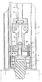
- the nipple 2 is positively connected to the electrode 1 and the metal transducer 3 via a thread, the upper part of the nipple 2 or the transducer 3 is conical in the example shown.
- the transducer 3 with the nipple 2 and the electrode 1 is firmly attracted to the end face K of the water-cooled electrode section 9.
- the transducer 3 slides with its conical outer surface into the conical opening of a cooling sleeve 5.
- the cooling sleeve 5 is guided over guide rods 8 in a guide ring 7 and pressed onto the transducer 3 via springs 6, so that between the contact surfaces of the Sensor 3 and the cooling sleeve 5 a good contact arises.
- the cooling sleeve 5 is water-cooled and connected to a water cooling circuit via the lines 11 and 13.
- a corrugated tube (compensator) 10 in the water pipes to compensate for the upward movement caused when the tube is pulled up.
- This corrugated tube can also be designed such that, in addition to the compensation, it also has the function of the axial movement of the sleeve 5 in the direction of the lower electrode section 1, corresponding to the springs 6.
- Flow guide plates 4 are arranged in the cooling sleeve 5 in order to intensify the cooling.
- the electrode section 9 is of double-walled design, the part receiving the cooling liquid being designated 21.
- the gripping claws 12 engage the pulling head 20 of the pickup 3. They are articulated to a claw head, to which the pull rod 14 is connected.
Landscapes
- Physics & Mathematics (AREA)
- Engineering & Computer Science (AREA)
- Plasma & Fusion (AREA)
- Discharge Heating (AREA)
- Furnace Details (AREA)
- Carbon And Carbon Compounds (AREA)
- Vertical, Hearth, Or Arc Furnaces (AREA)
Priority Applications (1)
| Application Number | Priority Date | Filing Date | Title |
|---|---|---|---|
| AT84730042T ATE41581T1 (de) | 1983-05-26 | 1984-04-16 | Kuehlungsvorrichtung fuer elektrodennippelverbindung an lichtbogenoefen. |
Applications Claiming Priority (2)
| Application Number | Priority Date | Filing Date | Title |
|---|---|---|---|
| DE3319389A DE3319389C2 (de) | 1983-05-26 | 1983-05-26 | Elektrode für Lichtbogenöfen |
| DE3319389 | 1983-05-26 |
Publications (2)
| Publication Number | Publication Date |
|---|---|
| EP0127568A1 EP0127568A1 (de) | 1984-12-05 |
| EP0127568B1 true EP0127568B1 (de) | 1989-03-15 |
Family
ID=6200103
Family Applications (1)
| Application Number | Title | Priority Date | Filing Date |
|---|---|---|---|
| EP84730042A Expired EP0127568B1 (de) | 1983-05-26 | 1984-04-16 | Kühlungsvorrichtung für Elektrodennippelverbindung an Lichtbogenöfen |
Country Status (7)
| Country | Link |
|---|---|
| US (1) | US4615036A (da) |
| EP (1) | EP0127568B1 (da) |
| JP (1) | JPS59226499A (da) |
| AT (1) | ATE41581T1 (da) |
| DE (1) | DE3319389C2 (da) |
| DK (1) | DK159037C (da) |
| ES (1) | ES532661A0 (da) |
Families Citing this family (1)
| Publication number | Priority date | Publication date | Assignee | Title |
|---|---|---|---|---|
| US4964114A (en) * | 1986-11-26 | 1990-10-16 | Mannesmann Ag | Electrode positioning mechanism |
Citations (2)
| Publication number | Priority date | Publication date | Assignee | Title |
|---|---|---|---|---|
| EP0053200A1 (de) * | 1980-12-02 | 1982-06-09 | Arc Technologies Systems, Ltd. | Elektrode für Lichtbogenschmelzöfen |
| EP0106767A1 (fr) * | 1982-10-15 | 1984-04-25 | Clecim | Dispositif de mesure de tension d'arc sur un four électrique |
Family Cites Families (10)
| Publication number | Priority date | Publication date | Assignee | Title |
|---|---|---|---|---|
| US824153A (en) * | 1904-05-03 | 1906-06-26 | Willson Aluminum Company | Carbon-holder for electric furnaces. |
| US4121042A (en) * | 1976-09-01 | 1978-10-17 | The Steel Company Of Canada Limited | Composite electrode with non-consumable upper section |
| US4168392A (en) * | 1976-09-01 | 1979-09-18 | The Steel Company Of Canada, Limited | Composite electrode with non-consumable upper section |
| US4287381A (en) * | 1978-12-19 | 1981-09-01 | British Steel Corporation | Electric arc furnace electrodes |
| GB2087699B (en) * | 1980-11-17 | 1984-07-18 | Leybold Heraeus Gmbh & Co Kg | Graphite electrode for use in an electric furnace |
| DE3144926C2 (de) * | 1980-11-17 | 1987-04-16 | Leybold-Heraeus GmbH, 5000 Köln | Grafitelektrode für den Einsatz in einen Elektrodenhalter eines Elektroofens |
| DE3102776A1 (de) * | 1981-01-28 | 1982-08-26 | C. Conradty Nürnberg GmbH & Co KG, 8505 Röthenbach | Elektrode fuer lichtbogenoefen |
| ATE14816T1 (de) * | 1981-03-24 | 1985-08-15 | Krupp Gmbh | Hochstromleitungssystem fuer elektrooefen. |
| CA1199358A (en) * | 1982-06-04 | 1986-01-14 | Robert W. Montgomery | Electric arc furnace electrodes |
| US4451926A (en) * | 1982-08-03 | 1984-05-29 | Great Lakes Carbon Corporation | Composite electrode for arc furnace |
-
1983
- 1983-05-26 DE DE3319389A patent/DE3319389C2/de not_active Expired
-
1984
- 1984-04-05 JP JP59068341A patent/JPS59226499A/ja active Granted
- 1984-04-16 EP EP84730042A patent/EP0127568B1/de not_active Expired
- 1984-04-16 AT AT84730042T patent/ATE41581T1/de active
- 1984-05-21 US US06/612,423 patent/US4615036A/en not_active Expired - Fee Related
- 1984-05-21 ES ES532661A patent/ES532661A0/es active Granted
- 1984-05-25 DK DK258184A patent/DK159037C/da not_active IP Right Cessation
Patent Citations (2)
| Publication number | Priority date | Publication date | Assignee | Title |
|---|---|---|---|---|
| EP0053200A1 (de) * | 1980-12-02 | 1982-06-09 | Arc Technologies Systems, Ltd. | Elektrode für Lichtbogenschmelzöfen |
| EP0106767A1 (fr) * | 1982-10-15 | 1984-04-25 | Clecim | Dispositif de mesure de tension d'arc sur un four électrique |
Also Published As
| Publication number | Publication date |
|---|---|
| JPH0372192B2 (da) | 1991-11-15 |
| DK159037B (da) | 1990-08-20 |
| US4615036A (en) | 1986-09-30 |
| DK258184D0 (da) | 1984-05-25 |
| ATE41581T1 (de) | 1989-04-15 |
| JPS59226499A (ja) | 1984-12-19 |
| DE3319389A1 (de) | 1984-11-29 |
| ES8502830A1 (es) | 1985-01-16 |
| DK159037C (da) | 1991-02-04 |
| DK258184A (da) | 1984-11-27 |
| ES532661A0 (es) | 1985-01-16 |
| DE3319389C2 (de) | 1987-03-05 |
| EP0127568A1 (de) | 1984-12-05 |
Similar Documents
| Publication | Publication Date | Title |
|---|---|---|
| DE68919567T2 (de) | Elektro-Schweissmuffe mit Anzeigemitteln des Schweissergebnisses. | |
| EP1756464B1 (de) | Verbindungsanordnung, insbesondere zum kraftschlüssigen anbinden von mindestens einem faserverbund-bauteil an ein weiteres bauteil | |
| DE69614429T2 (de) | Widerstandsschweiss-Sensor | |
| DE3414284A1 (de) | Elektrisches heizelement fuer rohrleitungen, insbesondere fuer lange rohrleitungen | |
| DE2314669C2 (de) | Zündkerze | |
| EP0127568A1 (de) | Kühlungsvorrichtung für Elektrodennippelverbindung an Lichtbogenöfen | |
| DE69918955T2 (de) | Brenner für automatisierte schweissvorrichtungen | |
| DE3420821C1 (de) | Wassergekühltes Hochstromkabel I | |
| DE102017121158B3 (de) | Druckmittler und Bauteilanordnung zum Schützen eines Druckmessumformers vor der Einwirkung eines unter einem zu messenden Druck stehenden Fluids sowie Verfahren zum Verschweißen eines Druckmessumformers mit einem Druckmittler | |
| EP0799802B1 (de) | Modularer Halter für eine gekühlte Glasschmelz-Tauchelektrode | |
| DE19508433C1 (de) | Modularer Halter für eine gekühlte Glasschmelz-Tauchelektrode | |
| DE19740912C1 (de) | Flexibles, mit Kühlmittel durchströmbares Kabelstück | |
| HUT53954A (en) | Joint for steel tubes | |
| DE10222559B4 (de) | Rohrkompensatoranordnung zur Aufnahme von bei Erwärmung oder Abkühlung eines Leitungsrohrs auftretenden axialen und lateralen Bewegungen | |
| EP0331947B1 (de) | Spannhülse für Elektroden in Brennern, insbesondere WIG-Brennern | |
| EP0381996B1 (de) | Ionenerzeugende Einrichtung | |
| DE8715620U1 (de) | Vorrichtung zum Kuppeln kühlmittelführender Stromrohre | |
| AT393310B (de) | Anschlussvorrichtung an einem behaelter | |
| DE4446015C2 (de) | Gasdüse für Schutzgaslichtbogenschweiß- und Schneidbrenner | |
| DE2612374C3 (de) | Einblickstutzen für die optische Kontrolle heißer Zonen im Inneren von Behältern | |
| EP0699484B1 (de) | Vorrichtung zum Schmelzen und dosiertem Abgeben von thermoplastischem Klebstoff | |
| AT323210B (de) | Halterung für gekrümmte rohre | |
| DE2415920C3 (de) | Verfahren zur Verbesserung der Kontaktierung bei einem Durchführungsleiter mit Eisenmantel und Kupferseele | |
| DE102016108844A1 (de) | Wärmekopfaufsatz, System und Verfahren zum Lösen einer Klebeverbindung zwischen Bauteilen | |
| DE2439717A1 (de) | Universal-verschraubung fuer loetanschluesse und klemmring-verschraubung mit unterschiedlichen rohrdurchmessern, insbesondere fuer verteiler-verschraubung fuer ein- und/oder zweirohrheizungen |
Legal Events
| Date | Code | Title | Description |
|---|---|---|---|
| PUAI | Public reference made under article 153(3) epc to a published international application that has entered the european phase |
Free format text: ORIGINAL CODE: 0009012 |
|
| AK | Designated contracting states |
Designated state(s): AT CH FR GB IT LI SE |
|
| 17P | Request for examination filed |
Effective date: 19840630 |
|
| 17Q | First examination report despatched |
Effective date: 19870518 |
|
| ITF | It: translation for a ep patent filed | ||
| GRAA | (expected) grant |
Free format text: ORIGINAL CODE: 0009210 |
|
| AK | Designated contracting states |
Kind code of ref document: B1 Designated state(s): AT CH FR GB IT LI SE |
|
| REF | Corresponds to: |
Ref document number: 41581 Country of ref document: AT Date of ref document: 19890415 Kind code of ref document: T |
|
| ET | Fr: translation filed | ||
| GBT | Gb: translation of ep patent filed (gb section 77(6)(a)/1977) | ||
| PLBE | No opposition filed within time limit |
Free format text: ORIGINAL CODE: 0009261 |
|
| STAA | Information on the status of an ep patent application or granted ep patent |
Free format text: STATUS: NO OPPOSITION FILED WITHIN TIME LIMIT |
|
| 26N | No opposition filed | ||
| PGFP | Annual fee paid to national office [announced via postgrant information from national office to epo] |
Ref country code: FR Payment date: 19920312 Year of fee payment: 9 |
|
| PGFP | Annual fee paid to national office [announced via postgrant information from national office to epo] |
Ref country code: GB Payment date: 19920316 Year of fee payment: 9 Ref country code: CH Payment date: 19920316 Year of fee payment: 9 |
|
| PGFP | Annual fee paid to national office [announced via postgrant information from national office to epo] |
Ref country code: SE Payment date: 19920323 Year of fee payment: 9 |
|
| PGFP | Annual fee paid to national office [announced via postgrant information from national office to epo] |
Ref country code: AT Payment date: 19920326 Year of fee payment: 9 |
|
| ITTA | It: last paid annual fee | ||
| PG25 | Lapsed in a contracting state [announced via postgrant information from national office to epo] |
Ref country code: GB Effective date: 19930416 Ref country code: AT Effective date: 19930416 |
|
| PG25 | Lapsed in a contracting state [announced via postgrant information from national office to epo] |
Ref country code: SE Effective date: 19930417 |
|
| PG25 | Lapsed in a contracting state [announced via postgrant information from national office to epo] |
Ref country code: LI Effective date: 19930430 Ref country code: CH Effective date: 19930430 |
|
| GBPC | Gb: european patent ceased through non-payment of renewal fee |
Effective date: 19930416 |
|
| PG25 | Lapsed in a contracting state [announced via postgrant information from national office to epo] |
Ref country code: FR Effective date: 19931229 |
|
| REG | Reference to a national code |
Ref country code: CH Ref legal event code: PL |
|
| REG | Reference to a national code |
Ref country code: FR Ref legal event code: ST |
|
| EUG | Se: european patent has lapsed |
Ref document number: 84730042.3 Effective date: 19931110 |