EP0127573A1 - Générateur d'aérosol - Google Patents
Générateur d'aérosol Download PDFInfo
- Publication number
- EP0127573A1 EP0127573A1 EP84810141A EP84810141A EP0127573A1 EP 0127573 A1 EP0127573 A1 EP 0127573A1 EP 84810141 A EP84810141 A EP 84810141A EP 84810141 A EP84810141 A EP 84810141A EP 0127573 A1 EP0127573 A1 EP 0127573A1
- Authority
- EP
- European Patent Office
- Prior art keywords
- lever
- spray dispenser
- trigger
- room spray
- dispenser according
- Prior art date
- Legal status (The legal status is an assumption and is not a legal conclusion. Google has not performed a legal analysis and makes no representation as to the accuracy of the status listed.)
- Granted
Links
Images


Classifications
-
- B—PERFORMING OPERATIONS; TRANSPORTING
- B65—CONVEYING; PACKING; STORING; HANDLING THIN OR FILAMENTARY MATERIAL
- B65D—CONTAINERS FOR STORAGE OR TRANSPORT OF ARTICLES OR MATERIALS, e.g. BAGS, BARRELS, BOTTLES, BOXES, CANS, CARTONS, CRATES, DRUMS, JARS, TANKS, HOPPERS, FORWARDING CONTAINERS; ACCESSORIES, CLOSURES, OR FITTINGS THEREFOR; PACKAGING ELEMENTS; PACKAGES
- B65D83/00—Containers or packages with special means for dispensing contents
- B65D83/14—Containers for dispensing liquid or semi-liquid contents by internal gaseous pressure, i.e. aerosol containers comprising propellant
- B65D83/16—Actuating means
- B65D83/26—Actuating means operating automatically, e.g. periodically
- B65D83/267—Actuating means operating automatically, e.g. periodically by a separate device actuated by repeated, e.g. human, input, e.g. by a moving wing of a door or window, a ringing doorbell, a flushing toilet
-
- B—PERFORMING OPERATIONS; TRANSPORTING
- B05—SPRAYING OR ATOMISING IN GENERAL; APPLYING FLUENT MATERIALS TO SURFACES, IN GENERAL
- B05B—SPRAYING APPARATUS; ATOMISING APPARATUS; NOZZLES
- B05B11/00—Single-unit hand-held apparatus in which flow of contents is produced by the muscular force of the operator at the moment of use
- B05B11/01—Single-unit hand-held apparatus in which flow of contents is produced by the muscular force of the operator at the moment of use characterised by the means producing the flow
- B05B11/10—Pump arrangements for transferring the contents from the container to a pump chamber by a sucking effect and forcing the contents out through the dispensing nozzle
- B05B11/1042—Components or details
- B05B11/1052—Actuation means
- B05B11/1056—Actuation means comprising rotatable or articulated levers
-
- B—PERFORMING OPERATIONS; TRANSPORTING
- B05—SPRAYING OR ATOMISING IN GENERAL; APPLYING FLUENT MATERIALS TO SURFACES, IN GENERAL
- B05B—SPRAYING APPARATUS; ATOMISING APPARATUS; NOZZLES
- B05B11/00—Single-unit hand-held apparatus in which flow of contents is produced by the muscular force of the operator at the moment of use
- B05B11/01—Single-unit hand-held apparatus in which flow of contents is produced by the muscular force of the operator at the moment of use characterised by the means producing the flow
- B05B11/10—Pump arrangements for transferring the contents from the container to a pump chamber by a sucking effect and forcing the contents out through the dispensing nozzle
- B05B11/109—Pump arrangements for transferring the contents from the container to a pump chamber by a sucking effect and forcing the contents out through the dispensing nozzle the dispensing stroke being affected by the stored energy of a spring
- B05B11/1091—Pump arrangements for transferring the contents from the container to a pump chamber by a sucking effect and forcing the contents out through the dispensing nozzle the dispensing stroke being affected by the stored energy of a spring being first hold in a loaded state by locking means or the like, then released
Definitions
- the present invention relates to a room spray dispenser with a trigger mechanism, in which a container for or with a perfumed and / or deodorant liquid to be atomized is arranged in the room spray dispenser and the neck of the container is provided with a valve body which contains a nozzle.
- These room spray dispensers are liquid atomizers attached to or near a door, which atomize a predetermined amount of perfumed and / or deodorant liquid each time the door is operated.
- the known devices of this type work either with aerosol cans and with partly mechanically, partly electrically operated, integrated in the device, working on piston pump-based atomizer valves.
- a device of the type mentioned at the outset is described, for example, in FR-PS 765.386, in which a disinfectant or perfuming liquid is contained in a vessel.
- the device is provided with a cylinder with a corresponding piston.
- a lever which is attached to the door with one end, for example, a disc is turned with a notch.
- a tension spring is tensioned by the rotation.
- One end of a lever engages in the notch and locks the disc and thus also the tension spring in the tensioned position.
- the end of the lever releases the disc, the disc rotates due to the spring force and a lever moves the piston in the cylinder.
- the invention has for its object to eliminate the disadvantages of the known and to create a room spray dispenser of the type mentioned above, which is structurally simple, works reliably and ensures regular dosing of the deodorant and / or perfuming liquid.
- the invention is intended to include a lever mechanism which converts the relatively slow door opening movement into an abrupt atomizer actuation.
- valve body is simultaneously designed as a pump, that the functional end of a pressure lever is located above the valve body, this pressure lever being loaded with at least one spring in the direction of the valve body, and in that this pressure lever is tensioned - And locking device is provided.
- the advantage of the invention can be seen in the fact that regular dosing of the liquid is ensured in a simple manner, the spring-loaded pressure lever being able to actuate the pump located in the valve body in a simple manner.
- the tensioning and locking device can be opened an uncomplicated type so that the room spray dispenser only works in one direction of movement of the trigger mechanism. With the help of the spring-loaded pressure lever, sufficient, sudden actuation is achieved which ensures regular atomization of the liquid.
- a locking lever to which a trigger element of the trigger mechanism is assigned, is arranged tiltably above the pressure lever.
- the locking lever can easily bring the pressure lever into the tensioned position.
- the locking lever is unlocked with the trigger element of the trigger mechanism.
- the trigger element is expediently designed as a pivot lever or a two-armed trigger lever or as a trigger pin.
- the trigger element is designed as a lever-like trigger which is rotatably mounted in the lower part and extends in a bow-like manner across the locking lever in the upper part.
- This variant has the advantage that the room spray dispenser can be arranged at a greater distance from the door, the lever-like trigger being controlled by moving the door over a certain distance.
- a cord that is connected to the upper part of the lever-like trigger is suitable for controlling the lever-like trigger. This cord is either led directly to a point on the door or conveniently through at least one eyelet attached to the wall and / or to the door.
- one end of the locking lever is provided with sliding surfaces, which sliding surfaces are assigned cam-like elevations of a tiltable, mounted clamping lever. With the help of the mentioned sliding surfaces, the locking lever can be brought back into the locked position, whereby the spring is tensioned again.
- the locking lever is formed above the valve body with an elevated upper contact surface which is provided for triggering the work process of the room spray dispenser by pressing the functional end of the trigger element of the trigger mechanism.
- the trigger element moves above the locking lever, it unlocks the locking lever and, when touching the raised upper contact surface, presses the functional end of the locking lever by touching the raised contact surface.
- the locking lever is provided with an elevated upper contact surface, which is located in the rear part above a compression spring, so that the front end of the locking lever extends against the front of the room spray dispenser.
- a tension spring is arranged between the lower surface of the pressure lever and a pin fastened between the carrier walls and if a compression spring is mounted above the valve body between the lower surface of the locking lever and the upper surface of the pressure lever.
- the pressure lever is supported by means of a lever rotatably mounted in the lower part of the tensioning lever. This construction determines the lowest position of the pressure lever and increases the mechanical strength of the entire construction.
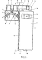
- a room spray dispenser 1 is attached to a door frame 6 and a trigger mechanism 2 to a door 5.
- a pivot lever 3 is shown in section as the trigger element, the functional end 3 1 of which is located above the room spray dispenser 1.
- the pivot lever 3 is fixed to a mounting housing 4.
- the cover 4 which is not visible in this drawing, is held by means of fastenings 4 ′′.
- FIG. 1 one can see the bores into which two wood screws 7 are screwed.
- the fastening housing 4 is fastened to the door 5 by means of wood screws 7, which are fastened through the recesses 8 are guided in.
- a dust cover 10 is inserted into the functional end 3 'of the swivel lever 3.
- the room spray dispenser 1 is provided with a hood 11 in which an opening 12 is formed, through which opening a nozzle 13 can be seen 1 shows a part of a locking lever 14, the surface of which is in contact with the functional end 3 1 of the pivot lever 3.
- a part of a clamping lever 15 is visible behind the functional end 3 'of the pivot lever 3.
- In the lower part of the hood 11 is part of a lock 16.
- a gap between the door 5 and the door frame 6 is designated by the number 17.
- FIG. 2 shows the top view of the device according to FIG. 1.
- a rear wall 18 is also fastened to the door frame 6 with wood screws 7
- Carrier walls 19 are formed in one piece with the rear wall 14 and run both vertically and horizontally perpendicular to the rear wall 18.
- Fastening elevations 21 are formed in one piece with the rear wall 18 and serve for the attachment and fastening of the hood 11.
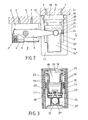
- FIG. 3 shows further parts of the room spray dispenser 1.
- a first pin 23 is mounted in a pressure lever 25, a second pin 24 being designed as a tiltable mounting of the pressure lever 25.
- the ends of this second pin 24 are fastened in the carrier walls 19.
- the functional end of the pressure lever 25 is designated by the reference number 25 '.
- One end of a tension spring 26 is pushed onto the first pin 23.
- a valve body 27 can also be seen in the lower part of FIG. 3.
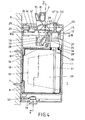
- Fig. 4 shows a vertical section through the room spray dispenser 1 perpendicular to the rear wall 18.
- further pins 28 can be seen in this drawing.
- One of these pins is used for the tiltable connection of the locking lever 14 with the pressure lever 25, another for rotatable connection of a lever 22 to the lower part of the tensioning lever 15 and the next for the rotatable mounting of the tensioning lever 15 in the support walls 19.
- the last pin 28 forms the holder for the lower end of the tension spring 26.
- a vessel 29 for the deodorant and / or Perfuming liquid is provided with a neck 29 'on which the valve body 27 is screwed.
- a tube 31 leads into the interior of the vessel 29 to the bottom, which of course is open at the bottom.
- an opening 32 for the locking part of the lock 16 is formed in one piece with the rear wall 18.
- a compression spring 33 is mounted between the locking lever 14 and the pressure lever 25.
- FIG. 5 shows a vertical section through the room spray dispenser 1, carried out parallel to the rear wall 18 Parts shown in this figure have already been described with reference to previous drawings.
- FIGS. 6 and 7 correspond to the upper part of FIG. 4 and serve to explain the functioning of the room spray dispenser 1.
- the tensioning lever 15 also jumped forward due to the force of the tension spring 26.
- the tension spring 26 also pulls the functional end 25 'of the pressure lever 25 downward, the functional end 25' presses on the upper button-like part of the valve body 27 and a mixture of the air and the liquid flows out of the nozzle 13 as a spray jet.
- the valve body 27 not only contains a valve, it also works like a pump. When the upper part of the valve body 27 is compressed, a certain amount of air is pressed into the vessel 29. The pressure of the air cushion acts on the liquid surface, and through the tube 31, a predetermined amount of the deodorant and / or perfume liquid is pressed into the valve body 27, mixed with the air and sprayed through the nozzle 13.
- FIG. 8 shows a simplified overall view of another exemplary embodiment of the trigger mechanism 2 with the room spray dispenser 1.
- both the room spray dispenser 1 and the fastening housing 39 for the trigger element are fastened to the door in the manner already described.
- the trigger element is designed as a two-armed trigger lever 34.
- the right support end 37 of the trigger lever 34 is supported on the door frame 6.
- the left functional end 36 of the trigger lever 34 is used to actuate the room spray dispenser 1, in which only the upper part of the clamping lever 15 is shown in simplified form because of the simplification.
- the number 35 symbolically represents the axis of rotation of the trigger lever 34.
- the room spray dispenser 1 with its levers corresponds to the room spray dispenser according to FIGS. 1 to 5. Its mode of operation is also the same as that described with reference to FIGS. 6 and 7.
- FIG. 9 shows the top view of the trigger lever 34.
- both the functional end 36 and the support end 37 are repeatedly illustrated.
- the circle 35 shows the position of the axis of rotation of the trigger lever 34.
- the mode of operation of the trigger lever 34 can be seen from FIG.
- the trigger lever 34 is provided at both ends with ridges 36 '. In this example, only the left elevation 36 'of the function end 36 a specific task, namely to operate the levers of the room spray dispenser 1 described above.
- the trigger lever 34 contains a spring, not shown. The task of this spring is to turn the trigger lever 34 when the door 5 is opened and, with the raised functional end 36 of the trigger lever 34, to press the locking lever 14 downward via the contact surface 14 ".
- the trigger lever 34 is designed symmetrically for use in doors to open either to the left inside or to the right inside, so the end referred to in this example as the support end 37 can be used in reverse as the function end 36.
- the fastening housing 39 is shown in section in Figure 10. It is with a Round vertical bearing 40, in which a pivot 38 of the trigger lever 34 is inserted.
- the bearing 40 can either encompass the pivot 38 without play so that it acts as a light brake, or it can with a known
- This pivot 38 is provided with a stop 41, which moves in an extension 42 of the bearing 40 during the actuation of the trigger lever 34.
- This stop 41 is intended to prevent the trigger lever 34 from getting out of the correct functional zone.
- the third variant of the trigger mechanism 2 and the arrangement of the room spray dispenser 1 is shown schematically in FIG. This variant is intended for the case that the door 5 moves outwards.
- the room spray dispenser 1 again corresponds to the embodiment described with reference to the first drawings.
- a trigger pin 44 is used as the trigger element, which in this example is formed in one piece with a part of the fastening housing 43.
- the fastening housing 43 with the trigger pin 44 is fastened to the door frame 6, the room spray dispenser 1 is arranged on the door 5. If one opens this door 5 to the outside and closes it again, the trigger pin 44 touches the lever system of the room spray dispenser 1 in the manner described above and doses the deodorant and / or perfuming liquid into the room.
- FIG. 13 shows, in partial section, the embodiment of the fastening housing 43 from FIG. 12.
- a recess 8 for fastening by means of a wood screw 7 is also shown.
- the trigger pin 44 is hollow and the fastening housing 43 with the trigger pin 44 is injection molded from plastic.
- FIGS. 14 to 16 corresponds to that according to FIGS. 2 to 7, however, the trigger element 3 (swivel lever) is replaced by the trigger 54 according to FIG. 15 and the upper contact surface 14 "of the locking lever 14 in the rear
- a pin 45 between the locking lever 14 and the pressure lever 25, which enables the aforementioned levers to move relative to one another, between the vertical support walls 19 and the tensioning lever 15 a pin 46 is arranged, around which the tensioning lever 15 can pivot.
- the tensioning lever 15 is provided with two locking cams 15 ", one locking cam 15" each being located on the inner side of the two-armed tensioning lever 15.
- FIG 14 which shows the tensioned state of the room spray dispenser
- this locking cam 15 blocks the locking lever 14 by engaging in a recess in this locking lever 14.
- this locking cam 15 “slides over the lower surface (or surfaces) of the locking lever 14, so that the tensioning lever 15 also moves into the relaxed position according to FIG. 16.
- this locking cam 15 presses the locking lever 14 back in the tense position according to FIG. 14
- Spring 26 tensioned and the spring 33 is subjected to pressure.
- a pin 47 is arranged in the interior of the tensioning lever 15 and is used for the movable mounting of the lever 22, a further pin 48 being mounted in the interior of the pressure lever 25 and guiding the upper end of the lever 22.
- the tension spring 26 Inside the pressure lever 25 there is also a pin 49 for holding the tension spring 26.
- the lower end of the tension spring 26 is fastened in or around a pin 50, this pin 50 being fastened in the vertical support walls 19.
- a bracket 51 for inserting the compression spring 33 is formed in the upper surface of the locking lever 14.
- This holder 51 is shaped like a cylinder, so that the compression spring 33 can either be pushed in, as shown, or can be pushed around the holder 51.
- the lower end of the compression spring 33 is placed on a holder 52.
- This holder 52 forms part of the pressure lever 25.
- the arrow 53 shows the direction of the pressure of the trigger 54 according to FIG. 15.
- the shutter 54 consists of a holder 55 and a slider 56.
- the functional part of the trigger 54 is designated 57. This functional part presses the tensioning lever 15 when tensioning in the direction of arrow 53 and when moving in the opposite direction of arrow 53 it slides over the upper contact surface 14 "of the locking lever 14 and thus triggers the spraying process
- the trigger 54 can be set in two parts, and the reference number 57 'denotes the inserted part of the slide 56.
- FIG. 17 and 18 show a solution according to the invention, in which a lever-like trigger 58 is used, which can be pulled with a cord 62.
- FIG. 16 shows a top view of the room spray dispenser 1
- FIG. 17 shows a side view of the lever-like trigger 58.
- a clamping surface of the lever-like trigger 58 is designated by the number 59.
- This clamping surface 59 has the same function 1, 2, 4 and 6, with the remaining parts of the solution according to FIGS. 17 and 18 (with the exception of the lever-like trigger 58) being the same as in the figures mentioned .
- the trigger 58 is therefore a constructive component of the room spray dispenser 1.
- the clamping surface 59 thus serves to take the lever 15 along during the clamping process.
- a trigger part 60 of the lever-like trigger 58 is intended for contacting the clamping lever 15.
- Side parts 61 of the lever-like trigger 58 are rotatably mounted with a pin 65 between the vertical support walls 19.
- the cord 62 is fixed in the fastening part 63 of the lever-like trigger 58 by means of a fastening 64 consisting, for example, of metal.
- the cord 62 is expediently made of an oil-free and elastic plastic and is provided for the folding of the room spray dispenser 1.
- the side parts 61 of the lever-like trigger 58 are each biased toward the front with a tension spring 66, so that a pull of the cord 62 tensions the tension spring 66 and prepares it for the next spraying process.
- the functional end 25 'of the pressure lever 25 is provided with a push button, the lower surface of which is adapted to the shape of the upper surface of the valve body 27.
- the room spray dispenser 1 can be arranged relatively far from the door 5 on a wall 69 and still be operated easily, for example by means of the said cord 62. Both the room spray dispenser and the trigger mechanism can be rationally manufactured using plastic technology known per se.
- the construction is particularly advantageous since the spray jet obtained is of great range, fine distribution and uniform density due to the pulsed actuation of the pump, without the need to use a propellant gas charge.
- the device is primarily intended for lavatory cabins and can ensure reliable odor removal or suppression.
- the room spray dispenser can be fastened on the door, on the door frame and also relatively far away from the door, the appropriate type of trigger element 3, 34, 44, 54, 58 being used, of course.
- trigger mechanisms 2 enable use with any given structural parts, the actuation of which is intended to bring the room spray dispenser 1 into operation.
Landscapes
- Chemical & Material Sciences (AREA)
- Dispersion Chemistry (AREA)
- Engineering & Computer Science (AREA)
- Mechanical Engineering (AREA)
- Containers And Packaging Bodies Having A Special Means To Remove Contents (AREA)
- Nozzles (AREA)
- Agricultural Chemicals And Associated Chemicals (AREA)
Priority Applications (1)
| Application Number | Priority Date | Filing Date | Title |
|---|---|---|---|
| AT84810141T ATE20520T1 (de) | 1983-04-15 | 1984-03-26 | Raumsprayspender. |
Applications Claiming Priority (2)
| Application Number | Priority Date | Filing Date | Title |
|---|---|---|---|
| CH202683 | 1983-04-15 | ||
| CH2026/83 | 1983-04-15 |
Publications (2)
| Publication Number | Publication Date |
|---|---|
| EP0127573A1 true EP0127573A1 (fr) | 1984-12-05 |
| EP0127573B1 EP0127573B1 (fr) | 1986-06-25 |
Family
ID=4224184
Family Applications (1)
| Application Number | Title | Priority Date | Filing Date |
|---|---|---|---|
| EP84810141A Expired EP0127573B1 (fr) | 1983-04-15 | 1984-03-26 | Générateur d'aérosol |
Country Status (7)
| Country | Link |
|---|---|
| US (1) | US4579261A (fr) |
| EP (1) | EP0127573B1 (fr) |
| JP (1) | JPS59199071A (fr) |
| AT (1) | ATE20520T1 (fr) |
| DE (2) | DE3460256D1 (fr) |
| HK (1) | HK71890A (fr) |
| SG (1) | SG69087G (fr) |
Cited By (12)
| Publication number | Priority date | Publication date | Assignee | Title |
|---|---|---|---|---|
| EP0315809A1 (fr) * | 1987-11-06 | 1989-05-17 | Bruno Sonderegger | Commutateur, en particulier pour un atomiseur pour une pièce |
| EP0401060A1 (fr) * | 1989-05-31 | 1990-12-05 | Conceptair Anstalt | Procédé et dispositif électrique, électronique et mécanique pour distribuer, doser ou diffuser, en phase liquide ou gazeuse, des arômes, médicaments et autres produits liquides ou visqueux |
| FR2647678A1 (fr) * | 1989-05-31 | 1990-12-07 | Conceptair Anstalt | Procede et dispositif pour diffuser des aromes, medicaments et autres produits volatils |
| FR2652282A1 (fr) * | 1989-09-28 | 1991-03-29 | Step Soc Tech Pulverisation | Procede et dispositif d'actionnement de pulverisateur a pompe. |
| US5016781A (en) * | 1986-10-21 | 1991-05-21 | Williams Trading B.V. | Device with replaceable container for atomizing liquid |
| WO1992020455A1 (fr) * | 1991-05-17 | 1992-11-26 | Rosaria Galli & C. S.A.S. | Systeme a actionnement mecanique automatique pour distributeurs atomiseurs de medicaments |
| WO1994004280A1 (fr) * | 1992-08-21 | 1994-03-03 | C W S International Ag | Diffuseur d'ambiance et sont utilisation preferee |
| WO1996003218A1 (fr) * | 1994-07-28 | 1996-02-08 | Aromatik (Uk) Limited | Dispositif servant a pulveriser un liquide en rafales |
| LT3701B (en) | 1993-12-16 | 1996-02-26 | Cws Ag | Room spray dispenser |
| TR28707A (tr) * | 1993-12-24 | 1997-01-27 | Cws Ag | Oda spreyi yayma düzenegi. |
| GB2340190A (en) * | 1998-06-30 | 2000-02-16 | Gary Roy Conway | Container for holding and dispensing liquids |
| US6377951B1 (en) | 1995-05-25 | 2002-04-23 | Punch Networks Corporation | On-line database updating network system and method |
Families Citing this family (6)
| Publication number | Priority date | Publication date | Assignee | Title |
|---|---|---|---|---|
| GB2259739B (en) * | 1991-06-29 | 1995-05-10 | Stag Limited | Actuator for dispensing apparatus |
| AU653701B3 (en) * | 1994-03-30 | 1994-10-06 | Vincenzo Salzano | Door actuated device for dispensing fluid from a container |
| US5677668A (en) * | 1994-06-10 | 1997-10-14 | Winner International Royalty Corporation | Vehicle accessory protection systems |
| FR2823728B1 (fr) * | 2001-04-23 | 2003-07-25 | Patrick Louis Chaumier | Dispositif support et distributeur de desodorisant aerosol pour les locaux de toilettes |
| NL1021979C2 (nl) | 2002-11-22 | 2004-05-26 | Sara Lee De Nv | Luchtverfrisser. |
| RU2359705C1 (ru) * | 2008-04-17 | 2009-06-27 | Олег Николаевич Жданов | Устройство для обработки воздуха |
Citations (2)
| Publication number | Priority date | Publication date | Assignee | Title |
|---|---|---|---|---|
| GB411055A (en) * | 1932-12-23 | 1934-05-31 | Juan Artigas Alart Casas | Improvements in or relating to spraying means |
| FR2448353A1 (fr) * | 1979-02-06 | 1980-09-05 | Teule Christian | Support declencheur automatique pour bombe aerosol |
Family Cites Families (8)
| Publication number | Priority date | Publication date | Assignee | Title |
|---|---|---|---|---|
| CA738270A (en) * | 1966-07-12 | Flanagan Peter | Dosing mechanisms | |
| FR1147976A (fr) * | 1956-01-16 | 1957-12-02 | Perfectionnement aux moyens destinés à assainir l'air des locaux | |
| GB933555A (en) * | 1961-02-28 | 1963-08-08 | Misani Gooderham & Young Ltd | A device for operating aerosol and like containers |
| US3033471A (en) * | 1961-08-11 | 1962-05-08 | Thurman W Horn | Door actuated spray device |
| US3214062A (en) * | 1965-02-23 | 1965-10-26 | Gen Time Corp | Actuating device for aerosol dispenser |
| US3805732A (en) * | 1972-10-04 | 1974-04-23 | W Reed | Intruder repeller and burglar alarm |
| US3827606A (en) * | 1973-06-27 | 1974-08-06 | Diamond Int Corp | Pump immobilizing means |
| US3980205A (en) * | 1975-03-20 | 1976-09-14 | Qantas Airways Limited | Aerosol can discharging apparatus |
-
1984
- 1984-03-26 AT AT84810141T patent/ATE20520T1/de not_active IP Right Cessation
- 1984-03-26 DE DE8484810141T patent/DE3460256D1/de not_active Expired
- 1984-03-26 EP EP84810141A patent/EP0127573B1/fr not_active Expired
- 1984-04-09 US US06/598,056 patent/US4579261A/en not_active Expired - Fee Related
- 1984-04-12 DE DE19843413810 patent/DE3413810A1/de not_active Withdrawn
- 1984-04-13 JP JP59073106A patent/JPS59199071A/ja active Granted
-
1987
- 1987-08-24 SG SG690/87A patent/SG69087G/en unknown
-
1990
- 1990-09-13 HK HK718/90A patent/HK71890A/xx not_active IP Right Cessation
Patent Citations (2)
| Publication number | Priority date | Publication date | Assignee | Title |
|---|---|---|---|---|
| GB411055A (en) * | 1932-12-23 | 1934-05-31 | Juan Artigas Alart Casas | Improvements in or relating to spraying means |
| FR2448353A1 (fr) * | 1979-02-06 | 1980-09-05 | Teule Christian | Support declencheur automatique pour bombe aerosol |
Cited By (15)
| Publication number | Priority date | Publication date | Assignee | Title |
|---|---|---|---|---|
| US5016781A (en) * | 1986-10-21 | 1991-05-21 | Williams Trading B.V. | Device with replaceable container for atomizing liquid |
| EP0315809A1 (fr) * | 1987-11-06 | 1989-05-17 | Bruno Sonderegger | Commutateur, en particulier pour un atomiseur pour une pièce |
| US5221025A (en) * | 1989-05-31 | 1993-06-22 | Conceptair Anstalt | Method and mechanical, electrical, or electronic apparatus for dispensing, issuing, or diffusing medicines, fragrances or other liquid or visous substances in the liquid phase or in the gaseous phase |
| EP0401060A1 (fr) * | 1989-05-31 | 1990-12-05 | Conceptair Anstalt | Procédé et dispositif électrique, électronique et mécanique pour distribuer, doser ou diffuser, en phase liquide ou gazeuse, des arômes, médicaments et autres produits liquides ou visqueux |
| FR2647678A1 (fr) * | 1989-05-31 | 1990-12-07 | Conceptair Anstalt | Procede et dispositif pour diffuser des aromes, medicaments et autres produits volatils |
| FR2652282A1 (fr) * | 1989-09-28 | 1991-03-29 | Step Soc Tech Pulverisation | Procede et dispositif d'actionnement de pulverisateur a pompe. |
| WO1992020455A1 (fr) * | 1991-05-17 | 1992-11-26 | Rosaria Galli & C. S.A.S. | Systeme a actionnement mecanique automatique pour distributeurs atomiseurs de medicaments |
| WO1994004280A1 (fr) * | 1992-08-21 | 1994-03-03 | C W S International Ag | Diffuseur d'ambiance et sont utilisation preferee |
| CH686661A5 (de) * | 1992-08-21 | 1996-05-31 | Cws Ag | Raumsprayspender und dessen bevorzugte Verwendung. |
| LT3701B (en) | 1993-12-16 | 1996-02-26 | Cws Ag | Room spray dispenser |
| TR28707A (tr) * | 1993-12-24 | 1997-01-27 | Cws Ag | Oda spreyi yayma düzenegi. |
| WO1996003218A1 (fr) * | 1994-07-28 | 1996-02-08 | Aromatik (Uk) Limited | Dispositif servant a pulveriser un liquide en rafales |
| US6377951B1 (en) | 1995-05-25 | 2002-04-23 | Punch Networks Corporation | On-line database updating network system and method |
| GB2340190A (en) * | 1998-06-30 | 2000-02-16 | Gary Roy Conway | Container for holding and dispensing liquids |
| GB2340190B (en) * | 1998-06-30 | 2000-07-19 | Gary Roy Conway | Container for holding and dispensing liquids |
Also Published As
| Publication number | Publication date |
|---|---|
| JPS59199071A (ja) | 1984-11-12 |
| DE3460256D1 (en) | 1986-07-31 |
| HK71890A (en) | 1990-09-21 |
| EP0127573B1 (fr) | 1986-06-25 |
| ATE20520T1 (de) | 1986-07-15 |
| JPH05104B2 (fr) | 1993-01-05 |
| DE3413810A1 (de) | 1984-10-18 |
| SG69087G (en) | 1988-02-19 |
| US4579261A (en) | 1986-04-01 |
Similar Documents
| Publication | Publication Date | Title |
|---|---|---|
| EP0127573B1 (fr) | Générateur d'aérosol | |
| DE19752332C1 (de) | Clipanlegegerät | |
| DE69932155T2 (de) | Vorrichtung zur abgabe einer kühlflüssigkeitsmenge und abgabeeinheit | |
| EP0084638B1 (fr) | Distributeur pour produits pâteux | |
| EP2218518B1 (fr) | Cartouche à plusieurs composants à usage unique | |
| DE102009049429B4 (de) | Schiebeanordnung | |
| DE2447426A1 (de) | Spruehvorrichtung | |
| EP0665321B1 (fr) | Dispositif d'injection d'eau pour fer à repasser à vapeur | |
| DE1500597A1 (de) | Tauchrohrzerstaeuber | |
| DE3817904C2 (fr) | ||
| DE2649915B2 (de) | Handhebel-Sprühvorrichtung | |
| DE69506481T2 (de) | Vordruck-Handpumpe zur Zerstäuben einer Flüssigkeit und Abgabevorrichtung mit einer solchen Pumpe | |
| DE1457440A1 (de) | Vorrichtung zum Zerstaeuben von Aerosolloesungen | |
| DE2744392A1 (de) | Vorrichtung zur abgabe eines fliessfaehigen stoffes zum zeitpunkt des gebrauchs | |
| DE2216525B2 (de) | Flüssigkeitszerstäuber | |
| EP0284907A1 (fr) | Distributeur de produits visqueux | |
| DE2425118A1 (de) | Dampfbuegeleisen | |
| DE1929844A1 (de) | Geraet zum Abgeben von Verbrauchsstoffen,z.B. Rasierkrem | |
| EP2442916A1 (fr) | Cartouche à plusieurs constituants à usage unique | |
| DE2412755A1 (de) | Spritzpistole | |
| DE102006036517A1 (de) | Abgabekopf für einen ein fließfähiges Medium unter Druck aufnehmenden Druckbehälter | |
| DE2631550B2 (de) | Spritzpistole mit Treibgasantrieb | |
| EP0331942A1 (fr) | Applicateur utilisant des cartouches | |
| CH453240A (de) | Auf eine Sprühdose aufsteckbare Betätigungsvorrichtung | |
| CH631512A5 (de) | Bremseinrichtung, insbesondere fuer tuerschliesser. |
Legal Events
| Date | Code | Title | Description |
|---|---|---|---|
| PUAI | Public reference made under article 153(3) epc to a published international application that has entered the european phase |
Free format text: ORIGINAL CODE: 0009012 |
|
| AK | Designated contracting states |
Designated state(s): AT BE CH DE FR GB IT LI LU NL SE |
|
| 17P | Request for examination filed |
Effective date: 19850228 |
|
| ITF | It: translation for a ep patent filed | ||
| GRAA | (expected) grant |
Free format text: ORIGINAL CODE: 0009210 |
|
| AK | Designated contracting states |
Kind code of ref document: B1 Designated state(s): AT BE CH DE FR GB IT LI LU NL SE |
|
| REF | Corresponds to: |
Ref document number: 20520 Country of ref document: AT Date of ref document: 19860715 Kind code of ref document: T |
|
| REF | Corresponds to: |
Ref document number: 3460256 Country of ref document: DE Date of ref document: 19860731 |
|
| ET | Fr: translation filed | ||
| PLBE | No opposition filed within time limit |
Free format text: ORIGINAL CODE: 0009261 |
|
| STAA | Information on the status of an ep patent application or granted ep patent |
Free format text: STATUS: NO OPPOSITION FILED WITHIN TIME LIMIT |
|
| 26N | No opposition filed | ||
| ITTA | It: last paid annual fee | ||
| EPTA | Lu: last paid annual fee | ||
| EAL | Se: european patent in force in sweden |
Ref document number: 84810141.6 |
|
| PGFP | Annual fee paid to national office [announced via postgrant information from national office to epo] |
Ref country code: SE Payment date: 19970306 Year of fee payment: 14 |
|
| PGFP | Annual fee paid to national office [announced via postgrant information from national office to epo] |
Ref country code: AT Payment date: 19970313 Year of fee payment: 14 |
|
| PGFP | Annual fee paid to national office [announced via postgrant information from national office to epo] |
Ref country code: NL Payment date: 19970331 Year of fee payment: 14 |
|
| PGFP | Annual fee paid to national office [announced via postgrant information from national office to epo] |
Ref country code: LU Payment date: 19970423 Year of fee payment: 14 |
|
| PGFP | Annual fee paid to national office [announced via postgrant information from national office to epo] |
Ref country code: BE Payment date: 19980325 Year of fee payment: 15 |
|
| PG25 | Lapsed in a contracting state [announced via postgrant information from national office to epo] |
Ref country code: LU Free format text: LAPSE BECAUSE OF NON-PAYMENT OF DUE FEES Effective date: 19980326 Ref country code: AT Free format text: LAPSE BECAUSE OF NON-PAYMENT OF DUE FEES Effective date: 19980326 |
|
| PG25 | Lapsed in a contracting state [announced via postgrant information from national office to epo] |
Ref country code: SE Free format text: LAPSE BECAUSE OF NON-PAYMENT OF DUE FEES Effective date: 19980327 |
|
| PG25 | Lapsed in a contracting state [announced via postgrant information from national office to epo] |
Ref country code: NL Free format text: LAPSE BECAUSE OF NON-PAYMENT OF DUE FEES Effective date: 19981001 |
|
| NLV4 | Nl: lapsed or anulled due to non-payment of the annual fee |
Effective date: 19981001 |
|
| EUG | Se: european patent has lapsed |
Ref document number: 84810141.6 |
|
| PG25 | Lapsed in a contracting state [announced via postgrant information from national office to epo] |
Ref country code: BE Free format text: LAPSE BECAUSE OF NON-PAYMENT OF DUE FEES Effective date: 19990331 |
|
| BERE | Be: lapsed |
Owner name: CWS A.G. Effective date: 19990331 |
|
| PGFP | Annual fee paid to national office [announced via postgrant information from national office to epo] |
Ref country code: GB Payment date: 20010321 Year of fee payment: 18 |
|
| REG | Reference to a national code |
Ref country code: GB Ref legal event code: IF02 |
|
| PG25 | Lapsed in a contracting state [announced via postgrant information from national office to epo] |
Ref country code: GB Free format text: LAPSE BECAUSE OF NON-PAYMENT OF DUE FEES Effective date: 20020326 |
|
| GBPC | Gb: european patent ceased through non-payment of renewal fee |
Effective date: 20020326 |
|
| PGFP | Annual fee paid to national office [announced via postgrant information from national office to epo] |
Ref country code: DE Payment date: 20030325 Year of fee payment: 20 |
|
| PGFP | Annual fee paid to national office [announced via postgrant information from national office to epo] |
Ref country code: FR Payment date: 20030327 Year of fee payment: 20 |
|
| PGFP | Annual fee paid to national office [announced via postgrant information from national office to epo] |
Ref country code: CH Payment date: 20030512 Year of fee payment: 20 |
|
| PG25 | Lapsed in a contracting state [announced via postgrant information from national office to epo] |
Ref country code: LI Free format text: LAPSE BECAUSE OF EXPIRATION OF PROTECTION Effective date: 20040325 Ref country code: CH Free format text: LAPSE BECAUSE OF EXPIRATION OF PROTECTION Effective date: 20040325 |
|
| REG | Reference to a national code |
Ref country code: CH Ref legal event code: PL |