EP0127585B1 - Compresseur d'air à chambres de compression opposées - Google Patents
Compresseur d'air à chambres de compression opposées Download PDFInfo
- Publication number
- EP0127585B1 EP0127585B1 EP84830064A EP84830064A EP0127585B1 EP 0127585 B1 EP0127585 B1 EP 0127585B1 EP 84830064 A EP84830064 A EP 84830064A EP 84830064 A EP84830064 A EP 84830064A EP 0127585 B1 EP0127585 B1 EP 0127585B1
- Authority
- EP
- European Patent Office
- Prior art keywords
- compressor
- air
- basement
- piston
- fact
- Prior art date
- Legal status (The legal status is an assumption and is not a legal conclusion. Google has not performed a legal analysis and makes no representation as to the accuracy of the status listed.)
- Expired
Links
- 230000006835 compression Effects 0.000 title claims description 20
- 238000007906 compression Methods 0.000 title claims description 20
- 239000003921 oil Substances 0.000 claims description 29
- 230000033001 locomotion Effects 0.000 claims description 15
- 230000000694 effects Effects 0.000 claims description 13
- 238000001816 cooling Methods 0.000 claims description 6
- 238000001914 filtration Methods 0.000 claims description 4
- 239000010687 lubricating oil Substances 0.000 claims description 3
- 230000003584 silencer Effects 0.000 claims description 2
- 238000009423 ventilation Methods 0.000 claims description 2
- 238000005461 lubrication Methods 0.000 description 4
- 230000007246 mechanism Effects 0.000 description 4
- 239000012530 fluid Substances 0.000 description 3
- 239000007788 liquid Substances 0.000 description 3
- 239000000463 material Substances 0.000 description 3
- 239000002245 particle Substances 0.000 description 3
- 238000010009 beating Methods 0.000 description 2
- 238000004891 communication Methods 0.000 description 2
- 230000000593 degrading effect Effects 0.000 description 2
- 238000007790 scraping Methods 0.000 description 2
- XAGFODPZIPBFFR-UHFFFAOYSA-N aluminium Chemical compound [Al] XAGFODPZIPBFFR-UHFFFAOYSA-N 0.000 description 1
- 229910052782 aluminium Inorganic materials 0.000 description 1
- 239000004411 aluminium Substances 0.000 description 1
- 230000005540 biological transmission Effects 0.000 description 1
- 238000004140 cleaning Methods 0.000 description 1
- 230000008878 coupling Effects 0.000 description 1
- 238000010168 coupling process Methods 0.000 description 1
- 238000005859 coupling reaction Methods 0.000 description 1
- 230000002939 deleterious effect Effects 0.000 description 1
- 238000010586 diagram Methods 0.000 description 1
- 238000007667 floating Methods 0.000 description 1
- 239000007789 gas Substances 0.000 description 1
- 230000005484 gravity Effects 0.000 description 1
- 238000010438 heat treatment Methods 0.000 description 1
- 230000001050 lubricating effect Effects 0.000 description 1
- 238000000034 method Methods 0.000 description 1
- 230000002093 peripheral effect Effects 0.000 description 1
- 230000009467 reduction Effects 0.000 description 1
- 238000007789 sealing Methods 0.000 description 1
- 125000006850 spacer group Chemical group 0.000 description 1
- 239000000725 suspension Substances 0.000 description 1
Images





Classifications
-
- F—MECHANICAL ENGINEERING; LIGHTING; HEATING; WEAPONS; BLASTING
- F04—POSITIVE - DISPLACEMENT MACHINES FOR LIQUIDS; PUMPS FOR LIQUIDS OR ELASTIC FLUIDS
- F04B—POSITIVE-DISPLACEMENT MACHINES FOR LIQUIDS; PUMPS
- F04B27/00—Multi-cylinder pumps specially adapted for elastic fluids and characterised by number or arrangement of cylinders
- F04B27/02—Multi-cylinder pumps specially adapted for elastic fluids and characterised by number or arrangement of cylinders having cylinders arranged oppositely relative to main shaft
-
- F—MECHANICAL ENGINEERING; LIGHTING; HEATING; WEAPONS; BLASTING
- F04—POSITIVE - DISPLACEMENT MACHINES FOR LIQUIDS; PUMPS FOR LIQUIDS OR ELASTIC FLUIDS
- F04B—POSITIVE-DISPLACEMENT MACHINES FOR LIQUIDS; PUMPS
- F04B39/00—Component parts, details, or accessories, of pumps or pumping systems specially adapted for elastic fluids, not otherwise provided for in, or of interest apart from, groups F04B25/00 - F04B37/00
- F04B39/0027—Pulsation and noise damping means
-
- F—MECHANICAL ENGINEERING; LIGHTING; HEATING; WEAPONS; BLASTING
- F04—POSITIVE - DISPLACEMENT MACHINES FOR LIQUIDS; PUMPS FOR LIQUIDS OR ELASTIC FLUIDS
- F04B—POSITIVE-DISPLACEMENT MACHINES FOR LIQUIDS; PUMPS
- F04B39/00—Component parts, details, or accessories, of pumps or pumping systems specially adapted for elastic fluids, not otherwise provided for in, or of interest apart from, groups F04B25/00 - F04B37/00
- F04B39/02—Lubrication
-
- F—MECHANICAL ENGINEERING; LIGHTING; HEATING; WEAPONS; BLASTING
- F04—POSITIVE - DISPLACEMENT MACHINES FOR LIQUIDS; PUMPS FOR LIQUIDS OR ELASTIC FLUIDS
- F04B—POSITIVE-DISPLACEMENT MACHINES FOR LIQUIDS; PUMPS
- F04B39/00—Component parts, details, or accessories, of pumps or pumping systems specially adapted for elastic fluids, not otherwise provided for in, or of interest apart from, groups F04B25/00 - F04B37/00
- F04B39/12—Casings; Cylinders; Cylinder heads; Fluid connections
Definitions
- the present invention refers to an air compressor with opposite compression chambers, having two pistons machined from one single structure, that is made reciprocate by a connecting rod, which is in turn connected with a crank on the rotating shaft of the engine.
- Compressors of the above type are already known from prior art, wherein air is sucked through a set of filters and silencer meanders, where it is compressed and then delivered toward user or storage tanks, in view of a successive use.
- GB-A-408 514 discloses a pump for compressing or exhausting air or gases which comprises two aligned pistons where a double-ended piston is operated by a connecting rod with a driving shaft.
- This equipment consists in a particular arrangement of a ball or roller bearing placed between the shaft and the connecting rod; said bearings are so mounted and arranged that the shaft together with its bearings can be withdrawn bodily from the connecting rod and from the casing. Therefore, this equipment solves problems of assemblying and disassemblying components of compressors.
- a compressor which allows to compress fluids without polluting them.
- Said compressor having a cylinder delimiting at least one compression chamber; said cylinder being fitted with fluid deliverying and intaking means.
- a movable piston operates in the cylinder and a crank mechanism is mechanically connected to the piston to move it in a reciprocating motion.
- Object of the present invention is to overcome said inconveniences of prior art.
- the present invention solves the problem of affording a compressor of the above described type, through which all functions involved in the above mentioned tasks are carried out in the best manner.
- the advantages achieved by means of a compressor according to the present invention are essentially the following: a better total efficiency due to the reduced passive volumes in comparison with the known compressors and owing to the fact that air included in said volume before intaking further air, is effective in shifting said piston; an even lubrication, owing to the fact that it is accomplished by means of oil vapours, developing from heating of oil contained inside the basement, thus preventing the movable parts from striking with liquid oil, said strike causing a slowdown of motion between said parts; said oil vapours, moreover, when flowing out of basement as a result of the thermal expansion, impregnate the air filter, thus increasing the filtering effect thereof; said lubrication can be obtained also by using an other lubricating method, that, although it exploits oil vapours as described above, provides the movable parts of compressor with liquid oil, by means of a structure capable of minimizing the striking effect against the mass of the oil contained in the basement; an appropriate ventilating system, suited to keep the compressor at the best operating temperature; said ventilation
- the compressor according to the present invention is distinguished from known compressors by the fact that it carries out its function better and has a longer working life.
- the compressor shown in Figure 1 is made-up of the assembly of the following structures: a case 1, made of non magnetical material, preferably of structural aluminium, accommodates an electrical motor M comprising a stator 2 and a rotor 3 with a shaft 71, which enters a plate 4, in which the case facing the compressor ends; a crank 5, made integral to the shaft 71 excentrically to the axis thereof, in order to drive a connecting rod 6, located between the said crank 5 and a piston 7, having two end parts, respectively, 8a and 8b, so shaped that each accommodates three seal rings; the seal rings belonging to said end part 8a are marked 9a, 10a, 11a; the seal rings belonging to the end part 8b are not represented, but they are identical to those just described. Furthermore, said piston 7 is provided with a recess 12, where said connecting rod 6 can move and a bore 13 is machined, suited to engage a pin 14 for said connecting rod 6.
- a basement 15 includes a cavity 16, delimited by four fixed walls 17, 18a, 18b and 19, placed, respectively, at top, by the two sides and at bottom of said cavity 16; said basement 15 being suited to contain a given quantity of lubricating oil, that, when the compressor is at standstill, reaches the level L as shown in Figure 4.
- Said wall 17 is provided with a threaded bore 20, where a tube 21 is screwed-in, which, through a radial bore 21b, brings the said cavity 16 in communication with the inner side 22a of an air filter 22, this latter being located inside a box 23, supported by said wall 17; said bore 21 b is suited to allow the vapours developing from oil contained inside the cavity 16 to expand toward the inside 22a of said filter 22, as to increase the filtering effect thereof and to lubricate the movable parts contained inside the compressor.
- Said box 23 is closed at top by a second plate 24 and by a third plate 25; a gasket 26 is interposed between the edges of the side walls of said box 23 and said plate 24, to ensure tightness.
- Said box 23 has a round relief 27, excentrical in comparison with said bore 20, suited to determine the position of said filter 22 inside said box 23, so that the outer diameter of said relief 27 is equal to the diameter of an internal part of said filter 22.
- Said second plate 24 has a central opening 30, where a ring-shaped element 31 is found, supported by three struts 32a, 32b and 32c, integral to said plate 24 and suited to keep said element 31 horizontal.
- a nut 33 is screwed-in on a threaded section 21a of tube 21; in order to fix said filter 22 with respect to said ring-shaped element 31.
- said second plate 24 has three concentric ribs 28 degrading from outside toward inside and grooves 29, aswell.
- Said third plate 25 has three concentric ribs 34, degrading from outside toward inside and grooves 35, arranged in the same way as the corresponding elements of said plate 24; moreover, said plate 25 is provided with spacers 36, arranged in such a way that air can flow between said ribs and said grooves of said plates 24 and 25, radially to said plates 24 and 25, that results in a reduction of noise generated by air sucked by the compressor; such air streams being conveyed toward the inner side of filter 22.
- the two walls 18a and 18b join, respectively, said cavity 16 with two cylinders 37a and 37b, externally finned, as to get cooled during their operation, and internally open toward said cavity 16, in order to accommodate the end parts 8a and 8b, respectively, of piston 7.
- Said cylinders 37a and 37b support, respectively, two heads 38a and 38b, identical and finned too, for cooling during the compressor operation, fixed to the relevant cylinders through connecting screws; between each head 38a (38b) and the relevant cylinder 37a (37b) being interposed a valve plate 39a (39b) and gaskets 40a (40b) and 41 a (41 b), arranged, respectively, between said plate 39a (39b) and said cylinder 37a (37b) and between the same plate and said head 38a (38b).
- the plate 39a (39b) is disclosed in EP-A-0 100 301, to the text thereof we are referring in view of a better understanding of structure and operation of said plate.
- each path starts from an inlet orifice 42a (42b) connecting said box 23 to a pipe 43a (43b), machined from the cylinder 37a (37b) and series connected to: a first bore 44a (44b), machined in the first gasket 40a (40b); a second bore 45a (45b) machined in the plate 39a (39b); a third bore 46a (46b) machined in the second gasket 41 a (41 b).
- Each of said paths comprises a cavity 47a (47b) machined in the head 38a (38b); a wall 48a (48b), that will be described in details later, delimits the inner side of cavity 47a (47b) in the head 38a (38b) thus enabling three slots 49a (49b), 50a (50b) and 51a (51b) to get in communication with said cavity; said slots being controlled by a suction valve 52a (52b) suited to open toward the inside of the cylinder under the effect of vacuum generated by the piston 7, moving from the top dead center toward the bottom dead center, thus intaking air to compress.
- a second path for compressed air starts from each cylinder 37a or 37b.
- This second path starts from three slots 53a (53b) 54a (54b) and 55a (55b) machined from plate 39a (39b) and controlled by a delivery valve 56a (56b) opening toward outside under the effect of pressure generated by the piston 7, moving from bottom dead center to top dead center, as to compress air.
- Said three slots face a cavity 57a (57b) existing inside the head 38a (38b), separated by said cavity 47a (47b) by wall 48a (48b), concentric to said head 38a (38b).
- Said cavity 57a (57b) communicates directly with a second cavity 58a (58b) machined from the same head 38a (38b), where a pipe opens, that consists of two bores 59a (59b) and 60a (60b) having the same diameter, and series connected one after another, which are machined, respectively, from said gasket 41a (41 b) and from said plate 39a (39b).
- Said bore 60a (60b) engages a tubular element 62a (62b) suited to convey the compressed air toward a delivery manifold 63, entered by said paths for compressed air, coming respectively, from cylinders 37a and 37b.
- Said tubular element 62a (62b) has an external profile 61a a (61 b), suited to enter a seat 70a (70b) foreseen inside said manifold 63, in order to fix both elements one to the other.
- Said manifold 63 is connected to a structure 64, that is fitted onto said cavity 16 and forms the front wall thereof.
- Seal rings 66a are provided to the end part of said tubular elements 62a (62b) which enter bores 69a (69b) machined from said manifold 63.
- Said manifold 63 has a threaded bore 68, where a tubular element, not shown, will be engaged, in order to deliver the compressed air to an user or to a tank.
- the volume comprised between the end part 8a (8b) of piston 7 and the suction valve 52a (52b) and the delivery valve 57a (57b) is very small, so the volumetric efficiency of the compressor turns out to be higher than the one of known compressors; furthermore, said compressed air included in said volume, during the suction stroke of each cylinder, supports the initial shifting of said piston 7, thus furtherly increasing the efficiency of the compressor according to the present invention.
- Said case 1 is shut at its rear part by a plate 65, provided with through holes for tie rods of the compressor; said plate 65 has a central hole 65a for supporting said shaft 71 of said motor M; a pulley 72 is splined on said shaft 71 ( Figure 2a, 2b) that drives through a first belt 73 a pulley 74, splined in turn on a shaft 75 supported by said plate 65; a third pulley 76 is splined on said shaft 75, that is coupled, through a second belt 77, to a fourth pulley 78, that is assembled to a shaft 79, coaxial to said shaft 71; on said shaft 79, a fan 80 is splined, that is made rotate at twice the rotating speed of shaft 71, as result of ratios between diameters of said four pulleys, in order to optimize the cooling effect.
- Said case 1 has longitudinal outer finnings, that improve the heat exchange toward outside during operation; four of these finnings are suited to be engaged with clamping elements of two structures 81a, 81 in order to fix said structures 81 a, 81 b to said case 1, and to provide two conduits for cooling air, that is delivered by said fan 80 to the compressor.
- the bottom of said case 1 supports a cover 83 for protection of belts 73, 77, pulleys 72, 74, 76, 78 and fan 80; said cover 83 is provided with a grating 82, in order to let air flow into the space inside said cover 83, and then to be conveyed toward the compressor through the two conduits inside the two structures 81 a (81 b).
- Said cover 83 is provided with a terminal strip 84, where the power supply cables of motor contained inside said case 1 end.
- a terminal strip 84 where the power supply cables of motor contained inside said case 1 end.
- said structure comprises: two feet 85a and 85b, connected by two tie rods 86 and 87; two elements 88a and 88b suited to enter a space included between the two fin rows of said case 1.
- the two structures shown in Figure 3 purposely arranged, support the compressor and can be disassembled for an easier handling.
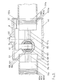
- the compressor according to the present invention consists of said basement 15, including said cavity 16 delimited by said fixed walls 17, 18a, 18b and 19, that are arranged as previously explained with reference to Figure 1; said basement 15, suited to contain a given oil quantity, in order to lubricate the movable parts of the compressor, said oil quantity being kept at a relatively steady level L.
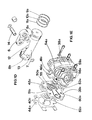
- Said plate 4, diagrammatically shown in Figure 5, has a first support 90 for said shaft 71; a crank 91 is connected to said shaft 71, as to rotate around the axis A of the same shaft.
- a thin tapered needle 92 suited to enter said oil sump contained inside said cavity 16 and to generate, by quickly turning together with said crank 91, an atmosphere of liquid state oil dispersed in particles, that joins the atmosphere of oil vapour existing inside said cavity 16 as a result of thermal effect; this allows the movable parts of the compressor to be provided with the lubricating oil quantity necessary for the correct operation of the same compressor; a pin 93, suited to transmit the motion of shaft 71 to two opposite pistons 94a and 94b, which enter, respectively, said two cylinders 37a and 37b, diagrammatically shown in Figure 4 and 5.
- Said pistons 94a and 94b are mutually connected by means of a sliding structure 95 comprising, essentially, a central bushing 96, suited to support integrally two arms 97a and 97b, which bear said pistons 94a and 94b, fixed to the corresponding arms by means of fastening screws.
- a sliding structure 95 comprising, essentially, a central bushing 96, suited to support integrally two arms 97a and 97b, which bear said pistons 94a and 94b, fixed to the corresponding arms by means of fastening screws.
- said piston 94a shown in partial cutaway view, is fixed to said supporting arm 97b by means of a screw 98a, the thread thereof is engaged in a threaded hole 99a in said arm 97a; in similar way the piston 94b is fixed to the corresponding supporting arm 97b; that enables both pistons 94a and 94b to be kept exactly coaxial.
- a seal ring 100a is foreseen on said arm 97a (and, obviously, on arm 97b) in order to prevent air leakages from the working chambers toward the basement 15 during the compression phases of pistons 94a (94b).
- Both pistons are provided with compression rings;
- Figure 4 shows the ring 101a, 102a and 103a only of the piston 94a, but it is understood that corresponding compression rings, not shown, are provided on the piston 94b.
- the last compression ring 103a is a scraper ring for scraping walls of cylinder 37a; it is understood, that an identical scraper ring, not shown, is provided on the piston 94b, for scraping walls of cylinder 37b.
- the bushing 96 has an inner bore 104, suited to accommodate a piston pin 105 coaxial to said bore 104 and to allow it sliding up and downwards along said bore 104.
- Said piston pin 105 has two countersinks 106 and 107, respectively, below and above, and a horizontal bore 108, suited to accommodate a bushing 109 of known type, in order to support the said pin 93.
- a bore 110 connects the said upper countersink 107 to a circular groove 111 in said bushing 109, as to let oil flow from the said countersink 107 and the said round groove 111, in order to lubricate the coupling of bushing 109 with pin 93.
- the rotation of shaft 71 of motor M shown in Figure 1, in the embodiment represented in Figure 4 and 5, makes the crank 91 rotate around its own axis A.
- the pin 93 describes a circular trajectory at steady speed rate about said axis A, and takes along the pin 105 in the same trajectory.
- the pin 105 can only move up or downwards, thus at every point of the trajectory described by the pin 93, the vertical component of velocity makes the pin 105 move up or downwards according to the direction of the two arrows A" and B" shown in Figure 4.
- the horizontal component of velocity of pin 93 shifts the bushing 96 to the right or to the left, according to the arrows A' and B'.
- Lubrication is accomplished, besides the oil vapours developing from oil contained inside the said basement 15 by the thermal effect, also by the needle 92 beating against the oil sump.
- the needle 92 brings oil particles in suspension at top of basement 15; these oil particles, together with the oil vapour, contribute to lubricate the movable parts of the compressor; the braking effect of the needle 92 beating against the oil bulk is minimized by the shape of said needle.
- Oil drops fallen onto the inner surface of cylinders 37a (37b) lubricate them, as to facilitate the relevant motion of pistons 94a and 94b, respectively; oil is then conveyed again into the basement 15 by the oil scrapers 103a fitted onto said pistons.
- the compressors shown and disclosed in FR-A-2 470 874 and GB-A-408 514 and that one shown in Figure 1 of the present application, are equipped with a double-ended piston driven by a shaft of a motor via a connection consisting of a pushing crank mechanism.
- crank mechanism In this type of crank mechanism the forces given by the crank (eccentric) to the connecting rod are transferred to the piston which moves in reciprocating motion; said forces having a component parallel to the direction of the motion and a component perpendicular thereto.
Landscapes
- Engineering & Computer Science (AREA)
- Mechanical Engineering (AREA)
- General Engineering & Computer Science (AREA)
- Compressor (AREA)
- Compressors, Vaccum Pumps And Other Relevant Systems (AREA)
Claims (7)
Priority Applications (2)
| Application Number | Priority Date | Filing Date | Title |
|---|---|---|---|
| AT84830064T ATE37743T1 (de) | 1984-03-12 | 1984-03-12 | Luftkompressor mit gegenueber liegenden verdichtungskammern. |
| DE8484830064T DE3474467D1 (en) | 1984-03-12 | 1984-03-12 | Air compressor with opposed compression chambers |
Applications Claiming Priority (1)
| Application Number | Priority Date | Filing Date | Title |
|---|---|---|---|
| IT8303365A IT1228584B (it) | 1983-03-11 | 1983-03-11 | Compressore d'aria a camere di compressione contrapposte |
Publications (3)
| Publication Number | Publication Date |
|---|---|
| EP0127585A2 EP0127585A2 (fr) | 1984-12-05 |
| EP0127585A3 EP0127585A3 (en) | 1985-08-28 |
| EP0127585B1 true EP0127585B1 (fr) | 1988-10-05 |
Family
ID=11105757
Family Applications (1)
| Application Number | Title | Priority Date | Filing Date |
|---|---|---|---|
| EP84830064A Expired EP0127585B1 (fr) | 1983-03-11 | 1984-03-12 | Compresseur d'air à chambres de compression opposées |
Country Status (2)
| Country | Link |
|---|---|
| EP (1) | EP0127585B1 (fr) |
| IT (1) | IT1228584B (fr) |
Cited By (1)
| Publication number | Priority date | Publication date | Assignee | Title |
|---|---|---|---|---|
| CN104806482A (zh) * | 2015-05-15 | 2015-07-29 | 朱益民 | 一种空压机用气缸盖总成 |
Families Citing this family (3)
| Publication number | Priority date | Publication date | Assignee | Title |
|---|---|---|---|---|
| EP0272229A1 (fr) * | 1986-12-19 | 1988-06-22 | Lyntex Limited | Groupe motocompresseur à piston |
| JPH1144289A (ja) * | 1997-07-29 | 1999-02-16 | Honda Motor Co Ltd | 往復動型コンプレッサ |
| JPH1144216A (ja) * | 1997-07-29 | 1999-02-16 | Honda Motor Co Ltd | 復動ピストン型コンプレッサ |
Family Cites Families (8)
| Publication number | Priority date | Publication date | Assignee | Title |
|---|---|---|---|---|
| GB392799A (en) * | 1931-09-15 | 1933-05-25 | Westinghouse Electric & Mfg Co | Improvements in or relating to fluid pressure unloading or releasing devices |
| GB408514A (en) * | 1933-09-15 | 1934-04-12 | Frank Hinman Pierpont | Improvements in or relating to pumps for compressing or exhausting air or gases |
| DE719387C (de) * | 1939-08-19 | 1942-04-07 | Mahle Kg | Sauggeraeuschdaempfer, insbesondere fuer Kompressoren |
| DE971682C (de) * | 1953-07-31 | 1959-03-12 | Fichtel & Sachs Ag | Schmiervorrichtung fuer die Doppelkolben und den Kurbelschleifenantrieb von Verdichtern |
| DE1149130B (de) * | 1960-06-21 | 1963-05-22 | Danfoss Ved Ing M Clausen | Schalldaempfer fuer Verdichter, insbesondere fuer Kleinkaeltemaschinen |
| DE1948081A1 (de) * | 1969-09-18 | 1971-04-01 | Wittig Gmbh Maschf Karl | Kompressor-Gehaeuse |
| EP0014085A1 (fr) * | 1979-01-30 | 1980-08-06 | Glynwed Group Services Limited | Groupe compresseur d'air |
| FR2470874B1 (fr) * | 1979-12-04 | 1986-08-22 | Abg Semca | Compresseur |
-
1983
- 1983-03-11 IT IT8303365A patent/IT1228584B/it active
-
1984
- 1984-03-12 EP EP84830064A patent/EP0127585B1/fr not_active Expired
Cited By (1)
| Publication number | Priority date | Publication date | Assignee | Title |
|---|---|---|---|---|
| CN104806482A (zh) * | 2015-05-15 | 2015-07-29 | 朱益民 | 一种空压机用气缸盖总成 |
Also Published As
| Publication number | Publication date |
|---|---|
| IT8303365A0 (it) | 1983-03-11 |
| EP0127585A2 (fr) | 1984-12-05 |
| IT1228584B (it) | 1991-06-24 |
| EP0127585A3 (en) | 1985-08-28 |
Similar Documents
| Publication | Publication Date | Title |
|---|---|---|
| US5632605A (en) | Multistage vacuum pump | |
| US5584675A (en) | Cylinder sleeve for an air compressor | |
| US4385875A (en) | Rotary compressor with fluid diode check value for lubricating pump | |
| US5951261A (en) | Reversible drive compressor | |
| CN1137097A (zh) | 改进了内部润滑系统的旋转斜盘型制冷压缩机 | |
| JPH0346675B2 (fr) | ||
| KR920009081B1 (ko) | 가동사판식 콤프레서 | |
| MXPA01001069A (es) | Compresor de espiral horizontal. | |
| US5888055A (en) | Connection between a refrigerant pipe and a suction muffler of a hermetic reciprocating compressor | |
| US4444549A (en) | Refrigerant compressor | |
| US5702236A (en) | Reciprocating piston type compressor having a discharge chamber with a plurality of pulsation attenuating subchambers | |
| CN1042564C (zh) | 密闭型电动压缩机 | |
| WO2011062402A2 (fr) | Compresseur | |
| US5052898A (en) | Bent axis compressor | |
| US3229901A (en) | Refrigerant compressor | |
| CA1097287A (fr) | Groupe compresseurs pour refrigerateurs | |
| US4326838A (en) | Swash plate type compressor for use in air-conditioning system for vehicles | |
| US6325602B1 (en) | Automotive vacuum pump | |
| CN112594153B (zh) | 一种节能气体无油压缩机及其多级压缩结构 | |
| US4431387A (en) | Hermetic refrigeration rotary motor-compressor | |
| EP0127585A2 (fr) | Compresseur d'air à chambres de compression opposées | |
| CN1168900C (zh) | 高压穹顶形压缩机 | |
| JP2004036583A (ja) | 圧縮機 | |
| US5322427A (en) | Rotary-blade air conditioner compressor for heavy-duty vehicle | |
| KR910004768B1 (ko) | 왕복식 압축기 및 그 조립방법 |
Legal Events
| Date | Code | Title | Description |
|---|---|---|---|
| PUAI | Public reference made under article 153(3) epc to a published international application that has entered the european phase |
Free format text: ORIGINAL CODE: 0009012 |
|
| AK | Designated contracting states |
Designated state(s): AT BE CH DE FR GB LI LU NL SE |
|
| PUAL | Search report despatched |
Free format text: ORIGINAL CODE: 0009013 |
|
| AK | Designated contracting states |
Designated state(s): AT BE CH DE FR GB LI LU NL SE |
|
| 17P | Request for examination filed |
Effective date: 19860218 |
|
| 17Q | First examination report despatched |
Effective date: 19870109 |
|
| GRAA | (expected) grant |
Free format text: ORIGINAL CODE: 0009210 |
|
| AK | Designated contracting states |
Kind code of ref document: B1 Designated state(s): AT BE CH DE FR GB LI LU NL SE |
|
| PG25 | Lapsed in a contracting state [announced via postgrant information from national office to epo] |
Ref country code: SE Effective date: 19881005 Ref country code: NL Effective date: 19881005 Ref country code: LI Effective date: 19881005 Ref country code: CH Effective date: 19881005 Ref country code: BE Effective date: 19881005 Ref country code: AT Effective date: 19881005 |
|
| REF | Corresponds to: |
Ref document number: 37743 Country of ref document: AT Date of ref document: 19881015 Kind code of ref document: T |
|
| REF | Corresponds to: |
Ref document number: 3474467 Country of ref document: DE Date of ref document: 19881110 |
|
| REG | Reference to a national code |
Ref country code: CH Ref legal event code: PL |
|
| NLV1 | Nl: lapsed or annulled due to failure to fulfill the requirements of art. 29p and 29m of the patents act | ||
| ET | Fr: translation filed | ||
| PG25 | Lapsed in a contracting state [announced via postgrant information from national office to epo] |
Ref country code: LU Free format text: LAPSE BECAUSE OF NON-PAYMENT OF DUE FEES Effective date: 19890331 |
|
| PLBE | No opposition filed within time limit |
Free format text: ORIGINAL CODE: 0009261 |
|
| STAA | Information on the status of an ep patent application or granted ep patent |
Free format text: STATUS: NO OPPOSITION FILED WITHIN TIME LIMIT |
|
| 26N | No opposition filed | ||
| PGFP | Annual fee paid to national office [announced via postgrant information from national office to epo] |
Ref country code: FR Payment date: 19940516 Year of fee payment: 11 |
|
| PGFP | Annual fee paid to national office [announced via postgrant information from national office to epo] |
Ref country code: GB Payment date: 19950303 Year of fee payment: 12 |
|
| PGFP | Annual fee paid to national office [announced via postgrant information from national office to epo] |
Ref country code: DE Payment date: 19950509 Year of fee payment: 12 |
|
| PG25 | Lapsed in a contracting state [announced via postgrant information from national office to epo] |
Ref country code: FR Free format text: LAPSE BECAUSE OF NON-PAYMENT OF DUE FEES Effective date: 19951130 |
|
| PG25 | Lapsed in a contracting state [announced via postgrant information from national office to epo] |
Ref country code: GB Effective date: 19960312 |
|
| REG | Reference to a national code |
Ref country code: FR Ref legal event code: ST |
|
| GBPC | Gb: european patent ceased through non-payment of renewal fee |
Effective date: 19960312 |
|
| PG25 | Lapsed in a contracting state [announced via postgrant information from national office to epo] |
Ref country code: DE Effective date: 19961203 |