EP0127601A2 - Affût mobile - Google Patents
Affût mobile Download PDFInfo
- Publication number
- EP0127601A2 EP0127601A2 EP84890059A EP84890059A EP0127601A2 EP 0127601 A2 EP0127601 A2 EP 0127601A2 EP 84890059 A EP84890059 A EP 84890059A EP 84890059 A EP84890059 A EP 84890059A EP 0127601 A2 EP0127601 A2 EP 0127601A2
- Authority
- EP
- European Patent Office
- Prior art keywords
- axis
- weapon barrel
- mobile carriage
- spars
- carriage according
- Prior art date
- Legal status (The legal status is an assumption and is not a legal conclusion. Google has not performed a legal analysis and makes no representation as to the accuracy of the status listed.)
- Granted
Links
Images

Classifications
-
- F—MECHANICAL ENGINEERING; LIGHTING; HEATING; WEAPONS; BLASTING
- F41—WEAPONS
- F41A—FUNCTIONAL FEATURES OR DETAILS COMMON TO BOTH SMALLARMS AND ORDNANCE, e.g. CANNONS; MOUNTINGS FOR SMALLARMS OR ORDNANCE
- F41A23/00—Gun mountings, e.g. on vehicles; Disposition of guns on vehicles
- F41A23/28—Wheeled-gun mountings; Endless-track gun mountings
- F41A23/32—Wheeled-gun mountings; Endless-track gun mountings with split trails
Definitions
- the invention relates to a mobile carriage with wheels for high and flat firearms, especially for grenade launchers.
- the weapon barrel is usually supported by a ball joint in a base plate that comes to rest directly on the ground.
- This base plate can in turn be connected for transport with a wheel axle having two wheels.
- This wheel axle has two spindle drives in the middle, specifically for the lateral and vertical adjustment of the tube. This straightening device attacks in the front area of the weapon barrel.
- a disadvantage is the relatively difficult connection from the axis to the base plate when the grenade launcher is to be transported. Furthermore, it is difficult to precisely align the gun barrel when it is supported by a ball, since the gun barrel is too free to move, which can cause canting and the like.
- the spars have bottom plates or spurs at their ends, which serve to support the recoil forces and dig into the ground in the course of several shots.
- a carriage With such a carriage, it is necessary that solid components are used, since the recoil forces are only introduced into the spars via relatively long levers.
- the space requirement for such a carriage is particularly high, since the spars protrude from the carriage in one direction, whereas the weapon barrel protrudes in the other direction.
- the gun barrel can be pivoted over the collapsible bars in order to make transportation easier. So that a correspondingly complicated side alignment axis must be provided again.
- the present invention has set itself the goal of creating a mobile carriage, which is suitable for both flat and high-powered firearms, for example grenade launchers, in which the end of the gun barrel facing away from the muzzle is only a short distance from the ground, an exact aiming of the gun barrel allowed, and avoids the disadvantages mentioned above.
- the mobile carriage according to the invention with wheels for steep and flat firearms, particularly for grenade launcher with a barrel, optionally with closure, if appropriate, a return and recuperator with ab photonder directly on the ground floor plate, the effective area in every Feuerstellun g the axis of the gun barrel cuts, and
- a height and side straightening device for the weapon barrel consists essentially in the fact that two separately guided, positively guided axes of rotation are provided, the axis of rotation for the height straightening of the weapon barrel possibly being rotatable together with the height straightening device about the axis of the side straightening device, and that at least two each Supporting spars are provided on the ground, two of which point apart as seen in the firing direction.
- the side straightening is completely independent of the height straightening, so that an exact straightening of the barrel is possible, whereby the axis of the gun barrel cuts the effective surface of the base plate supporting directly on the ground in every firing position , and two support bars are provided on the ground, which point in the firing direction, a particularly compact design is provided, which further allows the end of the weapon barrel to be brought as close as possible to the supporting floor.
- Hiebei can either be loaded via the muzzle, as is well known with grenade launchers, or according to the chamber system, as described, for example, in European Patent Application 66 161.
- a structurally particularly simple solution is obtained when the side direction axis for the weapon barrel is arranged in front of the height direction axis of the weapon barrel when viewed in the weft direction. If the lateral directional axis for the weapon barrel also serves as an axis of rotation for the spars, then a particularly direct transmission of the forces from the weapon barrel, or the return and recovery device can be ensured. This also avoids unnecessary leverage when transmitting forces, so that the moments that occur can be kept particularly low.
- a drive module e.g. Can be directly or directly linked to the motor vehicle, so unnecessarily high moments and forces are avoided even when the device is being transported, both on the drive module and on the carriage.
- the spars preferably carry at their ends, in particular wheels that are adjustable in height, for long-distance transport, then a mount that is particularly stable for transport is provided, by folding up, can also be easily brought into a stable firing position.
- the spars in particular for transporting the carriage, can be connected at their end regions by a crossbeam or the like, which is preferably articulated to a spar, the spars can be easily connected to one another, which is important both for transport and, if appropriate, for the Gun carriage in the firing position is particularly advantageous. If the crossbar is articulated on the spar, a particularly simple and labor-intensive connection or solution thereof can be achieved.
- At least one spar preferably a spindle at its end, a two-point support of the mount can be avoided in a particularly simple manner.
- the carriage With an eccentrically arranged spindle on the crossbeam, the carriage can be moved in front of a man from the transport position to the firing position and vice versa. It is only necessary that the eccentrically arranged spindle is set down against the ground, and a wheel of a spar is relieved by further actuation of the spindle, whereupon the spar can be pivoted easily and without contacting the ground from its transport position, the pivoting movement via the lever action of the spar can be carried out until the gun barrel is also aligned. Then the spindle is relieved and the crossbeam can be folded onto a spar.
- the spars preferably in the region of their articulation, support the base plate (s), which are supported directly on the subsurface, in particular spurs, a particularly simple and low-stress structural design of the mount is guaranteed.
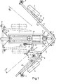
- Fi g. 1 a carriage in plan view and Fig. 2 in side view. Both in Fig. 1 and in Fig. 2, the carriage is shown in the firing position or dashed lines in the transport position.
- the mobile carriage has a weapon barrel 1 which is mounted in the lateral direction axis 4 via a joint piece 2 and the height direction axis 3.
- the spars 5 are also articulated on the lateral directional axis.
- the spars carry a two-part base plate 6 in the region of their articulation.
- the spars carry spindles 7, with which a horizontal alignment of the device is made possible, at the same time avoiding a two-point support.
- the bars always carry Weil a bearing block 8 in which axles for the wheels 9 for long-distance transport via steering knuckle 10 are attached. These wheels can be raised and lowered via axles, not shown, which are mounted in the bearing block.
- the side straightening device 11 is formed by the two arms 12, 13, which act on the spar on the one hand, and on the height straightening device on the other hand and can be changed in position via a spindle drive 14.
- the height adjustment device 15, as can be clearly seen in particular from FIG. 2, has a spindle drive 16 which engages on the weapon barrel via the arms 17, 18 or on the axis 19 via the support 19 for leveling the barrel.
- a crossbeam 20 is articulated on one of the two spars 5 and carries at its end a spindle 21 which can be lowered against the ground. In the position shown in dashed lines, the crossbar is connected via tabs 22, which are provided on the spar or on the crossbar, and a bolt 23. This creates a compact transport unit. 2, a coupling rod 24 for a motor vehicle is articulated on the lateral directional axis 4.
- a return and retrieval device 25 as can be seen particularly clearly in FIG. 1, is provided, it is mounted on the vertical direction axis.
- the side direction axis 4 is arranged in front of the height direction axis 3, by actuating the height direction device the weapon barrel can be pivoted, although, as can be seen particularly clearly in FIG.
- the effective area of the floor slab is to be understood as that area which cooperates directly with the floor, or an imaginary plane connecting it, which area can also be divided, curved or the like several times.
- the side leveling device is actuated so that the tube is precisely aligned, after which the gun is aligned and in the firing position.
Landscapes
- Engineering & Computer Science (AREA)
- General Engineering & Computer Science (AREA)
- Toys (AREA)
- Processing Of Stones Or Stones Resemblance Materials (AREA)
Applications Claiming Priority (2)
| Application Number | Priority Date | Filing Date | Title |
|---|---|---|---|
| AT117183 | 1983-04-01 | ||
| AT1171/83 | 1983-04-01 |
Publications (3)
| Publication Number | Publication Date |
|---|---|
| EP0127601A2 true EP0127601A2 (fr) | 1984-12-05 |
| EP0127601A3 EP0127601A3 (en) | 1986-10-01 |
| EP0127601B1 EP0127601B1 (fr) | 1990-04-25 |
Family
ID=3508143
Family Applications (1)
| Application Number | Title | Priority Date | Filing Date |
|---|---|---|---|
| EP84890059A Expired - Lifetime EP0127601B1 (fr) | 1983-04-01 | 1984-03-27 | Affût mobile |
Country Status (4)
| Country | Link |
|---|---|
| EP (1) | EP0127601B1 (fr) |
| DE (1) | DE3482053D1 (fr) |
| ES (1) | ES531046A0 (fr) |
| GR (1) | GR81893B (fr) |
Cited By (5)
| Publication number | Priority date | Publication date | Assignee | Title |
|---|---|---|---|---|
| GB2313178A (en) * | 1988-12-14 | 1997-11-19 | Vickers Shipbuilding & Eng | Field howitzers |
| GB2313179A (en) * | 1988-12-14 | 1997-11-19 | Vickers Shipbuilding & Eng | Field howitzers |
| US6024007A (en) * | 1988-12-14 | 2000-02-15 | Vickers Shipbuilding & Engineering Limited | Field howitzers |
| EP2110637A1 (fr) * | 2008-04-14 | 2009-10-21 | BAE Systems plc | Pièce d'artillerie de campagne |
| US8291809B2 (en) | 2008-04-14 | 2012-10-23 | Bae Systems Plc | Field gun |
Family Cites Families (3)
| Publication number | Priority date | Publication date | Assignee | Title |
|---|---|---|---|---|
| FR783790A (fr) * | 1934-03-28 | 1935-07-18 | Mortier rayé portatif d'infanterie | |
| FR799854A (fr) * | 1935-12-24 | 1936-06-22 | Perfectionnements aux obusiers ou mortiers | |
| US2444334A (en) * | 1945-02-14 | 1948-06-29 | American Ordnance Corp | Mortar mount |
-
1984
- 1984-03-12 GR GR74080A patent/GR81893B/el unknown
- 1984-03-27 DE DE8484890059T patent/DE3482053D1/de not_active Expired - Fee Related
- 1984-03-27 EP EP84890059A patent/EP0127601B1/fr not_active Expired - Lifetime
- 1984-03-28 ES ES531046A patent/ES531046A0/es active Granted
Cited By (8)
| Publication number | Priority date | Publication date | Assignee | Title |
|---|---|---|---|---|
| GB2313178A (en) * | 1988-12-14 | 1997-11-19 | Vickers Shipbuilding & Eng | Field howitzers |
| GB2313179A (en) * | 1988-12-14 | 1997-11-19 | Vickers Shipbuilding & Eng | Field howitzers |
| GB2313179B (en) * | 1988-12-14 | 1998-02-18 | Vickers Shipbuilding & Eng | Improvements in or relating to field howitzers |
| GB2313178B (en) * | 1988-12-14 | 1998-02-18 | Vickers Shipbuilding & Eng | Improvements in or relating to field howitzers |
| US6024007A (en) * | 1988-12-14 | 2000-02-15 | Vickers Shipbuilding & Engineering Limited | Field howitzers |
| FR2865532A1 (fr) * | 1988-12-14 | 2005-07-29 | Vickers Shipbuilding & Eng | Perfectionnement aux obusiers de campagne |
| EP2110637A1 (fr) * | 2008-04-14 | 2009-10-21 | BAE Systems plc | Pièce d'artillerie de campagne |
| US8291809B2 (en) | 2008-04-14 | 2012-10-23 | Bae Systems Plc | Field gun |
Also Published As
| Publication number | Publication date |
|---|---|
| ES8503431A1 (es) | 1985-02-16 |
| ES531046A0 (es) | 1985-02-16 |
| GR81893B (fr) | 1984-12-12 |
| EP0127601B1 (fr) | 1990-04-25 |
| EP0127601A3 (en) | 1986-10-01 |
| DE3482053D1 (de) | 1990-05-31 |
Similar Documents
| Publication | Publication Date | Title |
|---|---|---|
| EP2754989B1 (fr) | Dispositif et procédé de pointage d'un conteneur lanceur de missiles | |
| EP2875305B1 (fr) | Plateforme de tir, véhicule militaire comportant une plateforme de tir et procédé pour faire fonctionner une plateforme de tir | |
| DE4401587A1 (de) | Kampffahrzeug sowie Transportsystem zu seiner Verladung in Transportflugzeuge | |
| EP0450373B1 (fr) | Mécanisme de chargement pour canons, notamment pour obusiers blindés | |
| DE19713192C2 (de) | Trägerfahrzeug für eine Rohrwaffe mit einer Abstützvorrichtung | |
| EP0066161B1 (fr) | Système d'armement comportant un mortier monté sur un véhicule | |
| DE3603623C2 (fr) | ||
| EP0127601B1 (fr) | Affût mobile | |
| DE2532354A1 (de) | Abschussvorrichtung fuer die obere und die untere winkelgruppe | |
| DE2213598A1 (de) | Anhänger für Zugfahrzeuge | |
| DE2950218C2 (fr) | ||
| AT399221B (de) | Fahrbares geschütz, insbesondere fahrzeuggebundener granatwerfer | |
| DE2257679A1 (de) | Ladehilfe fuer panzerbordkanonen | |
| DE3644907C2 (de) | Leichtgeschütz mit erhöhungsabhängiger Anhebung des Rohrwiegenendes | |
| EP0013422B1 (fr) | Dispositif de support et de pointage d'une arme à tir indirect | |
| EP0128996B1 (fr) | Affût pour une pièce d'artillerie | |
| DE102013111269A1 (de) | Stützanordnung und Verfahren zum Abstützen eines Objekts | |
| EP0491271B1 (fr) | Système d'arme comportant quatre canons | |
| DE728213C (de) | Minenwerfer | |
| DE1553982A1 (de) | Ruestsatz fuer rueckstossgetriebene,fernlenkbare Flugkoerper mit einer mit einem Fahrzeug verbundenen,hoehenrichtbaren Plattform | |
| AT398842B (de) | Geschosswaffe, insbesondere granatwerfer | |
| DE1188477B (de) | Granatwerfer | |
| DE2713633A1 (de) | Munitionszufuehrungsvorrichtung fuer ein feldartilleriegeschuetz | |
| EP0627608B1 (fr) | Dispositif de refoulement automatique pour projectiles d'artillerie | |
| EP0117901A2 (fr) | Traîneau |
Legal Events
| Date | Code | Title | Description |
|---|---|---|---|
| PUAI | Public reference made under article 153(3) epc to a published international application that has entered the european phase |
Free format text: ORIGINAL CODE: 0009012 |
|
| AK | Designated contracting states |
Designated state(s): BE CH DE FR GB IT LI LU NL SE |
|
| 17P | Request for examination filed |
Effective date: 19850515 |
|
| PUAL | Search report despatched |
Free format text: ORIGINAL CODE: 0009013 |
|
| AK | Designated contracting states |
Kind code of ref document: A3 Designated state(s): BE CH DE FR GB IT LI LU NL SE |
|
| 17Q | First examination report despatched |
Effective date: 19880210 |
|
| RAP1 | Party data changed (applicant data changed or rights of an application transferred) |
Owner name: NORICUM MASCHINENBAU UND HANDEL GESELLSCHAFT M.B.H |
|
| GRAA | (expected) grant |
Free format text: ORIGINAL CODE: 0009210 |
|
| AK | Designated contracting states |
Kind code of ref document: B1 Designated state(s): BE CH DE FR GB IT LI LU NL SE |
|
| ITF | It: translation for a ep patent filed | ||
| GBT | Gb: translation of ep patent filed (gb section 77(6)(a)/1977) | ||
| REF | Corresponds to: |
Ref document number: 3482053 Country of ref document: DE Date of ref document: 19900531 |
|
| ET | Fr: translation filed | ||
| PLBE | No opposition filed within time limit |
Free format text: ORIGINAL CODE: 0009261 |
|
| STAA | Information on the status of an ep patent application or granted ep patent |
Free format text: STATUS: NO OPPOSITION FILED WITHIN TIME LIMIT |
|
| PG25 | Lapsed in a contracting state [announced via postgrant information from national office to epo] |
Ref country code: GB Effective date: 19910327 |
|
| PG25 | Lapsed in a contracting state [announced via postgrant information from national office to epo] |
Ref country code: SE Effective date: 19910328 |
|
| PG25 | Lapsed in a contracting state [announced via postgrant information from national office to epo] |
Ref country code: LU Free format text: LAPSE BECAUSE OF NON-PAYMENT OF DUE FEES Effective date: 19910331 Ref country code: LI Effective date: 19910331 Ref country code: CH Effective date: 19910331 Ref country code: BE Effective date: 19910331 |
|
| 26N | No opposition filed | ||
| BERE | Be: lapsed |
Owner name: NORICUM MASCHINENBAU UND HANDEL G.M.B.H. Effective date: 19910331 |
|
| PG25 | Lapsed in a contracting state [announced via postgrant information from national office to epo] |
Ref country code: NL Effective date: 19911001 |
|
| NLV4 | Nl: lapsed or anulled due to non-payment of the annual fee | ||
| GBPC | Gb: european patent ceased through non-payment of renewal fee | ||
| PG25 | Lapsed in a contracting state [announced via postgrant information from national office to epo] |
Ref country code: FR Effective date: 19911129 |
|
| REG | Reference to a national code |
Ref country code: CH Ref legal event code: PL |
|
| PG25 | Lapsed in a contracting state [announced via postgrant information from national office to epo] |
Ref country code: DE Effective date: 19920101 |
|
| REG | Reference to a national code |
Ref country code: FR Ref legal event code: ST |
|
| EUG | Se: european patent has lapsed |
Ref document number: 84890059.3 Effective date: 19911009 |