EP0127602A2 - Meuble, en particulier bureau à élément escamotable verticalement - Google Patents
Meuble, en particulier bureau à élément escamotable verticalement Download PDFInfo
- Publication number
- EP0127602A2 EP0127602A2 EP84890078A EP84890078A EP0127602A2 EP 0127602 A2 EP0127602 A2 EP 0127602A2 EP 84890078 A EP84890078 A EP 84890078A EP 84890078 A EP84890078 A EP 84890078A EP 0127602 A2 EP0127602 A2 EP 0127602A2
- Authority
- EP
- European Patent Office
- Prior art keywords
- carriage
- furniture
- cover plate
- lowerable
- furniture according
- Prior art date
- Legal status (The legal status is an assumption and is not a legal conclusion. Google has not performed a legal analysis and makes no representation as to the accuracy of the status listed.)
- Withdrawn
Links
Images

Classifications
-
- A—HUMAN NECESSITIES
- A47—FURNITURE; DOMESTIC ARTICLES OR APPLIANCES; COFFEE MILLS; SPICE MILLS; SUCTION CLEANERS IN GENERAL
- A47B—TABLES; DESKS; OFFICE FURNITURE; CABINETS; DRAWERS; GENERAL DETAILS OF FURNITURE
- A47B17/00—Writing-tables
- A47B17/04—Writing-tables with secret or fireproof compartments ; Trays or the like countersunk in the table top and obturable, e.g. by means of a roller or sliding shutter
Definitions
- the invention relates to a piece of furniture with an upper cover plate, in particular a desk with a writing surface, at least some of which can be lowered into the interior of the furniture transversely to its surface extension, and with a flexible surface element that can be pushed into a position closing the opening, such as a roller blind or the like .
- a disadvantage of the training known from DE-B-66 784 is that because of the guidance of the retractable worktop in oblique grooves in the raised position behind the worktop and in the lowered position in front of the worktop there is a free space, which this plate is at best as a carrier usable for typewriters.
- the roller bar begins to move forward immediately from the beginning of the lowering of the worktop, so that higher objects placed on the plate can cause collisions between these objects and the roller bar.
- a disadvantage of the furniture according to AT-B-43 714 and DE-B-66 784 is the fact that the arrangement of the actuating mechanism for the movable plate or the roller beam limits the possibilities of designing the foot part of the furniture.
- DE-B-384 476 which describes a piece of furniture with the features of the preamble of claim 1, a lowerable desk worktop is provided, over which, after being lowered, a roller shutter can be pulled forward.
- DE-B-384 476 does not show how the desk worktop should be lowered or how this worktop is guided.
- the invention therefore has for its object to provide a piece of furniture of the type mentioned, in which the movable part of the cover plate, e.g. the desk top, can easily be lowered and raised again.
- both the movable part of the plate and the advancing surface element should be able to be provided with drives without restricting the design of the base of the furniture.
- the furniture according to the invention is characterized in that the lowerable part of the The cover plate rests on a carriage guided on or in the side walls of the furniture, that the guides for the carriage comprise guide grooves inclined to the vertical on or in the side walls of the furniture, into which guide pins of the carriage fitted with sliding pins or rollers engage, and that the space of the piece of furniture, into which the lowerable part of the cover plate can be lowered, is surrounded all around by essentially vertical walls, on which the lowerable part of the cover plate is guided laterally when lowering.
- a vertically movable part or a plurality of such parts can be lowered in the cover plate together with the objects standing or lying thereon, the opening thus created at the top of the furniture, which can extend over part or all of the cover plate , can be closed by the closing element.
- the invention can be implemented particularly cheaply in desks, wherein in addition to a fixed desk top part, a lowerable part or a lowerable plate part can be provided on both sides of the fixed part.
- the length of the guides means either the total length of the guides (e.g. guide grooves) or the effective length of the guides due to the adjustable stops.
- an embodiment of the invention is advantageous in which the lower end position of the carriage or the lowerable part of the cover plate is assigned a limit switch which switches off the drive of the carriage and triggers the advancement of the flexible surface element.
- a switch which can be actuated by the flexible surface element in its open position is provided and which controls the raising of the lowerable part of the cover plate in its upper end position which is flush with the cover plate, in particular the desk plate, and which The drive for the end element switches off.
- At least one motor-operated cable or chain hoist is provided for actuating the carriage.
- This embodiment has the advantage that the lowerable part of the cover plate cannot be pressed down from its upper end position even under load by appropriate pretensioning of the cable or chain hoist.
- rollers attached to the carriage are preferably provided between the carriage and the lowerable part of the cover plate freely rotatable.
- This embodiment is characterized by a particular ease of movement when moving the lowerable part of the cover plate, since the relative movement occurring when the part is moved between the part and the carriage is practically frictionless by the rollers.
- the closure element can also be simply pulled or pushed manually into the closed position, as is known per se for roller beams.
- motor drives can also be provided. In the sense of a small space requirement, it has proven itself within the scope of the invention if linear motors are provided for actuating the lowerable part of the cover plate and / or the roller blind.
- electric motors in particular climbing motors and push rods actuated by them, are provided as linear motors, the push rods of the drive for the carriage being coupled to the latter via the cable or chain hoists and the push rod for the closure element this is coupled directly.
- pneumatic or hydraulic pressure medium cylinders can also be used as linear motors.
- a further improvement of the guidance of the trolley for the lowerable part of the cover plate results if rolling guide rollers are provided on the side of the trolley for the lowerable part of the cover plate on the inner surface of the side walls of the furniture, the axes of rotation of which are perpendicular to the longitudinal extension of the guide grooves for the trolley.
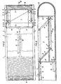
- a desk 1 has, as the upper cover plate, a desk plate 2 which is fastened to a frame-like frame with side walls 3 and 4, the desk standing on the floor via feet or bases not shown in detail.
- FIG. 2 shows in particular, the rigid part of the desk top 2 does not extend over the entire length of the desk 1. Rather, in the exemplary embodiment shown, lowerable tabletop parts 5 are provided on both sides of the rigid desk top 2, which in the normal position (raised position) with the Surface of the rigid desk top 2 are flush.
- the lowerable parts 5 rest, as can be seen in particular from FIG. 3, with the interposition of rollers 6 on a frame-like carriage 7.
- carriages 7 are provided for both lowerable parts 5.
- Each carriage 7 is guided via slide pins or slide rollers 8 in guides provided in or on the side walls 3 and 4 of the desk frame, such as guide rails or guide grooves 9.
- the guide grooves 9 run obliquely to Rigid desk top level 2.
- the extent of the stroke movement of the movable part 5 of the desk plate 2 can 9 or assigned by the guides in a simple manner by the length of the guide grooves, optionally adjustable 'stops are limited.
- linear motors 14 and 15 are provided, the push rods 16 of which are coupled to the cables 10 and 11 of both carriages 7.
- freely rotatable guide rollers 17 can be provided thereon, which roll on the inner surfaces of the side walls 3 and 4 of the desk 1 and whose axes are aligned perpendicular to the longitudinal direction of the guide grooves 9.
- a switch 18 which on the one hand shuts off the drive for the cables 10 and 11 and on the other hand triggers the advancement of the flexible surface element designed as a roller blind 19 in the exemplary embodiment shown into the closed position (FIG. 2, left).
- a linear motor 20, the push rod 20 'of which is connected to one end 21 of the roller blind 19, is put into operation.
- the roller blind is guided in the side walls 3 and 4 of the desk 1 in such a way that its top is aligned with the top of the rigid plate 2 in the closed position. This results in a continuous work surface.
- roller blind 19 If the roller blind 19 is in its open position (FIG. 2, right), in which the upper end of the roller blind 19 comes to lie approximately above the wall 13, the lower end 21 of the roller blind 19 actuates a further switch 22 (FIG. 1), which turns off the linear motor 20 for the roller blind 19 and triggers the lifting of the movable part 5.
- chain hoists can also be provided.
- Pressure-actuated cylinders can also be used as linear motors.
Landscapes
- Support Devices For Sliding Doors (AREA)
- Tables And Desks Characterized By Structural Shape (AREA)
Applications Claiming Priority (2)
| Application Number | Priority Date | Filing Date | Title |
|---|---|---|---|
| AT1647/83 | 1983-05-04 | ||
| AT164783A AT384157B (de) | 1983-05-04 | 1983-05-04 | Moebel |
Publications (2)
| Publication Number | Publication Date |
|---|---|
| EP0127602A2 true EP0127602A2 (fr) | 1984-12-05 |
| EP0127602A3 EP0127602A3 (fr) | 1987-10-14 |
Family
ID=3517942
Family Applications (1)
| Application Number | Title | Priority Date | Filing Date |
|---|---|---|---|
| EP84890078A Withdrawn EP0127602A3 (fr) | 1983-05-04 | 1984-05-04 | Meuble, en particulier bureau à élément escamotable verticalement |
Country Status (2)
| Country | Link |
|---|---|
| EP (1) | EP0127602A3 (fr) |
| AT (1) | AT384157B (fr) |
Families Citing this family (1)
| Publication number | Priority date | Publication date | Assignee | Title |
|---|---|---|---|---|
| CN106175129A (zh) * | 2016-08-09 | 2016-12-07 | 宁波力芯科信息科技有限公司 | 一种智能课桌及基于智能课桌的异地学习匹配方法 |
Family Cites Families (7)
| Publication number | Priority date | Publication date | Assignee | Title |
|---|---|---|---|---|
| DE66784C (de) * | G. schubert in Herischdorf b. Warmbrunn i. Schlesien, Villa Toepert | Schreibtisch mit versenkbarer Tischplatte | ||
| DE519091C (de) * | 1931-02-23 | Koch Albert | Mit Rolladen verschliessbarer Schreibtisch und mit durch Eigengewicht herabsenkbarer Platte | |
| DE290511C (fr) * | ||||
| AT43714B (de) * | 1908-10-10 | 1910-08-25 | Leopold Fischer | Schreibtisch mir versenkbarer Platte. |
| DE382476C (de) * | 1922-09-12 | 1923-10-03 | Aloys Gruenewald | Schreibtisch |
| DE661978C (de) * | 1936-12-18 | 1938-07-01 | Karl Gruner | Moebel, insbesondere Schreibtisch, mit einer im Zargenraum versenkbar gelagerten Schreibplatte und einer rolladenartigen Tischplatte |
| US2509806A (en) * | 1947-05-05 | 1950-05-30 | George W Byars | Combination table and desk |
-
1983
- 1983-05-04 AT AT164783A patent/AT384157B/de not_active IP Right Cessation
-
1984
- 1984-05-04 EP EP84890078A patent/EP0127602A3/fr not_active Withdrawn
Also Published As
| Publication number | Publication date |
|---|---|
| AT384157B (de) | 1987-10-12 |
| ATA164783A (de) | 1987-03-15 |
| EP0127602A3 (fr) | 1987-10-14 |
Similar Documents
| Publication | Publication Date | Title |
|---|---|---|
| EP0682156B2 (fr) | Conteneur | |
| DE2848648A1 (de) | Elektroschaltzellen-hubvorrichtung | |
| DE3213983A1 (de) | Vorrichtung zum handhaben von transport- bzw. lagereinheiten, insbesondere in hochregal-blocklagersystemen | |
| DE3878759T2 (de) | Schiebedachkonstruktion, insbesondere verandadach. | |
| DE2005446B2 (de) | Plattenbeladevorrichtung | |
| DE2616495A1 (de) | Schiebetuer fuer kuehlraeume | |
| DE916212C (de) | Schreibtisch mit versenkbarer Bueromaschine | |
| EP0127602A2 (fr) | Meuble, en particulier bureau à élément escamotable verticalement | |
| DE102015114413A1 (de) | Bausatz für eine Boots-Parkvorrichtung, insbesondere für den Einbau in ein Boots-Parkhaus und Boots-Bock hierfür | |
| DE1291574B (de) | Abdeckvorrichtung fuer die Fuehrungsbahnen an Werkzeugmaschinen od. dgl. | |
| DE19801856A1 (de) | Verfahren und Vorrichtung zum Beschicken und Entnehmen von Behältern in ein bzw. aus einem Regal | |
| DE1230683B (de) | Fahrzeugschiebedach | |
| DE2210161A1 (de) | Schrankbett | |
| DE1622982B2 (de) | Vorrichtung zum Betrachten photographischer Aufnahmen, insbesondere von Röntgenaufnahmen | |
| DE2706108C2 (de) | Verfahren und Einrichtung zur Lageänderung beweglicher Abschnitte in Bühnenböden | |
| DE2301823C3 (de) | Umsetzeranlage mit einem Umsetzer für ein Regalförderzeug | |
| DE19537995A1 (de) | Vorrichtung zum Überführen schwerer Lasten | |
| DE2444534A1 (de) | Paletteneinschubgeraet fuer regalbedienungsgeraete und gabelstapler | |
| DE3611505C2 (fr) | ||
| DE2330461B2 (de) | Aufhänge- und Führungsvorrichtung für ein Vertikalschiebetor | |
| DE1210693B (de) | Mittels seitlicher Zuege bewegbares Schiebedach, insbesondere fuer Kraftfahrzeuge | |
| DE1303206C2 (de) | Vorrichtung zum seitwaertigen befoerdern und absetzen von fahrzeugen in garagen od.dgl., insbesondere von kraftfahrzeugen | |
| DE2305837C3 (de) | Fahrzeug für den Transport von Stahlbetonraumzellen, insbesondere von Fertiggaragen | |
| DE2307711A1 (de) | Hebebuehne fuer kraftfahrzeuge | |
| DE2453003C3 (de) | Vorrichtung an einem mit einem Liegeflächenrahmen versehenen Krankenbett zum Transportieren von Nachttischschränken, Beistelltischen oder dergleichen |
Legal Events
| Date | Code | Title | Description |
|---|---|---|---|
| PUAI | Public reference made under article 153(3) epc to a published international application that has entered the european phase |
Free format text: ORIGINAL CODE: 0009012 |
|
| AK | Designated contracting states |
Designated state(s): BE CH DE FR GB IT LI LU NL |
|
| PUAL | Search report despatched |
Free format text: ORIGINAL CODE: 0009013 |
|
| AK | Designated contracting states |
Kind code of ref document: A3 Designated state(s): BE CH DE FR GB IT LI LU NL |
|
| STAA | Information on the status of an ep patent application or granted ep patent |
Free format text: STATUS: THE APPLICATION IS DEEMED TO BE WITHDRAWN |
|
| 18D | Application deemed to be withdrawn |
Effective date: 19880415 |
|
| RIN1 | Information on inventor provided before grant (corrected) |
Inventor name: SVOBODA, JOHANN |