EP0127703A1 - Einrichtung zum Positionieren eines beweglichen Bauteiles gegenüber einem ortsfesten Bauteil - Google Patents
Einrichtung zum Positionieren eines beweglichen Bauteiles gegenüber einem ortsfesten Bauteil Download PDFInfo
- Publication number
- EP0127703A1 EP0127703A1 EP83201708A EP83201708A EP0127703A1 EP 0127703 A1 EP0127703 A1 EP 0127703A1 EP 83201708 A EP83201708 A EP 83201708A EP 83201708 A EP83201708 A EP 83201708A EP 0127703 A1 EP0127703 A1 EP 0127703A1
- Authority
- EP
- European Patent Office
- Prior art keywords
- plate
- locking
- head
- crib
- fixed
- Prior art date
- Legal status (The legal status is an assumption and is not a legal conclusion. Google has not performed a legal analysis and makes no representation as to the accuracy of the status listed.)
- Withdrawn
Links
Images
Classifications
-
- B—PERFORMING OPERATIONS; TRANSPORTING
- B23—MACHINE TOOLS; METAL-WORKING NOT OTHERWISE PROVIDED FOR
- B23Q—DETAILS, COMPONENTS, OR ACCESSORIES FOR MACHINE TOOLS, e.g. ARRANGEMENTS FOR COPYING OR CONTROLLING; MACHINE TOOLS IN GENERAL CHARACTERISED BY THE CONSTRUCTION OF PARTICULAR DETAILS OR COMPONENTS; COMBINATIONS OR ASSOCIATIONS OF METAL-WORKING MACHINES, NOT DIRECTED TO A PARTICULAR RESULT
- B23Q3/00—Devices holding, supporting, or positioning work or tools, of a kind normally removable from the machine
- B23Q3/155—Arrangements for automatic insertion or removal of tools, e.g. combined with manual handling
- B23Q3/157—Arrangements for automatic insertion or removal of tools, e.g. combined with manual handling of rotary tools
-
- B—PERFORMING OPERATIONS; TRANSPORTING
- B23—MACHINE TOOLS; METAL-WORKING NOT OTHERWISE PROVIDED FOR
- B23Q—DETAILS, COMPONENTS, OR ACCESSORIES FOR MACHINE TOOLS, e.g. ARRANGEMENTS FOR COPYING OR CONTROLLING; MACHINE TOOLS IN GENERAL CHARACTERISED BY THE CONSTRUCTION OF PARTICULAR DETAILS OR COMPONENTS; COMBINATIONS OR ASSOCIATIONS OF METAL-WORKING MACHINES, NOT DIRECTED TO A PARTICULAR RESULT
- B23Q16/00—Equipment for precise positioning of tool or work into particular locations not otherwise provided for
- B23Q16/001—Stops, cams, or holders therefor
-
- Y—GENERAL TAGGING OF NEW TECHNOLOGICAL DEVELOPMENTS; GENERAL TAGGING OF CROSS-SECTIONAL TECHNOLOGIES SPANNING OVER SEVERAL SECTIONS OF THE IPC; TECHNICAL SUBJECTS COVERED BY FORMER USPC CROSS-REFERENCE ART COLLECTIONS [XRACs] AND DIGESTS
- Y10—TECHNICAL SUBJECTS COVERED BY FORMER USPC
- Y10T—TECHNICAL SUBJECTS COVERED BY FORMER US CLASSIFICATION
- Y10T483/00—Tool changing
- Y10T483/17—Tool changing including machine tool or component
- Y10T483/1733—Rotary spindle machine tool [e.g., milling machine, boring, machine, grinding machine, etc.]
- Y10T483/1736—Tool having specific mounting or work treating feature
- Y10T483/1738—Tool head
Definitions
- the invention relates to a device for positioning a mobile member relative to a fixed member, for example a device for positioning the tool head support plate of a machine tool crib in the head change position.
- machining centres machine tools known as machining centres.
- large tool heads are sometimes used, each removably mounted on plates carried by chains.
- the tools of each head can either be single tools (one per head) for milling, reaming or other operations, or multiple tools for drilling, tapping or other operations.
- the head On termination of the machining operation by one or more of its tools, the head is returned to the tool crib, from which the next required head is withdrawn, carrying other tools for further machining operations.
- Each head is commonly mounted on guides on a plate which is rigid with the crib chains, and when the plate laterally reaches a position corresponding with the working zone, suitable pusher means transfer the head on to a corresponding support which supports the head during the machining carried out by its tools.
- the same pusher means On termination of the machining operation or operations, the same pusher means re-engage the head, and again transfer it on to the plate which has remained in a waiting position, after which the chain continues its rotation, under command or programming, in order to move a new head into a lateral position corresponding with the working zone, to which the new head is then transferred.
- the operations involving the transfer of the heads to and from their working zone must be carried out with maximum precision and rapidity.
- the head can be hindered in its transfer from the plate to the support and vice versa, these latter being in exact mutually corresponding positions when the chain stops in order to present the head required for the programmed machining.
- the head plate must therefore be correctly locked and located so as to enable the head to traverse in both directions without the danger of hindrance.
- the object of the invention is to propose a system for locking the head support plate in the exact position in which the transfer of the head to the fixed member, ie the driving head, must take place.
- the positioning device is in the form of a member which hooks on to a stem on the plate, and by the action of a cylinder exerts on it a pull which locks it against fixed abutments of the crib, to ensure precision and repeatability of the positioning by locking said system and taking-up any slack. This results in considerable simplicity of construction and uniqueness of the system in that it uses a single actuator.
- a device for positioning a mobile member relative to a fixed member such as the support for the plates which support the tool heads of a machine tool crib, in the head change position in which a head support plate is carried by a crib chain provided with rollers sldable along fixed guides, characterised by comprising first means for contacting the plate and for locking it along the head transfer axis, and second means for anchoring the plate against fixed crib positions; said first means comprising members for contacting plate abutments and for locking these latter against said members; said second means comprising members for pulling plate abutments against said fixed positions.
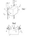
- FIG. 10 show only a portion of the crib chain 10 on which a tool head 11 is mounted. Both the chain 10 and head 11 are in fact of conventional type, known to every expert of the art. Only this chain portion 10 will be considered, which portion being situated at the point in which the head change is to take place.
- the term "head change" signifies the condition in which the head 11 is to be transferred on to the drive head of the machine in order to machine work pieces by means of the tools carried by the head 11, these not being shown for simplicity.
- the chain 10 carries rollers 12 designed to slide along fixed guides 13 which stabilise its advancing movement.
- the head 11 can be connected to the plate by means of dovetail guides, which are not shown as they are of known type.
- the plate 15 is provided with a straight bar 16 and a pull stem 17 with a head 18, for the purpose described hereinafter.
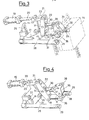
- Figures 3 and 4 show the positioning device according to the invention, which is mounted on the machine within the chain 10, in a position corresponding with that portion shown in Figures 1 and 2, ie at the point in which the head 11 is to be transferred from the plate 15 to the drive head.
- This device comprises a fixed cylinder 19, of which the rod 20 is pivoted at 21 to a lever 22 and carries a plate 24 pivoted at 23.
- the plate 24 is pivoted on a fixed pin 25 and comprises a slot 26 in which the pin 27 of two parallel rods 28 slides, these being chamfered at their end 29.
- To the lever 22 there are also pivoted at 32 and 33 two pull rods 30 and 31, of which the first carries a clamp 35 pivoted at 34, while the second 31 has its end configured as a fork 36 with its arms turned inwards.
- the clamp 35 is of substantially triangular section with one vertex pivoted at 34 to the pull rod 30, another vertex pivoted at 37 to a fixed point, and the third vertex extending in the form of a toothed appendix 38.
- the operation of the device is as follows.
- the tool head 11 required for carrying out one or more machining operations on a work piece is moved to its point of transfer from the crib to the machine drive head by rotating the chain 10 which carries it.
- the positioning device is in its "open" state of Figure 4, ie in which the rod 20 is retracted, with the result that the clamp 35 is in a rotated position in which the teeth 38 are raised, the pull rod 31 is in an advanced position, and the rods 28 are slightly retracted.
- the chain 10 it is possible for the chain 10 to move until the head 11 is positioned in its required change position, ie for transfer from the crib to the drive head.
- the straight bar 16 of the plate 15 makes contact with the chamfered portions 29 of the rods 28; the clamp 35 descends in order to force the straight bar 16 against the chamfered portions 29, so horizontally positioning the plate 15 carrying the head 11; the fork 36 of the arm 31 exerts a pulling action on the pull stem 17, so taking-up the slack of the rollers 12 by forcing them against their guides 13.
- the plate 15 is in its correct plane, aligned with the drive head guides so that the head 11 can be rapidly and reliably transferred from the crib to the drive head.
Landscapes
- Engineering & Computer Science (AREA)
- Mechanical Engineering (AREA)
- Automatic Tool Replacement In Machine Tools (AREA)
- Jigs For Machine Tools (AREA)
Applications Claiming Priority (1)
| Application Number | Priority Date | Filing Date | Title |
|---|---|---|---|
| ITTO1982U53972U IT8253972U1 (it) | 1982-11-22 | 1982-11-22 | Dispositivo di posizionamento di un organo mobile rispetto ad un organo fisso |
Publications (1)
| Publication Number | Publication Date |
|---|---|
| EP0127703A1 true EP0127703A1 (de) | 1984-12-12 |
Family
ID=11286196
Family Applications (1)
| Application Number | Title | Priority Date | Filing Date |
|---|---|---|---|
| EP83201708A Withdrawn EP0127703A1 (de) | 1982-11-22 | 1983-12-01 | Einrichtung zum Positionieren eines beweglichen Bauteiles gegenüber einem ortsfesten Bauteil |
Country Status (3)
| Country | Link |
|---|---|
| US (1) | US4562919A (de) |
| EP (1) | EP0127703A1 (de) |
| IT (1) | IT8253972U1 (de) |
Families Citing this family (10)
| Publication number | Priority date | Publication date | Assignee | Title |
|---|---|---|---|---|
| IT8253891V0 (it) * | 1982-11-05 | 1982-11-05 | Comau Spa | Sistema di riferimento e bloccaggio di organi mobili in senso bidirezionale in una posizione ripetitiva |
| US4695047A (en) * | 1986-10-14 | 1987-09-22 | Carr Lane Roemheld Manufacturing Co., Inc. | T-slot hydraulic clamp system |
| US4947980A (en) * | 1989-03-02 | 1990-08-14 | American Telephone And Telegraph Company | Method and apparatus for stopping and clamping substrates |
| IT1241047B (it) * | 1990-03-14 | 1993-12-29 | Metalprogetti Di Santicchi Augusto & C. | Dispositivo di aggiustamento della posizione di arresto dei nastri di trasporto impiegati sugli impianti trasportatori aerei. |
| US5346050A (en) * | 1993-01-28 | 1994-09-13 | Fleetwood Systems, Inc. | Carton conveying apparatus |
| US6068104A (en) * | 1997-11-26 | 2000-05-30 | Jenoptik Aktiengesellschaft | Device for securing a moving object at a destination |
| DE10043429A1 (de) * | 2000-09-04 | 2002-03-14 | Hilti Ag | Bohrvorrichtung |
| DE10316941A1 (de) * | 2003-04-12 | 2004-11-11 | Arzneimittel Gmbh Apotheker Vetter & Co. Ravensburg | Transporteinrichtung |
| US9833019B2 (en) * | 2014-02-13 | 2017-12-05 | Rai Strategic Holdings, Inc. | Method for assembling a cartridge for a smoking article |
| CN108927463A (zh) * | 2018-06-26 | 2018-12-04 | 嘉善缔嘉装饰材料有限公司 | 一种板材的定位装置 |
Citations (6)
| Publication number | Priority date | Publication date | Assignee | Title |
|---|---|---|---|---|
| DE2026221A1 (de) * | 1970-05-29 | 1971-12-09 | Bw Weber Verwaltungs Gmbh | Werkzeugmaschine mit einer Bearbeitungs einheit fur auswechselbare Mehrspindelkopfe |
| US3817391A (en) * | 1972-05-22 | 1974-06-18 | Kearney & Trecker Corp | Tool storage magazine |
| DE2324082A1 (de) * | 1970-09-04 | 1974-11-28 | Walter Prof Dipl Ing Guttropf | Bearbeitungszentrum |
| US4034465A (en) * | 1975-06-09 | 1977-07-12 | The Cross Company | Machining center and method of operation |
| DE2753801A1 (de) * | 1976-12-02 | 1978-06-08 | Bendix Machine Tool | Verfahren und vorrichtung zum auswechseln von werkzeugkoepfen an werkzeugmaschinen |
| DE3115481A1 (de) * | 1981-04-16 | 1982-11-04 | Bernhard Steinel Werkzeugmaschinenfabrik GmbH u. Co, 7730 Villingen-Schwenningen | Werkstueckpaletten-speicher fuer ein bearbeitungszentrum |
Family Cites Families (10)
| Publication number | Priority date | Publication date | Assignee | Title |
|---|---|---|---|---|
| US3482831A (en) * | 1967-09-11 | 1969-12-09 | Leland F Blatt | Toggle action jaw type gripper |
| GB1182892A (en) * | 1968-05-31 | 1970-03-04 | Pressen Und Scherenbau Erfurt | Improvements in and relating to Clamping Devices. |
| GB1277034A (en) * | 1968-07-17 | 1972-06-07 | Shinkikaigiken Company Ltd | Stop device in machine tool |
| US3567208A (en) * | 1969-06-06 | 1971-03-02 | Leland F Blatt | Toggle action jaw type gripper |
| CH531396A (de) * | 1970-05-29 | 1972-12-15 | Bw Weber Verwaltungs Gmbh | Werkzeugmaschine mit einer Bearbeitungseinheit zum Aufnehmen von auswechselbaren Mehrspindelköpfen |
| FR2425918A2 (fr) * | 1978-01-31 | 1979-12-14 | Mavilor Manuf Vilebrequins | Cadre vertical mobile support de tete d'entrainement d'outils avec moyen de guidage par rapport au bati, pour toutes machines-outils d'utilisation generale |
| JPS5577403A (en) * | 1978-11-28 | 1980-06-11 | Honda Motor Co Ltd | Gang head replacement type machine tool |
| US4216572A (en) * | 1978-12-07 | 1980-08-12 | Honda Giken Kogyo Kabushiki Kaisha | Replaceable gang head machine tool |
| DE2852846C2 (de) * | 1978-12-07 | 1985-03-07 | Eksperimental'nyj naučno-issledovatel'skij institut metallorežuščich stankov, Moskau/Moskva | Werkzeugmaschine mit automatisch gesteuerten Werkzeug- und Palettenwechslern |
| US4484775A (en) * | 1982-08-23 | 1984-11-27 | The United States Of America As Represented By The Secretary Of The Army | Adjustable smooth action linkage gripper mechanism |
-
1982
- 1982-11-22 IT ITTO1982U53972U patent/IT8253972U1/it unknown
-
1983
- 1983-11-15 US US06/552,064 patent/US4562919A/en not_active Expired - Fee Related
- 1983-12-01 EP EP83201708A patent/EP0127703A1/de not_active Withdrawn
Patent Citations (6)
| Publication number | Priority date | Publication date | Assignee | Title |
|---|---|---|---|---|
| DE2026221A1 (de) * | 1970-05-29 | 1971-12-09 | Bw Weber Verwaltungs Gmbh | Werkzeugmaschine mit einer Bearbeitungs einheit fur auswechselbare Mehrspindelkopfe |
| DE2324082A1 (de) * | 1970-09-04 | 1974-11-28 | Walter Prof Dipl Ing Guttropf | Bearbeitungszentrum |
| US3817391A (en) * | 1972-05-22 | 1974-06-18 | Kearney & Trecker Corp | Tool storage magazine |
| US4034465A (en) * | 1975-06-09 | 1977-07-12 | The Cross Company | Machining center and method of operation |
| DE2753801A1 (de) * | 1976-12-02 | 1978-06-08 | Bendix Machine Tool | Verfahren und vorrichtung zum auswechseln von werkzeugkoepfen an werkzeugmaschinen |
| DE3115481A1 (de) * | 1981-04-16 | 1982-11-04 | Bernhard Steinel Werkzeugmaschinenfabrik GmbH u. Co, 7730 Villingen-Schwenningen | Werkstueckpaletten-speicher fuer ein bearbeitungszentrum |
Also Published As
| Publication number | Publication date |
|---|---|
| US4562919A (en) | 1986-01-07 |
| IT8253972V0 (it) | 1982-11-22 |
| IT8253972U1 (it) | 1984-05-22 |
Similar Documents
| Publication | Publication Date | Title |
|---|---|---|
| US4274801A (en) | Machine tool with an adjustable mechanism for fixing and displacing a workpiece relative to a tool | |
| US4930332A (en) | Apparatus for exchanging tool for bending machine | |
| EP2138247B1 (de) | Fertigungsanlage mit Biegepresse | |
| US4304041A (en) | Automatic tool changer for forging machines | |
| US4577389A (en) | Automatic tool changer | |
| US4562919A (en) | Device for positioning a mobile member relative to a fixed member | |
| SU858550A3 (ru) | Металлорежущий станок | |
| EP1447154B1 (de) | Stanzpresse | |
| DE60112098T2 (de) | Werkzeugmaschine | |
| US4629384A (en) | Transfer and locator of workpieces for a gang machine | |
| SU712017A3 (ru) | Многопозиционна машина дл обработки металлов | |
| US5370212A (en) | Automatic pallet changer method and apparatus | |
| DE3627866C2 (de) | ||
| US3451125A (en) | Automatic tool changer | |
| EP0281664B1 (de) | Palettenwechseleinrichtung für Werkzeugmaschine | |
| WO1984000915A1 (en) | Tool changer mechanism for machining centers | |
| EP0003027B1 (de) | Automatischer Werkzeugwechsler für eine Werkzeugmaschine | |
| DE3004861C2 (de) | Transfervorrichtung | |
| GB2154480A (en) | Method and equipment for automatically changing tools on hobbing machines | |
| SU633711A1 (ru) | Устройство дл автоматич ской смены инструмента на токарном станке | |
| DE2416474A1 (de) | Werkzeugmaschine | |
| US4540084A (en) | Device for automatically transferring printed circuit base plates from the loading to the printing zone | |
| DE2440368C3 (de) | Revolverdrehautomat mit zwei Werkstückspindeln | |
| US4509235A (en) | Tool changer | |
| DE3501113C2 (de) |
Legal Events
| Date | Code | Title | Description |
|---|---|---|---|
| PUAI | Public reference made under article 153(3) epc to a published international application that has entered the european phase |
Free format text: ORIGINAL CODE: 0009012 |
|
| AK | Designated contracting states |
Designated state(s): AT BE CH DE FR GB LI LU NL SE |
|
| XX | Miscellaneous (additional remarks) |
Free format text: PRIORITAET: 22.11.82 IT 5397282. DIE FRIST VON ARTIKEL 87(1)EPUE GILT GEMAESS REGEL 85(2)EPUE ALS GEWAHRT (SIEHE AUCH ABL 1/84,16). |
|
| 17P | Request for examination filed |
Effective date: 19850515 |
|
| 17Q | First examination report despatched |
Effective date: 19860721 |
|
| R17C | First examination report despatched (corrected) |
Effective date: 19870416 |
|
| STAA | Information on the status of an ep patent application or granted ep patent |
Free format text: STATUS: THE APPLICATION IS DEEMED TO BE WITHDRAWN |
|
| 18D | Application deemed to be withdrawn |
Effective date: 19871027 |
|
| RIN1 | Information on inventor provided before grant (corrected) |
Inventor name: CATTANI, ALBERTO |