EP0127799A2 - Autoclave et procédé pour assembler des lentilles composites - Google Patents
Autoclave et procédé pour assembler des lentilles composites Download PDFInfo
- Publication number
- EP0127799A2 EP0127799A2 EP84105335A EP84105335A EP0127799A2 EP 0127799 A2 EP0127799 A2 EP 0127799A2 EP 84105335 A EP84105335 A EP 84105335A EP 84105335 A EP84105335 A EP 84105335A EP 0127799 A2 EP0127799 A2 EP 0127799A2
- Authority
- EP
- European Patent Office
- Prior art keywords
- autoclave
- lens
- pressure
- support members
- lens support
- Prior art date
- Legal status (The legal status is an assumption and is not a legal conclusion. Google has not performed a legal analysis and makes no representation as to the accuracy of the status listed.)
- Withdrawn
Links
- 239000002131 composite material Substances 0.000 title claims abstract description 23
- 238000000034 method Methods 0.000 title claims abstract description 12
- 230000006835 compression Effects 0.000 claims description 10
- 238000007906 compression Methods 0.000 claims description 10
- 239000004033 plastic Substances 0.000 claims description 8
- 229920003023 plastic Polymers 0.000 claims description 8
- 238000010438 heat treatment Methods 0.000 claims description 7
- 210000005069 ears Anatomy 0.000 claims description 6
- 230000033001 locomotion Effects 0.000 claims description 6
- 239000012530 fluid Substances 0.000 claims description 5
- 244000182067 Fraxinus ornus Species 0.000 claims 1
- 230000003287 optical effect Effects 0.000 abstract description 5
- 239000011521 glass Substances 0.000 description 10
- 238000004519 manufacturing process Methods 0.000 description 5
- 239000000463 material Substances 0.000 description 5
- IJGRMHOSHXDMSA-UHFFFAOYSA-N Atomic nitrogen Chemical compound N#N IJGRMHOSHXDMSA-UHFFFAOYSA-N 0.000 description 4
- 239000010408 film Substances 0.000 description 4
- 238000005299 abrasion Methods 0.000 description 2
- 239000000853 adhesive Substances 0.000 description 2
- 230000001070 adhesive effect Effects 0.000 description 2
- 230000005540 biological transmission Effects 0.000 description 2
- 238000013461 design Methods 0.000 description 2
- 238000001035 drying Methods 0.000 description 2
- 239000001307 helium Substances 0.000 description 2
- 229910052734 helium Inorganic materials 0.000 description 2
- SWQJXJOGLNCZEY-UHFFFAOYSA-N helium atom Chemical compound [He] SWQJXJOGLNCZEY-UHFFFAOYSA-N 0.000 description 2
- 238000003475 lamination Methods 0.000 description 2
- 229910052751 metal Inorganic materials 0.000 description 2
- 239000002184 metal Substances 0.000 description 2
- 238000012986 modification Methods 0.000 description 2
- 230000004048 modification Effects 0.000 description 2
- 229910052757 nitrogen Inorganic materials 0.000 description 2
- 238000004806 packaging method and process Methods 0.000 description 2
- 238000003825 pressing Methods 0.000 description 2
- 238000012545 processing Methods 0.000 description 2
- 239000000126 substance Substances 0.000 description 2
- 229910001369 Brass Inorganic materials 0.000 description 1
- 229910000831 Steel Inorganic materials 0.000 description 1
- 229910045601 alloy Inorganic materials 0.000 description 1
- 239000000956 alloy Substances 0.000 description 1
- 230000004075 alteration Effects 0.000 description 1
- 229910052782 aluminium Inorganic materials 0.000 description 1
- XAGFODPZIPBFFR-UHFFFAOYSA-N aluminium Chemical compound [Al] XAGFODPZIPBFFR-UHFFFAOYSA-N 0.000 description 1
- 239000010951 brass Substances 0.000 description 1
- 239000000969 carrier Substances 0.000 description 1
- 238000004140 cleaning Methods 0.000 description 1
- 239000003086 colorant Substances 0.000 description 1
- 230000002301 combined effect Effects 0.000 description 1
- 238000007796 conventional method Methods 0.000 description 1
- 230000000694 effects Effects 0.000 description 1
- 239000013013 elastic material Substances 0.000 description 1
- 229920001971 elastomer Polymers 0.000 description 1
- 239000007789 gas Substances 0.000 description 1
- 230000001771 impaired effect Effects 0.000 description 1
- 238000003780 insertion Methods 0.000 description 1
- 230000037431 insertion Effects 0.000 description 1
- 238000007689 inspection Methods 0.000 description 1
- 238000005304 joining Methods 0.000 description 1
- 239000002650 laminated plastic Substances 0.000 description 1
- 229910001092 metal group alloy Inorganic materials 0.000 description 1
- 238000012544 monitoring process Methods 0.000 description 1
- 239000005304 optical glass Substances 0.000 description 1
- 239000011368 organic material Substances 0.000 description 1
- 238000005498 polishing Methods 0.000 description 1
- 229920002635 polyurethane Polymers 0.000 description 1
- 239000004814 polyurethane Substances 0.000 description 1
- -1 steam Substances 0.000 description 1
- 239000010959 steel Substances 0.000 description 1
- 238000003860 storage Methods 0.000 description 1
- 239000010409 thin film Substances 0.000 description 1
Images


Classifications
-
- B—PERFORMING OPERATIONS; TRANSPORTING
- B29—WORKING OF PLASTICS; WORKING OF SUBSTANCES IN A PLASTIC STATE IN GENERAL
- B29C—SHAPING OR JOINING OF PLASTICS; SHAPING OF MATERIAL IN A PLASTIC STATE, NOT OTHERWISE PROVIDED FOR; AFTER-TREATMENT OF THE SHAPED PRODUCTS, e.g. REPAIRING
- B29C35/00—Heating, cooling or curing, e.g. crosslinking or vulcanising; Apparatus therefor
- B29C35/02—Heating or curing, e.g. crosslinking or vulcanizing during moulding, e.g. in a mould
- B29C35/0227—Heating or curing, e.g. crosslinking or vulcanizing during moulding, e.g. in a mould using pressure vessels, e.g. autoclaves, vulcanising pans
-
- B—PERFORMING OPERATIONS; TRANSPORTING
- B29—WORKING OF PLASTICS; WORKING OF SUBSTANCES IN A PLASTIC STATE IN GENERAL
- B29L—INDEXING SCHEME ASSOCIATED WITH SUBCLASS B29C, RELATING TO PARTICULAR ARTICLES
- B29L2011/00—Optical elements, e.g. lenses, prisms
Definitions
- This invention relates to a small autoclave and to a process for bonding composite lenses.
- Ophthalmic and sunglass lenses have been used for many years.
- the optical industry has faced difficult problems in the manufacturing, handling and packaging of the optical glass materials.
- Such glasses are sensitive to mechanical stress, scratch easily and require the utmost care in handling to insure that a safe ⁇ precision product is provided to the user.
- the problems associated with manufacturing, handling and packaging of ophthalmic lenses became more difficult because of the use of composite materials for ophthalmic applications, namely, glass-plastic laminates.
- such composites are made of at least two materials: an inorganic glass lens prefinished by grinding and polishing to prescription on both of its major surfaces, and a composite organic material in the form of a thin film bonded to the glass lens and forming therewith the "uncut" form of the ophthalmic lens.
- the uncut lens is then tinted to various colors to provide luminous transmission characteristics thereto.
- the completed lens is edge finished and installed in frames by conventional methods.
- the process for making such composite lenses generally includes the cleaning, drying and inspection of the inorganic glass surface, the positioning of the organic film material onto the glass lens, the lamination or bonding of the two components, drying or tinting the composite, and "fixing" the dye thereto.
- the highly polished active surfaces of the lens must remain free from contact with any hard surface whatsoever during the manufacturing, handling and storage thereof. It has been observed that when the active surfaces of an ophthalmic lens contact any hard substance, they tend to become marred, making subsequent processing steps futile, or in the finished product resulting in impaired efficacy of transmission of light therethrough.
- One facet of composite lens manufacturing involves chemical and physical bonding of the plastic wafer to the prefinished glass lens accomplished under suitable conditions of heat and pressure.
- the combined effect of pressure and temperature must be adequate to eliminate gaseous inclusions and to develop sufficient adhesive forces between the plastic wafer and the glass.
- this effect cannot be excessive so as not to cause alterations in properties of the layers being laminated. For this reason, it is necessary to control the conditions of the lamination process.
- the present invention relates to a small autoclave comprising:
- thermocouple or thermometer and a pressure gauge may also be used with the autoclave.
- the autoclave is adapted to receive and hold a lens tray or holder for holding lenses aligned horizontally in a vertical array comprising:
- the present invention also relates to a method for bonding composite lenses comprising the steps of:
- the lens tray stacked with the composite lenses having at least two layers, is placed in the autoclave.
- the autoclave is pressurized from an external gas or compressor source, placed in a conventional oven or other convenient heating apparatus and heated and cooled through the desired time-temperature cycle. Monitoring is accomplished through standard instruments measuring temperature and pressure.
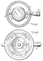
- Figure 1 is a perspective view of the small autoclave of the present invention.
- Figure 1 shows the small autoclave 10 made of metal, such as steel, aluminum, brass or various alloys.
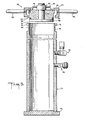
- the small autoclave 10 comprises, as shown in Fig. 5, a pressure cylinder 12 having a closed end supported by base 14 on one end thereof and open top end 16 adapted to engage closure means 18.
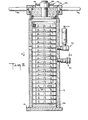
- Autoclave 10 is adapted to securely hold lens tray or lens holder 50, shown in Figures 6 and 7, made of metal or metal alloys.
- autoclave 10 is equipped with charging valve 20 through which fluids, such as steam, nitrogen or helium, may be introduced into the autoclave to attain the required pressure.
- fluids such as steam, nitrogen or helium
- safety valve 22 Spaced from said charging valve 20 is safety valve 22 to provide for release of excessive pressure and insure safety of operating personnel and equipment.
- Open top end 16 of autoclave 10 is beveled 24 and has a plurality of protruding first lugs 26 thereon, as shown in Figure 5.
- Closure means 18 comprises: compression lid 28 integral with male threaded member 30, said male threaded member 30 infixed in closure head member 32 and protruding therefrom to recieve female threaded member 34; closure head member 32 is beveled to form "O" ring retainer to accomodate an "O" ring and retain the same between it and compression lid 28; female threaded member 34 is equipped with a first pair of turn ears 36 to facilitate turning of female threaded member 34 on male threaded member 30; "O" ring 40 of an elastic material such as rubber or plastic, is held in position by compression lid 28 and "O" ring retainer 38; pressure lock ring 42 having inwardly protruding second lugs 44 thereon, said second lugs to engage said first lugs 26, located on top end 16 of the autoclave 10, upon closing of the autoclave; and a second pair of turn ears 46 mounted on pressure lock ring 42 to facilitate easy engagement of first lugs 26 with second lugs 44.
- lens tray 50 used as an integral part of autoclave 10 in bonding composite lenses, the same is designed to hold lenses aligned horizontally in a vertical array comprising:
- lens tray 50 is stacked with composite lenses to be bonded by individually disengaging from rod 54 and swinging outward therefrom each of lens support members 60 as shown in Fig. 7 and stacking lenses thereon.
- the active surfaces of the composite lenses do not contact the lens support members to avoid abrasion thereof.
- Lens retaining means 64 prevent the lenses from moving and sliding off from lens support members 60, however, they allow sufficient "play” or movement for positioning and removing the lenses.
- lens support members include: their configuration allowing easy removal of lenses therefrom by holding the lenses at their non-active surfaces; and the provision for individual mounting, opening and closing of the lens support members which allows for eacy stacking and unstacking of lenses without the necessity of sliding the lenses into position thereby risking contact and abrasion of the active surfaces thereof.
- the individual lens support means 60 are closed so as to engage u-shaped engaging means 66 with rod 54.
- Lens tray 50 is placed into autoclave 10 and closure means 18 is locked into position as follows. With a turning motion second lugs 44 are positioned between first lugs 26 thereby inserting compression lid 28, O ring 40, and O ring retainer 38 into top end 16 of autoclave 10.
- closure means 18 is turned the distance between two lugs, which is about 1/3 of a complete revolution, by using as a handle second pair of turn ears 46. This turning motion results in second lugs 44 engaging first lugs 26.
- female threaded member 34 is tightened up by turning the same clockwise, using first pair of turn ears 36.
- the autoclave After closing, the autoclave is charged with a suitable fluid, such as air, steam, nitrogen or helium via charging means 20 from an external source, placed in a heating apparatus, such as an oven, and is subjected to a pressure-temperature cycle to accomplish joining of the components of the composite lens.
- a suitable fluid such as air, steam, nitrogen or helium
- the pressure temperature conditions in the cycle should be tailor-made to the properties of the components used in the composite lens and may widely vary according to such properties. Such tailoring of the conditions, are, however, within the capabilities of those skilled in the art and the apparatus of the present invention may be used under such varying conditions.
- a typical process, tailored to a two-component laminate, illustrating the utilization of the apparatus of the present invention follows.
- a prefinished inorganic glass lens ground and polished to prescription on both active surfaces is prepositioned and prelaminated to a composite organic polyurethane wafer, which is in the form of a clear film of less than one mm thickness and placed in the autoclave for permanently bonding of glass and plastic components.
- the autoclave After charging the autoclave with a fluid, the autoclave is heated by an external heat source and the internal pressure of the autoclave is controlled by the external heat source. It has been found that a minimum pressure of about 120 psi (8 bars) is necessary for the adhesive forces to develop adequately between the film and the glass. The maximum pressure which may be applied is limited only by the equipment design and material strength. It was also found that the minimum temperature of about 200°F.
Landscapes
- Physics & Mathematics (AREA)
- Health & Medical Sciences (AREA)
- Oral & Maxillofacial Surgery (AREA)
- Thermal Sciences (AREA)
- Joining Of Glass To Other Materials (AREA)
- Lining Or Joining Of Plastics Or The Like (AREA)
Applications Claiming Priority (2)
| Application Number | Priority Date | Filing Date | Title |
|---|---|---|---|
| US06/493,546 US4547242A (en) | 1983-05-11 | 1983-05-11 | Autoclave for bonding composite lenses |
| US493546 | 1983-05-11 |
Publications (2)
| Publication Number | Publication Date |
|---|---|
| EP0127799A2 true EP0127799A2 (fr) | 1984-12-12 |
| EP0127799A3 EP0127799A3 (fr) | 1986-06-11 |
Family
ID=23960687
Family Applications (1)
| Application Number | Title | Priority Date | Filing Date |
|---|---|---|---|
| EP84105335A Withdrawn EP0127799A3 (fr) | 1983-05-11 | 1984-05-11 | Autoclave et procédé pour assembler des lentilles composites |
Country Status (2)
| Country | Link |
|---|---|
| US (1) | US4547242A (fr) |
| EP (1) | EP0127799A3 (fr) |
Families Citing this family (6)
| Publication number | Priority date | Publication date | Assignee | Title |
|---|---|---|---|---|
| US5307841A (en) * | 1992-08-10 | 1994-05-03 | Rectorseal Corporation | Test plug for waste pipe |
| GB0027272D0 (en) * | 2000-11-08 | 2000-12-27 | Advanced Biotech Ltd | Storage unit |
| US7137799B2 (en) * | 2003-07-29 | 2006-11-21 | Howard Victor Banasky | Vessel and system for curing a repair to a component made from composite materials |
| DE10335592A1 (de) * | 2003-07-31 | 2005-03-10 | Mts Maschinenbau Gmbh | Stapelsäule |
| US7452431B2 (en) * | 2004-07-30 | 2008-11-18 | Finisar Corporation | Optical product cure oven |
| CN103118774A (zh) * | 2010-07-16 | 2013-05-22 | 萨格奈铝业技术股份有限公司(Stas) | 金属浮渣隔离装置以及相关方法 |
Family Cites Families (18)
| Publication number | Priority date | Publication date | Assignee | Title |
|---|---|---|---|---|
| US1226023A (en) * | 1917-01-22 | 1917-05-15 | Walter Archie Smith | Clamp for soil-pipe test-plugs. |
| FR661190A (fr) * | 1928-01-16 | 1929-07-22 | Procédé et appareil pour la vulcanisation d'objets en caoutchouc, ébonite, etc. | |
| GB409746A (en) * | 1932-11-04 | 1934-05-04 | Harry Pitt Dean | Improvements in or relating to lids for pressure-resisting vessels |
| US2131753A (en) * | 1936-06-04 | 1938-10-04 | Rubatex Products Inc | Multiwall autoclave |
| US2105418A (en) * | 1936-11-10 | 1938-01-11 | Carl H Hoffstetter | Broiler drawer for gas ranges and the like |
| US2260710A (en) * | 1939-05-18 | 1941-10-28 | Jean F Gschwind | Autoclave and the like |
| US2405167A (en) * | 1943-09-03 | 1946-08-06 | American Cyanamid Co | Apparatus for fluid treating under controlled conditions |
| US2886067A (en) * | 1957-07-22 | 1959-05-12 | Lummus Co | Pipe testing plug |
| US3074838A (en) * | 1959-11-30 | 1963-01-22 | Harvey J Little | Evacuation ring for laminating process |
| US3150935A (en) * | 1960-12-05 | 1964-09-29 | Shampaine Ind Inc | Laboratory autoclaves |
| US3508996A (en) * | 1963-04-25 | 1970-04-28 | Chrysler Corp | Pressure vessel for laminating operations |
| US3547589A (en) * | 1967-12-14 | 1970-12-15 | Chemotronics International Inc | Shuttle type pressure vessel |
| US3660886A (en) * | 1969-02-20 | 1972-05-09 | Ginori Ceramica Ital Spa | Method of making firing setters for tiles and other ceramic articles |
| DE2409013C3 (de) * | 1974-02-25 | 1979-03-01 | Ashland Optical Corp., Long Island City, N.Y. (V.St.A.) | Mehrfachform zum Gießen optischer Kunststofflinsen |
| DE2626506C3 (de) * | 1976-06-12 | 1979-03-01 | Maschinenbau Scholz Gmbh & Co Kg, 4420 Coesfeld | Einrichtung zum Vulkanisieren von im wesentlichen ringförmigen Erzeugnissen, vorzugsweise von Keilriemen |
| US4184841A (en) * | 1978-03-01 | 1980-01-22 | Allied Insulators, Limited | Kiln furniture, particularly crank structures |
| DE2934789A1 (de) * | 1979-08-29 | 1981-03-19 | Hoechst Ag, 6000 Frankfurt | Schnellverschlussvorrichtung fuer druckbehaelter |
| SE443100B (sv) * | 1982-03-26 | 1986-02-17 | Sven Runo Vilhelm Gebelius | Sett att framstella ett koniskt rorformigt element jemte element framstellt enligt settet |
-
1983
- 1983-05-11 US US06/493,546 patent/US4547242A/en not_active Expired - Fee Related
-
1984
- 1984-05-11 EP EP84105335A patent/EP0127799A3/fr not_active Withdrawn
Also Published As
| Publication number | Publication date |
|---|---|
| US4547242A (en) | 1985-10-15 |
| EP0127799A3 (fr) | 1986-06-11 |
Similar Documents
| Publication | Publication Date | Title |
|---|---|---|
| US5778968A (en) | Method for heating or cooling wafers | |
| US4547242A (en) | Autoclave for bonding composite lenses | |
| US6177032B1 (en) | Polarized ophthalmic lenses and methods for making same | |
| KR100533475B1 (ko) | 광학 렌즈의 압축 성형 | |
| US3902693A (en) | Mold for casting lenses | |
| US20010038438A1 (en) | Formed polyethylene terephthalate polarizing film for incorporation in optical-grade plastic parts | |
| US12059768B2 (en) | Blocking piece and method for vacuum blocking a lens blank | |
| JPS62189122A (ja) | 光学装置を製造する方法 | |
| JPH0419171B2 (fr) | ||
| CN105093373B (zh) | 用于制造眼镜片的方法以及所述镜片 | |
| US4495015A (en) | Controlled wafer relaxing in making composite lenses | |
| US4883524A (en) | Invisible flat-top mold blank and method for manufacturing same | |
| US20040262187A1 (en) | Clean room transportation package for process chamber kit | |
| JPH0142900B2 (fr) | ||
| JP5616697B2 (ja) | 包装体、及び光学素子の製造方法 | |
| CN201132651Y (zh) | 一种传输外壳 | |
| US6261866B1 (en) | Method and apparatus for sealing a chip carrier and lid | |
| US20040222537A1 (en) | Method for forming a wafer for use in an optical part and an optical part incorporating such a wafer | |
| US2796313A (en) | Means and method of heat-joining glass articles | |
| JP2007186415A (ja) | 熱成形により光学部品を製造する方法および装置 | |
| TWI310011B (en) | Heat seal apparatus for lens packages | |
| US6620284B2 (en) | Even pressure welding method by using fluid pressure | |
| CN222757139U (zh) | 一种便于携带的农产品包装盒 | |
| JP2006520904A (ja) | インライン型リーク検出器 | |
| GB1485749A (en) | Method of protecting a polished glass article from tarnish during storage |
Legal Events
| Date | Code | Title | Description |
|---|---|---|---|
| PUAI | Public reference made under article 153(3) epc to a published international application that has entered the european phase |
Free format text: ORIGINAL CODE: 0009012 |
|
| AK | Designated contracting states |
Designated state(s): AT BE CH DE FR GB IT LI LU NL SE |
|
| PUAL | Search report despatched |
Free format text: ORIGINAL CODE: 0009013 |
|
| AK | Designated contracting states |
Kind code of ref document: A3 Designated state(s): AT BE CH DE FR GB IT LI LU NL SE |
|
| 17P | Request for examination filed |
Effective date: 19860808 |
|
| 17Q | First examination report despatched |
Effective date: 19870629 |
|
| STAA | Information on the status of an ep patent application or granted ep patent |
Free format text: STATUS: THE APPLICATION IS DEEMED TO BE WITHDRAWN |
|
| 18D | Application deemed to be withdrawn |
Effective date: 19881010 |
|
| RIN1 | Information on inventor provided before grant (corrected) |
Inventor name: GRIFFITH, JOHN M. Inventor name: HILL, PHILLIP D. Inventor name: TUSINSKI, JOSEPH |