EP0127828A2 - Appareil pour l'apport de mousse en continu sur une surface devant en être enduite - Google Patents
Appareil pour l'apport de mousse en continu sur une surface devant en être enduite Download PDFInfo
- Publication number
- EP0127828A2 EP0127828A2 EP84105736A EP84105736A EP0127828A2 EP 0127828 A2 EP0127828 A2 EP 0127828A2 EP 84105736 A EP84105736 A EP 84105736A EP 84105736 A EP84105736 A EP 84105736A EP 0127828 A2 EP0127828 A2 EP 0127828A2
- Authority
- EP
- European Patent Office
- Prior art keywords
- container
- foaming
- elements
- opening
- foam
- Prior art date
- Legal status (The legal status is an assumption and is not a legal conclusion. Google has not performed a legal analysis and makes no representation as to the accuracy of the status listed.)
- Ceased
Links
Images



Classifications
-
- D—TEXTILES; PAPER
- D06—TREATMENT OF TEXTILES OR THE LIKE; LAUNDERING; FLEXIBLE MATERIALS NOT OTHERWISE PROVIDED FOR
- D06B—TREATING TEXTILE MATERIALS USING LIQUIDS, GASES OR VAPOURS
- D06B1/00—Applying liquids, gases or vapours onto textile materials to effect treatment, e.g. washing, dyeing, bleaching, sizing or impregnating
- D06B1/08—Applying liquids, gases or vapours onto textile materials to effect treatment, e.g. washing, dyeing, bleaching, sizing or impregnating from outlets being in, or almost in, contact with the textile material
-
- D—TEXTILES; PAPER
- D06—TREATMENT OF TEXTILES OR THE LIKE; LAUNDERING; FLEXIBLE MATERIALS NOT OTHERWISE PROVIDED FOR
- D06B—TREATING TEXTILE MATERIALS USING LIQUIDS, GASES OR VAPOURS
- D06B19/00—Treatment of textile materials by liquids, gases or vapours, not provided for in groups D06B1/00 - D06B17/00
- D06B19/0088—Treatment of textile materials by liquids, gases or vapours, not provided for in groups D06B1/00 - D06B17/00 using a short bath ratio liquor
- D06B19/0094—Treatment of textile materials by liquids, gases or vapours, not provided for in groups D06B1/00 - D06B17/00 using a short bath ratio liquor as a foam
Definitions
- the invention relates to a device for applying foams continuously produced from flowable, foamable media to a flat structure to be coated therewith, e.g. a web-shaped textile material, with a finished foam-receiving container arranged directly above the wide structure, which has a slot-like opening on the underside facing the structure with the desired coating width corresponding slot length, the container being designed as a foaming device and in the container supply lines for a mixture consisting of foamable medium and propellant gas open.
- Devices of the type described above are used in particular in textile finishing, e.g. for coating carpets or for dyeing sheet-like textile material. Foam coating is also used in the paper industry, e.g. in wallpaper manufacturing.
- the always freshly produced foam is made using a Coating device applied to which the foam produced in a separate foaming device is fed via a line, for example a hose or pipe.
- the foaming device requires complicated control so that there are no deviations in the quality and quantity of the foam produced continuously.
- the operation of the coating device is to be controlled at the same time, difficulties being able to arise in particular because parameters responsible for the operation of the foaming device are not without influence on corresponding parameters of the coating device, and vice versa.
- the unavoidable delay in readjustment also has a particularly disadvantageous effect.
- deviations from the desired foam quality or amount of foam can only be determined by an observer directly in the coating area of the coating device.
- the foaming device Before necessary adjustments are made to the foaming device, the foaming device has already produced a not inconsiderable amount of defective foam and the container of the Coating device supplied and the corresponding effects of the readjustments can only be observed with a time delay in the coating area of the coating device when the container flow has ended.
- Attempts have already been made to solve this problem with a remote control for the foaming device that can be operated from the location of the coating device.
- this measure requires considerable design effort and does not avoid the delay mentioned, but only speeds up the readjustment process itself, since the observing operator no longer has to leave the observation site for readjustment of the foaming device.
- a device is described in US Pat. No. 4,297,860 in which the foaming device forms a structural unit with the coating device; the foaming device is "integrated" into the coating device, so to speak.
- the separate installation of a foaming device is unnecessary, which means that the design effort for the device according to the invention is less.
- the exit opening, from which finished foam leaves the foaming device, is practically directly at the location of the coating. Deviations in the amount of foam observed during the operation of the device can be readjusted without significant delays.
- Supply lines for a mixture consisting of foamable medium and propellant gas open into the container.
- the invention has for its object to improve the known device with regard to its operation of foaming and application.
- Foaming devices with mechanically working foaming elements are advantageously suitable for the continuous production of foams, even from materials that are more difficult to foam.
- Propellant gas eg air
- the amount of both the coating products and the air can be controlled.
- the mechanically wrapped The amount of air is decisive for the degree of foaming and thus for the concentration and viscosity of the foam, and consequently the quality of the continuously produced foam also depends in particular on the mechanical operation of the foaming elements.
- Containers and foaming elements can be designed with any shape that is expediently matched to one another.
- the container has a cylindrical shape and has a centrally arranged positively driven shaft, on which the foaming elements are arranged.
- the cylindrical shape of the container is easy to manufacture and has the advantage that it can easily withstand the operating pressure of a few bar that arises in the device.
- the cylindrical shape also allows a simple and constructive arrangement of the shaft.
- the wave can e.g. are prefabricated by equipping them with foaming elements and the installation of such a prefabricated part in the cylindrical container is then relatively easy to assemble.
- each foaming element is a perforated disk rotating with the shaft with any hole pattern.
- Read the disks can be attached to the shaft in any number one after the other. All discs attached to a shaft can have the same hole pattern. However, it is also possible to vary the hole patterns within a disc or to arrange discs with different hole patterns on a shaft.
- the disks are easy to manufacture components, for example made of plastic.
- the diameter of the disks preferably corresponds approximately to the inner diameter of the cylindrical container, which ensures that the medium to be foamed, when flowing in the longitudinal direction of the container, must pass through the holes in the disks.
- each disk is curved in a bowl shape.
- the bowl-shaped, curved disks are preferably arranged on the shaft in such a way that their open side formed by the curvature faces the direction of flow of the mixture of foamable medium and propellant gas supplied.
- the bowl-shaped curvature has the advantage that the surface of each pane in contact with the medium to be foamed is larger than that of a flat pane.
- a rotating bowl-shaped disc brings about an advantageous mixing and swirling, whereas with a flat disc there is a risk that it will only cut through the medium to be foamed.
- each disc is associated with a swirl element carried by the shaft.
- a swirling element can be designed, for example, in the manner of a paddle wheel and, for example, have the shape of a propeller. Swirling elements of this type can be fastened on the shaft, in which case they rotate with them or work at a different speed with respect to the rotational movement of the perforated disks. It is also possible to arrange such swirling elements stationary.
- each feed line is an angled piece branching off from a pipe located outside the cylindrical container, which preferably penetrates the container wall perpendicularly in the area of a respectively assigned disk and within of the container has a bend directed into the bowl-shaped curvature of the disk with a nozzle-like outflow opening.
- the mixture of medium and propellant gas fed into the pipeline is thus divided into partial flows by the feed lines, each partial flow entering the cylindrical container in the area of an assigned disk.
- the deflection effect of the flow causes premixing and pre-foaming by converting a large part of the static to dynamic pressure of the liquid-gas mixture.
- the nozzle-like constricted outflow opening advantageously produces an outflow with ho hem dynamic pressure potential.
- the pipeline upstream of the individual feed lines designed as elbows is designed as a premixing chamber.
- Statically operating foaming elements are arranged in the premixing chamber.
- Such statically working foaming elements can e.g. known fillers, baffles or the like.
- the foam produced in the cylindrical container emerges from the container through the slit-like opening arranged on its underside, which has a closure element that works as a function of the system pressure.
- the closure member ensures complete sealing of the slot-like opening when the device is at a standstill if no propellant gas or liquid is introduced.
- the closure member only opens when a predetermined pressure is reached during the production of foam.
- Lip elements arranged against each other and pressing against each other are provided as closure elements on each opening edge of the slot opening. This design of a closure member has the advantage that a uniform seal over the entire length of the slot opening is possible with simple constructional means.
- the lip elements are preferably made of an elastic material, wherein the opening pressure can be specified via the shape and rigidity of the lip elements. When the device is at a standstill, the lip elements press against each other due to their inherent elasticity and only when they are reached The lip elements are pressed apart by a pressure of the foam at a predetermined opening pressure.
- At least one of the lip elements is designed as a flap articulated on the opening edge, which is operatively connected to an actuator.
- This training allows e.g. to manufacture the flap, which is operatively connected to an actuator, from sheet metal or another wear-resistant material, against which an associated lip element made of elastic material rests.
- flaps made of metallic material which are lip-shaped, are used.
- a spring mechanism e.g. a spring mechanism
- the predetermined opening pressure can advantageously be set very easily.
- pressure-controlled control systems are also possible.
- an elastic lip element or a hinged flap replacing a lip element are acted upon and held tight by pressure-controlled means.
- the above-described device is arranged over the pass-through path of a sheet-like structure to be coated, it can already be used with the slot-like opening Apply a coating when the foam comes out.
- the most precise alignment possible is required over the web-like material to be coated.
- the precise setting and adjustment work required for this can be facilitated by arranging a channel element leading to the coating area at the slot-like opening.
- This measure has the advantage that it is no longer necessary to move the entire device for setting and adjustment, but only the channel element.
- the channel element can be a structurally simple component in that it is a flat tube made of flexible material, at the free end of which a box-shaped outlet part is arranged.
- This design also has the advantage that the channel element can fulfill the task of a shape-changing slot nozzle due to the predetermined shape or elastic properties of the materials used for the flat hose.
- control elements for the foam flow are assigned to the flat tube.
- a regulating element can be, for example, a squeeze element that can be pressed against the hose from the outside and through which the free cross section of the flat hose can be narrowed.
- the predetermined amount of foam that is desired for coating on the web-shaped material is always supplied to the outlet part of the channel element.
- the box-shaped outlet part can, for example, consist of relatively rigid plates, which can be made of stainless steel or plastic. This allows the arrangement of elements with which an adaptation of the foam outlet to one predetermined order width is possible, for example, in that the length of the free outlet walls of the outlet part are designed as adjustable slides.
- a pair of lips made of elastic material is arranged at the free outlet of the outlet part. These lips generally perform the function of a squeegee known per se, depending on the area of application of the device, the lips either sealing against the flat material to be coated or specifying the amount of foam applied.
- All components of the device are advantageously arranged in a closed housing, the housing being movably guided in the vertical direction by means of an actuating device on a support frame. This makes it possible to carry out the layer thickness of the foam to be applied to a material to be coated directly by adjusting the height of the housing.
- the device is characterized by the fact that it has connection elements for coupling with devices which are placed adjacent to one another in order to enlarge the working width.
- This makes it possible to place and couple several devices in a very simple manner according to the "modular principle". to e.g. to be able to coat even very wide flat structures in one pass, in particular when the width of the structure to be coated would lead to dimensions of the device which are hardly practical.
- the device according to the invention can be combined with any order tables known per se, which for Serve guidance of the web-like structure to be coated.
- FIG. 1 shows an overall view of the device for coating a flat structure, here a web 1 made of textile material.
- a cylindrical container 2 Extending across the width of the web 1 is a cylindrical container 2, on the underside of which the web 5 faces a slot-like opening 3.
- the web 1 will be in the direction of the arrow to the device moves.
- a driven shaft 4 In the cylindrical container there is a driven shaft 4, on which there are foaming elements which are regularly distributed over the length of the shaft and which are designed here as perforated disks 5.
- the supply line 7 for the compressed air opens outside the cylindrical container 2 into the supply line 6, so that mixing already takes place there.
- the mixture leading end of the feed line 6 then opens into a pipe which extends along the container but is still outside the container, which is designed here as a premixing chamber 8 and is equipped in a manner known per se with statically operating foaming elements.
- Static foaming elements of this type can be, for example, fillers known per se, such as glass balls, ceramic tubes, various deflection plates, propeller elements or the like.
- feed lines branch off from the premixing chamber 8, which here are designed as angle pieces 9 extending from the premixing chamber, which penetrate the cylinder wall perpendicularly in the area of a respectively assigned disk 5 and within the cylinder a bend 10 directed towards the assigned disk 5 with a nozzle-like constriction Have outflow opening 11.
- a channel element leading to the coating area is connected, which here is a meandering flexible flat hose 12, at the free end of which a rigid box-shaped outlet part 13 is arranged.
- 14 and 15 are rod-shaped brackets, over which the flat tube is guided, and thereby receives its meandering shape.
- a pair of lips 16 made of elastic material is used to perform the function of a doctor blade.
- FIG. 2 shows a schematic side view of the device according to FIG. 1 in cross section.
- the same components are labeled with the same reference numbers.
- the closure member consists in this embodiment of lip elements, one of which is arranged at each opening edge of the slot opening 3.
- Each lip element is a flap 17 articulated on the opening edge, at least one of the flaps being operatively connected to an actuator, not shown, for example a spring mechanism.
- the meandering shape of the channel element designed as a flat tube 12 is clearly visible, which, due to the flexible material used, fulfills the function of a variable slot nozzle.
- the Flat hose assigned a control element, which is designed here as a squeeze member 18 pressing against the hose from the outside.
- the squeeze member can be designed, for example, as a bar.
- the box-shaped outlet part 13 e.g. made of stainless steel sheets, connected.
- walls which limit the length of the free outlet of the outlet part 13 are designed as adjustable slides 19 which can be moved from the outside via an actuating element 20.
- Fig. 3 a part of the container 2 of the device g e according to Fig. 1 and 2 is shown in longitudinal section and on an enlarged scale.
- the shaft 4 carries foaming elements which rotate with the shaft and are designed here as perforated disks 5 and 5a.
- the disks are bowl-shaped and can e.g. be made of plastic material.
- Each disc has a diameter which corresponds to the inside diameter of the container 2.
- the outer circumference of the disks can have scrapers that graze along the inner wall of the container.
- the disks 5 and 5a differ in the arrangement of such wipers 36 and 36a.
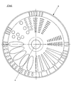
- FIG. 4 shows a schematic top view of a perforated disk 5 which is fastened on the shaft 4. Due to the geometric axes, the image of the perforated disc 5 is divided into four quadrants, each quadrant showing a possibility of executing a different hole pattern.
- the housing carries at the end a drive element for the shaft 4, which here consists of two angular gears 25 and 26, an electric motor 30 being flanged to the angular gear 26. Furthermore, the housing has externally attached holding rails 27, which allow the entire device to be guided so that it can be adjusted vertically within a machine frame (not shown), as a result of which the thickness of the foam layer applied to the web 1 to be coated can be changed and adjusted.
- FIG. 6 shows a schematic exemplary embodiment in which three devices are placed side by side.
- the shafts 4 of the devices can be connected to one another by couplings arranged in the regions 28 and 29.
- the This arrangement enables a wide web 1 to be coated with a foam layer.
- the outer end faces of the two outer devices each have an electric motor 30.
Landscapes
- Engineering & Computer Science (AREA)
- Textile Engineering (AREA)
- Coating Apparatus (AREA)
- Application Of Or Painting With Fluid Materials (AREA)
- Nozzles (AREA)
Applications Claiming Priority (2)
| Application Number | Priority Date | Filing Date | Title |
|---|---|---|---|
| DE3318711A DE3318711C2 (de) | 1983-05-21 | 1983-05-21 | Vorrichtung zum kontinuierlichen Herstellen und Auftragen von Schaum auf ein zu beschichtendes flächiges Gebilde |
| DE3318711 | 1983-05-21 |
Publications (2)
| Publication Number | Publication Date |
|---|---|
| EP0127828A2 true EP0127828A2 (fr) | 1984-12-12 |
| EP0127828A3 EP0127828A3 (fr) | 1986-03-12 |
Family
ID=6199682
Family Applications (1)
| Application Number | Title | Priority Date | Filing Date |
|---|---|---|---|
| EP84105736A Ceased EP0127828A3 (fr) | 1983-05-21 | 1984-05-19 | Appareil pour l'apport de mousse en continu sur une surface devant en être enduite |
Country Status (5)
| Country | Link |
|---|---|
| US (1) | US4557218A (fr) |
| EP (1) | EP0127828A3 (fr) |
| JP (1) | JPS6034763A (fr) |
| DE (1) | DE3318711C2 (fr) |
| DK (1) | DK245784A (fr) |
Cited By (1)
| Publication number | Priority date | Publication date | Assignee | Title |
|---|---|---|---|---|
| FR2586591A1 (fr) * | 1985-08-27 | 1987-03-06 | Armstrong World Ind Inc | Appareil d'homogeneisation, appareil de revetement en rideau le comportant et procede pour l'utilisation de cet appareil de revetement. |
Families Citing this family (20)
| Publication number | Priority date | Publication date | Assignee | Title |
|---|---|---|---|---|
| US7338980B2 (en) * | 1995-12-01 | 2008-03-04 | Sunstar Giken Kabushiki Kaisha | Method and apparatus for mixing a high-viscosity material into a gas |
| US6395088B1 (en) * | 1999-06-30 | 2002-05-28 | Gaston Systems, Inc. | Apparatus for applying foamed coating material to a traveling textile substrate |
| US6503412B1 (en) | 2000-08-24 | 2003-01-07 | Kimberly-Clark Worldwide, Inc. | Softening composition |
| US6607783B1 (en) | 2000-08-24 | 2003-08-19 | Kimberly-Clark Worldwide, Inc. | Method of applying a foam composition onto a tissue and tissue products formed therefrom |
| DE60136742D1 (de) | 2000-11-08 | 2009-01-08 | Kimberly Clark Co | Schaumbehandlung von tissueprodukten |
| DE10106371A1 (de) * | 2001-02-12 | 2002-08-14 | Ludwig Pilsl | Vorrichtung für den Austausch von Wärme |
| US6805965B2 (en) | 2001-12-21 | 2004-10-19 | Kimberly-Clark Worldwide, Inc. | Method for the application of hydrophobic chemicals to tissue webs |
| US6835418B2 (en) | 2002-05-31 | 2004-12-28 | Kimberly-Clark Worldwide, Inc. | Use of gaseous streams to aid in application of foam to tissue products |
| US6797116B2 (en) | 2002-05-31 | 2004-09-28 | Kimberly-Clark Worldwide, Inc. | Method of applying a foam composition to a tissue product |
| US6797319B2 (en) | 2002-05-31 | 2004-09-28 | Kimberly-Clark Worldwide, Inc. | Application of foam to tissue products using a liquid permeable partition |
| US6814806B2 (en) | 2002-07-25 | 2004-11-09 | Gaston Systems Inc. | Controlled flow applicator |
| US20040055534A1 (en) * | 2002-09-19 | 2004-03-25 | Gaston Systems, Inc. | Fluid applicator for permeable substrates |
| US6977026B2 (en) | 2002-10-16 | 2005-12-20 | Kimberly-Clark Worldwide, Inc. | Method for applying softening compositions to a tissue product |
| US6761800B2 (en) | 2002-10-28 | 2004-07-13 | Kimberly-Clark Worldwide, Inc. | Process for applying a liquid additive to both sides of a tissue web |
| US6964725B2 (en) | 2002-11-06 | 2005-11-15 | Kimberly-Clark Worldwide, Inc. | Soft tissue products containing selectively treated fibers |
| US7029756B2 (en) | 2002-11-06 | 2006-04-18 | Kimberly-Clark Worldwide, Inc. | Soft tissue hydrophilic tissue products containing polysiloxane and having unique absorbent properties |
| US6949168B2 (en) | 2002-11-27 | 2005-09-27 | Kimberly-Clark Worldwide, Inc. | Soft paper product including beneficial agents |
| US7396593B2 (en) | 2003-05-19 | 2008-07-08 | Kimberly-Clark Worldwide, Inc. | Single ply tissue products surface treated with a softening agent |
| US7431771B2 (en) | 2004-11-12 | 2008-10-07 | Gaston Systems, Inc. | Apparatus and method for applying a foamed composition to a dimensionally unstable traveling substrate |
| CN205393066U (zh) * | 2016-03-07 | 2016-07-27 | 成都京东方光电科技有限公司 | 喷淋设备 |
Family Cites Families (7)
| Publication number | Priority date | Publication date | Assignee | Title |
|---|---|---|---|---|
| US3377139A (en) * | 1963-06-21 | 1968-04-09 | Allied Chem | Apparatus for preparing low density urea-formaldehyde foams |
| ES448040A1 (es) * | 1975-05-24 | 1977-07-01 | Hoechst Ag | Dispositivo para la aplicacion uniforme de banos liquidos detratamiento en forma de espuma sobre estructuras textiles planas. |
| US4297860A (en) * | 1980-07-23 | 1981-11-03 | West Point Pepperell, Inc. | Device for applying foam to textiles |
| US4405491A (en) * | 1980-10-02 | 1983-09-20 | Sando Iron Works Co., Ltd. | Apparatus for forming foam |
| DE3044409C2 (de) * | 1980-11-26 | 1983-04-28 | Mathias 4815 Schloss Holte Mitter | Vorrichtung zum kontinuierlichen Auftragen einer Flotte in Form von Schaum auf eine vorzugsweise textile Warenbahn |
| DE3230492A1 (de) * | 1982-08-17 | 1984-02-23 | Mathias 4815 Schloss Holte Mitter | Rotierend angetriebener schaumgenerator |
| DE3231930C2 (de) * | 1982-08-27 | 1984-12-13 | Mathias 4815 Schloss Holte Mitter | Vorrichtung zur Herstellung verschäumter Flotten zum Auftrag auf eine textile o.dgl faserige Warenbahn |
-
1983
- 1983-05-21 DE DE3318711A patent/DE3318711C2/de not_active Expired
-
1984
- 1984-05-17 DK DK245784A patent/DK245784A/da not_active Application Discontinuation
- 1984-05-19 EP EP84105736A patent/EP0127828A3/fr not_active Ceased
- 1984-05-21 JP JP59100716A patent/JPS6034763A/ja active Pending
- 1984-05-21 US US06/612,353 patent/US4557218A/en not_active Expired - Fee Related
Cited By (1)
| Publication number | Priority date | Publication date | Assignee | Title |
|---|---|---|---|---|
| FR2586591A1 (fr) * | 1985-08-27 | 1987-03-06 | Armstrong World Ind Inc | Appareil d'homogeneisation, appareil de revetement en rideau le comportant et procede pour l'utilisation de cet appareil de revetement. |
Also Published As
| Publication number | Publication date |
|---|---|
| DK245784A (da) | 1984-11-22 |
| JPS6034763A (ja) | 1985-02-22 |
| DE3318711C2 (de) | 1986-01-23 |
| EP0127828A3 (fr) | 1986-03-12 |
| DE3318711A1 (de) | 1984-11-29 |
| DK245784D0 (da) | 1984-05-17 |
| US4557218A (en) | 1985-12-10 |
Similar Documents
| Publication | Publication Date | Title |
|---|---|---|
| DE3318711A1 (de) | Vorrichtung zum kontinuierlichen auftragen von schaum auf ein damit zu beschichtendes flaechiges gebilde | |
| DE3324106C2 (fr) | ||
| AT392602B (de) | Streicheinrichtung zur beschichtung laufender warenbahnen | |
| DE3034804A1 (de) | Vorrichtung zum auftragen eines mediums auf eine siebdruckschablone | |
| DE3516978A1 (de) | Beschichtungsvorrichtung zum beschichten einer bewegten bahn aus papier oder pappe | |
| EP3213824A1 (fr) | Dispositif et procede d'application de colle sur un substrat | |
| EP0235166B1 (fr) | Dispositif pour l'application d'un liquide sur un materiau en bande | |
| DE3623402C2 (fr) | ||
| DE19651739A1 (de) | Auftragwerk zum direkten oder indirekten Auftragen eines flüssigen oder pastösen Streichmediums auf eine laufende Materialbahn, insbesondere aus Papier oder Karton | |
| DE3034807C2 (de) | Vorrichtung zum Auftragen von Medien auf Warenbahnen | |
| EP0781885A1 (fr) | Appareil d'enduction pour déposer directement ou indirectement un matériau fluide ou pâteux sur une bande en mouvement | |
| EP0677613A2 (fr) | Dispositif pour déposer au moins un matériau fluide sur une bande en mouvement | |
| EP2277630A2 (fr) | Dispositif de revêtement d'une bande traversante | |
| DE3048133C2 (de) | Beschichtungsvorrichtung mit Luftdüsenanordnung | |
| EP0757129B1 (fr) | Système d'application pour un appareil de revêtement d'une feuille de papier ou carton | |
| DE2611625C3 (fr) | ||
| EP0056067B1 (fr) | Dispositif pour appliquer une couche mince d'une substance d'enduction sur une bande de matériau en mouvement | |
| DE8315154U1 (de) | Vorrichtung zum kontinuierlichen Auftragen von Schaum auf ein damit zu beschichtendes flächiges Gebilde | |
| EP2055832A2 (fr) | Dispositif destiné au réglage de la largeur de revêtement d'un revêtement devant être appliqué à l'aide d'une machine de couchage de rideau | |
| EP0717932A2 (fr) | Installation pour exécuter un procédé de dragéification et/ou glaçage | |
| EP0783053B1 (fr) | Dispositif d'enduction pour déposer directement ou indirectement un matériau fluide ou pâteux sur une bande en mouvement | |
| DE19516422A1 (de) | Druckmaschine mit einer für einen Zylinder vorgesehenen Reinigungseinrichtung | |
| DE19532920A1 (de) | Auftragswerk zum direkten oder indirekten Auftragen eines flüssigen oder pastösen Mediums auf eine laufende Materialbahn | |
| DE29610773U1 (de) | Freistrahldüsen-Auftragseinrichtung | |
| DE19604934A1 (de) | Auftragsystem für eine Vorrichtung zum Beschichten einer Papier- oder Kartonbahn |
Legal Events
| Date | Code | Title | Description |
|---|---|---|---|
| PUAI | Public reference made under article 153(3) epc to a published international application that has entered the european phase |
Free format text: ORIGINAL CODE: 0009012 |
|
| AK | Designated contracting states |
Designated state(s): AT BE CH DE FR GB IT LI LU NL SE |
|
| PUAL | Search report despatched |
Free format text: ORIGINAL CODE: 0009013 |
|
| AK | Designated contracting states |
Kind code of ref document: A3 Designated state(s): AT BE CH DE FR GB IT LI LU NL SE |
|
| 17P | Request for examination filed |
Effective date: 19860520 |
|
| 17Q | First examination report despatched |
Effective date: 19871006 |
|
| STAA | Information on the status of an ep patent application or granted ep patent |
Free format text: STATUS: THE APPLICATION HAS BEEN REFUSED |
|
| 18R | Application refused |
Effective date: 19880908 |
|
| RIN1 | Information on inventor provided before grant (corrected) |
Inventor name: SIEVERS, ERICH |