EP0127983A2 - Abtasten der Elektronenstrahlen in einem rechnergestützten Abtast-Tomographen - Google Patents
Abtasten der Elektronenstrahlen in einem rechnergestützten Abtast-Tomographen Download PDFInfo
- Publication number
- EP0127983A2 EP0127983A2 EP84303494A EP84303494A EP0127983A2 EP 0127983 A2 EP0127983 A2 EP 0127983A2 EP 84303494 A EP84303494 A EP 84303494A EP 84303494 A EP84303494 A EP 84303494A EP 0127983 A2 EP0127983 A2 EP 0127983A2
- Authority
- EP
- European Patent Office
- Prior art keywords
- target
- electron beam
- plane
- location
- spot
- Prior art date
- Legal status (The legal status is an assumption and is not a legal conclusion. Google has not performed a legal analysis and makes no representation as to the accuracy of the status listed.)
- Withdrawn
Links
Images


Classifications
-
- A—HUMAN NECESSITIES
- A61—MEDICAL OR VETERINARY SCIENCE; HYGIENE
- A61B—DIAGNOSIS; SURGERY; IDENTIFICATION
- A61B6/00—Apparatus or devices for radiation diagnosis; Apparatus or devices for radiation diagnosis combined with radiation therapy equipment
- A61B6/02—Arrangements for diagnosis sequentially in different planes; Stereoscopic radiation diagnosis
- A61B6/03—Computed tomography [CT]
- A61B6/032—Transmission computed tomography [CT]
-
- H—ELECTRICITY
- H01—ELECTRIC ELEMENTS
- H01J—ELECTRIC DISCHARGE TUBES OR DISCHARGE LAMPS
- H01J35/00—X-ray tubes
- H01J35/02—Details
- H01J35/14—Arrangements for concentrating, focusing, or directing the cathode ray
- H01J35/153—Spot position control
-
- A—HUMAN NECESSITIES
- A61—MEDICAL OR VETERINARY SCIENCE; HYGIENE
- A61B—DIAGNOSIS; SURGERY; IDENTIFICATION
- A61B6/00—Apparatus or devices for radiation diagnosis; Apparatus or devices for radiation diagnosis combined with radiation therapy equipment
- A61B6/40—Arrangements for generating radiation specially adapted for radiation diagnosis
- A61B6/4021—Arrangements for generating radiation specially adapted for radiation diagnosis involving movement of the focal spot
- A61B6/4028—Arrangements for generating radiation specially adapted for radiation diagnosis involving movement of the focal spot resulting in acquisition of views from substantially different positions, e.g. EBCT
-
- H—ELECTRICITY
- H01—ELECTRIC ELEMENTS
- H01J—ELECTRIC DISCHARGE TUBES OR DISCHARGE LAMPS
- H01J35/00—X-ray tubes
Definitions
- the present invention relates generally to a technique for controlling a scanning electron beam which produces X-rays in a computed tomography X-ray transmission scanner and more particularly to the use of differential focal strength beam optics to improve overall resolution of the scanner.
- the bend plane of the electron beam is the plane containing the axes of the incident and deflected beams and the scanner axis.
- the bend plane is also referred to as the radial plane of the scanner.
- the transverse plane of the electron beam is perpendicular to the bend plane and contains the axis of the deflected beam.
- the transverse plane is also referred to as the scan plane.
- the position of these planes changes continuously as the deflected electron beam rotates in the scan tube.
- the radial direction is a direction in the radial plane perpendicular to the deflected beam axis.
- the azimuthal direction is perpendicular to the radial direction and to the scanner axis.
- the axial direction is parallel to the scanner axis.
- the solenoid referred to above serves to focus the beam to a small spot on the target which results in the production of an X-ray beam having an effective focal spot size which depends on the size of the electron beam spot.
- the self forces of the beam are dominated by its space charge, i.e. the electrons mutually repel each other. This repulsion limits the minimum beam spot size (and therefore the effective focal spot size of the X-ray beam), which in the case of unit beam optical magnification, and cylindrical symmetry with respect to the beam axis is equal to the size of the initial electron beam waist at the electron gun.
- the focusing properties of the dipole are not cylindrically symmetric. Generally the dipole will have a greater focal strength in the transverse plane than in the bend plane. This causes the principal points of the solenoid/dipole combination to be closer to the target in the transverse plane than in the bend plane. Consequently, for purely beam optical reasons (i.e. for an electron beam with negligible space charge), the azimuthal (transverse) electron beam spot size is less than the radial (bend plane) beam spot size.
- the desirable focusing feature just mentioned relies on the relative displacement of the principal points in two planes.
- the preferred embodiment of the present invention which is directed to the use of a differential focal strength beam optic arrangement and which does not depend on a displacement of the principal points in the two planes.
- the effect can be illustrated using a simple thin lens approximation. Differential focal strength under this condition is of no advantage beam optically, i.e. for very low current beams with negligible space charge.
- An essential component of the scanner when used in this mode is a set of magnetic quadrupole coils which are installed inside the dipole magnets. These coils are used to optimize the difference in focal strengths of the composite magnetic lens (solenoid, dipole, quadrupole). Also, since the dipole field is rotating, the quadrupole currents must be scanned in synchronism with the dipole currents but at twice the frequency.
- a scanning electron beam computed tomography scanner which comprises means defining a vacuum chamber, means for producing a space-charge limited electron beam at one location in the chamber and for directing the beam to a second location therein, and an elongated target (also located within the chamber) of the type which produces X-rays as a result of the impingement thereon by the electron beam.
- the scanner also includes an arrangement for causing the electron beam to scan along the length of the target so as to impinge the latter at all points along its length so as to cause X-rays to be produced by and emanate from the target.
- this arrangement includes means for causing the electron beam to converge less in one plane than in an orthogonal plane, thus producing a cross-section of the beam at its point of impingement with the target generally elliptical in configuration and fixed in size at all points along the length of the target.
- the means for producing the differential convergence of the electron beam and for maintaining the beam's cross-section elliptical in configuration and fixed in size includes means for focusing the beam to a spot on the target, the focusing means specifically displaying a greater focal strength in the scan plane of the beam, at any instant along its scan path, than the focal strength in the radial plane at that instant. This is accomplished specifically by means of an assembly of dipole magnets containing a set of magnetic quadrupole coils.
- Figure 1 illustrates a scanning electron beam computed tomography scanner designed in accordance with the present invention and generally indicated by the reference numeral 10.
- scanner 10 may be identical to the one described in previously recited Boyd et al patent 4,352,021 and/or the scanner disclosed in applicant's own pending application Serial No. 434,252, filed October 14, 1982 (hereinafter referred to as the Rand application).
- the scanner includes means generally indicated at 12 for defining one section 14 of a vacuum chamber 16, means generally indicated at 18 for defining a second section 20 of the same chamber, and a vacuum pump 21 acting on the chamber.
- Means including an electron gun 22 and its own vacuum pump 21 located at the rearwardmost end of chamber 16 serves to produce a space-charge limited electron beam 24 which is directed horizontally in a continuously expanding fashion through chamber section 14 to the forwardmost end of the latter where it is acted upon in the manner to be discussed hereinafter.
- the cross-section of electron beam 24 between electron gun 22 and the forwardmost end of chamber section 14 is circular in configuration.
- means 18 defining chamber section 20 is configured to define a somewhat cone-shaped chamber section, at least to the extent that it tapers downward and outward from chamber section 14.
- scanner 10 includes a set of targets of the type which produce X-rays 28 (see Figure lA) as a result of the impingement thereon by electron beam 24.
- a typical target 26 is generally arcuate in form and extends around the inside of chamber section 20 at its forwardmost end.
- the targets form a series of stepped surfaces 30 which extend the entire length of the targets and which face the rearwardmost end of chamber section 20 in order to intercept and, as a result, be impinged by electron beam 24 in order to produce a resultant X-ray beam 28.
- the way in which electron beam 24 is directed onto target surfaces 30 forms part of the present invention and will be discussed hereinafter. For the moment, it suffices to say that surfaces 30 are angled relative to the incoming electron beam to reduce the axial width of the effective focal spot of the resultant X-ray beam.
- the X-ray beam 28 is directed upward through a patient (not shown) to one of a number of detectors 32. Overall operation of the scanner is controlled by computer processing means partially indicated at 34.
- scanner 10 may include other components (not disclosed herein) which do not form part of the present invention but which are necessary or desirable to operation of the overall scanner.
- scanner 10 includes a solenoid coil 36 and an assembly of dipole coils 38, the latter containing a set of magnetic quadrupole coils 40. While these three components, that is, the solenoid coil, assembly of dipole coils and the set of quadrupole coils, are individually known in the art, they are combined in accordance with the present invention to provide an overall arrangement 42 at the forwardmost end of chamber section 16 and the rearwardmost end of chamber section 20 for causing beam 24 to scan along the length of typical target 26 so as to impinge one of the stepped surfaces 30 at all points along its length in order to cause X-rays 28 to be produced by and emanated from the target.
- this arrangement of components maintains the convergence of the electron beam 24 greater in the scan plane than in the radial plane and thus the cross-section of electron beam 24 at its point of impingement with the target is generally elliptical in configuration (rather than circular) and fixed in size at all points along the length of the target. Moreover, the orientation of the electron beam's cross-sectional configuration at its impingement point is fixed relative to the scan path of the beam. Specifically, in the embodiment illustrated, the major axis of the elliptical beam at its point of impingement is always normal to its scan path.
- quadrupole coils 40 in combination with the dipole coils to focus the electron beam to a spot on the target utilizing differential focal strength optics.
- This can be used to reduce the azimuthal size of the spot on the X-ray target over and above what is otherwise possible with a circular beam spot when the beam is space-charge limited as discussed previously, and thereby improve the overall resolution of scanner 10.
- FIG. 2A electron beam 24 is shown diagrammatically in its scanning mode relative to arcuate target 26.
- the arcuate scan path of the electron beam is indicated at 44 and corresponds to one arcuate length of the target.
- This scan path at any given point thereon is defined by the intersection of perpendicular A (azimuthal) and R (radial) axes, as best illustrated in Figure 2B.
- the azimuthal axis is in the direction of movement of the beam and the radial axis is perpendicular thereto.
- Overall arrangement 42 focuses electron beam 24 to a spot 46 on the surface 30 of target 26, as best shown in Figure 2B.
- this spot is generally elliptical in configuration and fixed in size at all points along the length of target 26 and, just as important, the major axis is always normal to the scan path, i.e., in the radial direction, while the minor axis is always in the azimuthal direction.
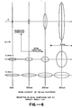
- this is the result of differential focal strength optics, as best diagrammatically illustrated in Figures 2C, 2D and 2E.
- arrangement 42 intercepts expanding electron beam 24 (indicated by dotted lines in Figures 2D and 2E) and "focuses" it onto target 26 (also indicated by dotted lines in Figures 2D and 2E) with different focal strengths in the azimuthal and radial planes.
- the convergence of the focused beam in the radial plane is substantially less than the convergence of the beam in the scan plane.
- the cross-section of this beam at the target is elliptical in shape, as best seen in Figure 2C.
- the major axis of this ellipse lies in the radial direction while the minor axis lies in the azimuthal direction.
- the major axis is always maintained in the radial direction, i.e. perpendicular to the scan path, while the minor axis is always maintained tangential to the scan path.
- the reason for providing differential focal strength beam optics is to reduce the convergence of the electron beam 24 and so increase its width in the radial plane, while still maintaining the position of the waist of the beam in the scan plane at the location of the target 26.
- This reduces the mutual repulsion of the electrons in the space-charge limited beam, compared to the repulsion in a beam with circular cross-section, and so the size of the beam waist in the scan plane, which is the azimuthal width, D a of the electron beam spot on the target, is decreased. Since D a is also the azimuthal width of the X-ray beam effective focal spot, the spatial resolution of the scanner is improved.
- D is also the azimuthal width of the X-ray beam effective focal spot
- the electron beam spot becomes elliptical in form.
- the orientation of the ellipse on the target as well as the difference in focal strength between the two planes are controlled by the quadrupole coils within the dipole.
- the increased radial width of the electron beam spot is of no concern since the axial width of the X-ray beam effective focal spot does not depend on this radial width alone, but can be reduced by modifying the angle of the surface 30 of the target. This is best exemplified in Figures 2F and 2G which diagrammatically illustrate the interrelation between the surface 30 of target 26 and the electron and X-ray beams 24 and 28.
- Figure 2F specifically illustrates how the electron beam impinges target surface 30 in the radial plane.
- the X-ray beam 28 resulting from the impingement of the electron beam with the target is shown in the same plane. Note that, because of the angular relationship between the incoming electron beam and the target surface, the axial width of the X-ray beam effective focal spot is substantially smaller than the radial width of the electron beam spot. It should be apparent from Figure 2F that the angular relationship between the incoming beam and the target surface can be varied so as to vary the relationship between the electron beam spot radial width and the X-ray beam effective focal spot axial width in the same plane.
- the X-ray beam effective focal spot axial width in the radial plane can be made to be narrower than the electron beam spot in the same plane merely by providing the appropriate angular relationship between the electron beam and target surface. This has the same effect with respect to the X-ray beam as reducing the size of the electron beam in the same plane without having to actually do so.
- the azimuthal width of the X-ray beam effective focal spot in the scan plane is equal to the width of the electron beam spot in the same plane, regardless of the actual angle between the electron beam and the target surface.
- the electron beam spot can be reduced in the scan plane at the expense of the beam size in the radial plane by providing the previously described differential focal strength beam optics.
- the additional width in this plane can be compensated for by the angular relationship between the electron beam and the target.
- the minor axis which lies in the scan plane and which cannot be compensated for by the angular relationship just mentioned is made as small as is required.
- the parameter S is given by
- the expanding section of the beam in the scanner is cylindrically symmetric.
- eqns. (1) reduce to: where r is the beam radius.
- the azimuthal diameter of the X-ray beam effective focal spot is reduced by a factor of 5.3, while the axial diameter increases by only a factor of 2.0. This increase can be further reduced by modifying the target angle.
- differential focal strength electron beam optics may-be used in a scanning electron beam computed tomography scanner to reduce the X-ray beam azimuthal effective focal spot width with only a moderate increase in the axial beam spot width.
- This effect is a result of the properties of a space-charge limited elliptical electron beam and can only be achieved if the beam is focused more strongly in the scan plane than in the radial plane so that in general the waist in the scan plane occurs first or very close to the radial plane waist.
- scanner 10 could be designed to provide a different positional relationship between its various components without departing from the present invention.
Landscapes
- Health & Medical Sciences (AREA)
- Life Sciences & Earth Sciences (AREA)
- Engineering & Computer Science (AREA)
- Medical Informatics (AREA)
- Radiology & Medical Imaging (AREA)
- Biomedical Technology (AREA)
- Biophysics (AREA)
- High Energy & Nuclear Physics (AREA)
- Veterinary Medicine (AREA)
- Nuclear Medicine, Radiotherapy & Molecular Imaging (AREA)
- Optics & Photonics (AREA)
- Pathology (AREA)
- Public Health (AREA)
- Physics & Mathematics (AREA)
- Heart & Thoracic Surgery (AREA)
- Molecular Biology (AREA)
- Surgery (AREA)
- Animal Behavior & Ethology (AREA)
- General Health & Medical Sciences (AREA)
- Pulmonology (AREA)
- Theoretical Computer Science (AREA)
- Apparatus For Radiation Diagnosis (AREA)
- X-Ray Techniques (AREA)
- Analysing Materials By The Use Of Radiation (AREA)
Applications Claiming Priority (2)
| Application Number | Priority Date | Filing Date | Title |
|---|---|---|---|
| US50013683A | 1983-06-01 | 1983-06-01 | |
| US500136 | 1983-06-01 |
Publications (2)
| Publication Number | Publication Date |
|---|---|
| EP0127983A2 true EP0127983A2 (de) | 1984-12-12 |
| EP0127983A3 EP0127983A3 (de) | 1986-09-17 |
Family
ID=23988194
Family Applications (1)
| Application Number | Title | Priority Date | Filing Date |
|---|---|---|---|
| EP84303494A Withdrawn EP0127983A3 (de) | 1983-06-01 | 1984-05-23 | Abtasten der Elektronenstrahlen in einem rechnergestützten Abtast-Tomographen |
Country Status (2)
| Country | Link |
|---|---|
| EP (1) | EP0127983A3 (de) |
| JP (1) | JPS6012656A (de) |
Cited By (7)
| Publication number | Priority date | Publication date | Assignee | Title |
|---|---|---|---|---|
| DE4139150C1 (en) * | 1991-11-28 | 1993-06-24 | Siemens Ag, 8000 Muenchen, De | Computer tomograph with part ring formed X=ray source and detector - has double ring system without complementary interpolation |
| DE19639918A1 (de) * | 1996-09-27 | 1998-04-30 | Siemens Ag | Röntgengerät mit einer Röntgenröhre mit Variofokus |
| DE19639920A1 (de) * | 1996-09-27 | 1998-04-30 | Siemens Ag | Röntgenröhre mit variablem Fokus |
| US6160869A (en) * | 1998-10-01 | 2000-12-12 | Imatron, Inc. | Chicane magnet focusing system and deflection magnet for a scanning electron beam computed tomography system |
| EP1675153A1 (de) * | 2004-08-20 | 2006-06-28 | Satoshi Ohsawa | Verfahren zur Erzeugung von Röntgenstrahlen und Apparat zur Erzeugung von Röntgenstrahlen |
| US7653178B2 (en) | 2004-08-20 | 2010-01-26 | Satoshi Ohsawa | X-ray generating method, and X-ray generating apparatus |
| US20240395491A1 (en) * | 2023-05-22 | 2024-11-28 | Nautilus Xray, Inc. | Compact x-ray electron beam scan tube, system and method |
Family Cites Families (4)
| Publication number | Priority date | Publication date | Assignee | Title |
|---|---|---|---|---|
| GB1564309A (en) * | 1975-09-11 | 1980-04-10 | Jeol Ltd | Apparatus for obtaining an x-ray image of a slice plane ofan object |
| US4130759A (en) * | 1977-03-17 | 1978-12-19 | Haimson Research Corporation | Method and apparatus incorporating no moving parts, for producing and selectively directing x-rays to different points on an object |
| EP0024325B1 (de) * | 1979-08-16 | 1983-09-21 | General Electric Company | Röntgentomographiesystem mit elektronischer Abtastung |
| US4352021A (en) * | 1980-01-07 | 1982-09-28 | The Regents Of The University Of California | X-Ray transmission scanning system and method and electron beam X-ray scan tube for use therewith |
-
1984
- 1984-05-23 EP EP84303494A patent/EP0127983A3/de not_active Withdrawn
- 1984-06-01 JP JP59112885A patent/JPS6012656A/ja active Pending
Cited By (13)
| Publication number | Priority date | Publication date | Assignee | Title |
|---|---|---|---|---|
| DE4139150C1 (en) * | 1991-11-28 | 1993-06-24 | Siemens Ag, 8000 Muenchen, De | Computer tomograph with part ring formed X=ray source and detector - has double ring system without complementary interpolation |
| US5377249A (en) * | 1991-11-28 | 1994-12-27 | Siemens Aktiengesellschaft | Computer tomography apparatus having a partial ring x-ray source and a partial ring detector |
| DE19639920C2 (de) * | 1996-09-27 | 1999-08-26 | Siemens Ag | Röntgenröhre mit variablem Fokus |
| DE19639920A1 (de) * | 1996-09-27 | 1998-04-30 | Siemens Ag | Röntgenröhre mit variablem Fokus |
| US5812632A (en) * | 1996-09-27 | 1998-09-22 | Siemens Aktiengesellschaft | X-ray tube with variable focus |
| US5822395A (en) * | 1996-09-27 | 1998-10-13 | Siemens Aktiengesellschaft | X-ray apparatus having an x-ray tube with vario-focus |
| DE19639918A1 (de) * | 1996-09-27 | 1998-04-30 | Siemens Ag | Röntgengerät mit einer Röntgenröhre mit Variofokus |
| DE19639918C2 (de) * | 1996-09-27 | 2001-02-22 | Siemens Ag | Röntgengerät mit einer Röntgenröhre mit Variofokus |
| US6160869A (en) * | 1998-10-01 | 2000-12-12 | Imatron, Inc. | Chicane magnet focusing system and deflection magnet for a scanning electron beam computed tomography system |
| EP1675153A1 (de) * | 2004-08-20 | 2006-06-28 | Satoshi Ohsawa | Verfahren zur Erzeugung von Röntgenstrahlen und Apparat zur Erzeugung von Röntgenstrahlen |
| US7359485B2 (en) | 2004-08-20 | 2008-04-15 | Satoshi Ohsawa | X-ray generating method and X-ray generating apparatus |
| US7653178B2 (en) | 2004-08-20 | 2010-01-26 | Satoshi Ohsawa | X-ray generating method, and X-ray generating apparatus |
| US20240395491A1 (en) * | 2023-05-22 | 2024-11-28 | Nautilus Xray, Inc. | Compact x-ray electron beam scan tube, system and method |
Also Published As
| Publication number | Publication date |
|---|---|
| JPS6012656A (ja) | 1985-01-23 |
| EP0127983A3 (de) | 1986-09-17 |
Similar Documents
| Publication | Publication Date | Title |
|---|---|---|
| US5719914A (en) | Method for correcting spherical aberration of the electron beam in a scanning electron beam computed tomography system | |
| US5132544A (en) | System for irradiating a surface with atomic and molecular ions using two dimensional magnetic scanning | |
| US6438207B1 (en) | X-ray tube having improved focal spot control | |
| US4730353A (en) | X-ray tube apparatus | |
| EP0752198B1 (de) | Ausseraxial-abtastendes, rechnergestütztes elektronenstrahl-tomographiesystem | |
| JP3975363B2 (ja) | 原子及び分子イオンで表面を照射するために有用な振動磁場をワーキング・ギャップにおいて生成するためのシステム及び方法 | |
| JP3730666B2 (ja) | 大電流リボンビーム注入装置 | |
| EP0117729A2 (de) | Einrichtung und Verfahren zum Steuern der Elektronenstrahlen in einem rechnergestützten Abtast-Tomographen mit Hilfe fokussierender Ionen | |
| US5548630A (en) | X-ray radiator having an electron source for sending a beam of electrons along an elongated anode | |
| US6777882B2 (en) | Ion beam generator | |
| US10121629B2 (en) | Angled flat emitter for high power cathode with electrostatic emission control | |
| EP3268976B1 (de) | Röntgenröhre mit magnetischen vierpolen zur fokussierung und magnetischen dipolen zur lenkung | |
| US6635889B2 (en) | Ion implantation apparatus suited for low energy ion implantation and tuning method for ion source system thereof | |
| EP0127983A2 (de) | Abtasten der Elektronenstrahlen in einem rechnergestützten Abtast-Tomographen | |
| EP0581440B1 (de) | Ionenstrahl-Abrasterungsvorrichtung | |
| JP2002528878A (ja) | 可変結像スポットサイズを提供するx線管 | |
| US7872241B2 (en) | Method and apparatus for production and maintenance of electron beam space-charge neutralization | |
| US6160869A (en) | Chicane magnet focusing system and deflection magnet for a scanning electron beam computed tomography system | |
| WO2000041205A1 (en) | Apparatus and method for monitoring and tuning an ion beam in ion implantation apparatus | |
| WO1993012533A1 (en) | Rotable ion controlling electrode assembly with no offset or deflection of low energy electrons for a scanning electron beam computed tomography scanner | |
| US6670625B1 (en) | Method and apparatus for correcting multipole aberrations of an electron beam in an EBT scanner | |
| WO1995017003A1 (en) | Method and apparatus for electron beam focusing adjustment in a scanning electron beam computed tomography scanner | |
| EP3226277A1 (de) | Abgewinkelter flacher emitter für hochleistungskathode mit elektrostatischer emissionskontrolle | |
| US10102999B2 (en) | Asymmetric core quadrupole with concave pole tips | |
| US10468222B2 (en) | Angled flat emitter for high power cathode with electrostatic emission control |
Legal Events
| Date | Code | Title | Description |
|---|---|---|---|
| PUAI | Public reference made under article 153(3) epc to a published international application that has entered the european phase |
Free format text: ORIGINAL CODE: 0009012 |
|
| AK | Designated contracting states |
Designated state(s): DE FR GB IT NL SE |
|
| PUAL | Search report despatched |
Free format text: ORIGINAL CODE: 0009013 |
|
| AK | Designated contracting states |
Kind code of ref document: A3 Designated state(s): DE FR GB IT NL SE |
|
| STAA | Information on the status of an ep patent application or granted ep patent |
Free format text: STATUS: THE APPLICATION IS DEEMED TO BE WITHDRAWN |
|
| 18D | Application deemed to be withdrawn |
Effective date: 19861203 |
|
| RIN1 | Information on inventor provided before grant (corrected) |
Inventor name: RAND, ROY EDWARD |