EP0128003A2 - Zweistufiges richtungsabhängiges Regelventil - Google Patents
Zweistufiges richtungsabhängiges Regelventil Download PDFInfo
- Publication number
- EP0128003A2 EP0128003A2 EP84303630A EP84303630A EP0128003A2 EP 0128003 A2 EP0128003 A2 EP 0128003A2 EP 84303630 A EP84303630 A EP 84303630A EP 84303630 A EP84303630 A EP 84303630A EP 0128003 A2 EP0128003 A2 EP 0128003A2
- Authority
- EP
- European Patent Office
- Prior art keywords
- spool
- valve
- main
- pilot
- solenoid
- Prior art date
- Legal status (The legal status is an assumption and is not a legal conclusion. Google has not performed a legal analysis and makes no representation as to the accuracy of the status listed.)
- Withdrawn
Links
Images


Classifications
-
- F—MECHANICAL ENGINEERING; LIGHTING; HEATING; WEAPONS; BLASTING
- F15—FLUID-PRESSURE ACTUATORS; HYDRAULICS OR PNEUMATICS IN GENERAL
- F15B—SYSTEMS ACTING BY MEANS OF FLUIDS IN GENERAL; FLUID-PRESSURE ACTUATORS, e.g. SERVOMOTORS; DETAILS OF FLUID-PRESSURE SYSTEMS, NOT OTHERWISE PROVIDED FOR
- F15B13/00—Details of servomotor systems ; Valves for servomotor systems
- F15B13/02—Fluid distribution or supply devices characterised by their adaptation to the control of servomotors
- F15B13/04—Fluid distribution or supply devices characterised by their adaptation to the control of servomotors for use with a single servomotor
- F15B13/042—Fluid distribution or supply devices characterised by their adaptation to the control of servomotors for use with a single servomotor operated by fluid pressure
- F15B13/043—Fluid distribution or supply devices characterised by their adaptation to the control of servomotors for use with a single servomotor operated by fluid pressure with electrically-controlled pilot valves
- F15B13/0433—Fluid distribution or supply devices characterised by their adaptation to the control of servomotors for use with a single servomotor operated by fluid pressure with electrically-controlled pilot valves the pilot valves being pressure control valves
-
- F—MECHANICAL ENGINEERING; LIGHTING; HEATING; WEAPONS; BLASTING
- F15—FLUID-PRESSURE ACTUATORS; HYDRAULICS OR PNEUMATICS IN GENERAL
- F15B—SYSTEMS ACTING BY MEANS OF FLUIDS IN GENERAL; FLUID-PRESSURE ACTUATORS, e.g. SERVOMOTORS; DETAILS OF FLUID-PRESSURE SYSTEMS, NOT OTHERWISE PROVIDED FOR
- F15B13/00—Details of servomotor systems ; Valves for servomotor systems
- F15B13/02—Fluid distribution or supply devices characterised by their adaptation to the control of servomotors
- F15B13/04—Fluid distribution or supply devices characterised by their adaptation to the control of servomotors for use with a single servomotor
- F15B13/0401—Valve members; Fluid interconnections therefor
- F15B13/0402—Valve members; Fluid interconnections therefor for linearly sliding valves, e.g. spool valves
-
- F—MECHANICAL ENGINEERING; LIGHTING; HEATING; WEAPONS; BLASTING
- F15—FLUID-PRESSURE ACTUATORS; HYDRAULICS OR PNEUMATICS IN GENERAL
- F15B—SYSTEMS ACTING BY MEANS OF FLUIDS IN GENERAL; FLUID-PRESSURE ACTUATORS, e.g. SERVOMOTORS; DETAILS OF FLUID-PRESSURE SYSTEMS, NOT OTHERWISE PROVIDED FOR
- F15B13/00—Details of servomotor systems ; Valves for servomotor systems
- F15B13/02—Fluid distribution or supply devices characterised by their adaptation to the control of servomotors
- F15B13/04—Fluid distribution or supply devices characterised by their adaptation to the control of servomotors for use with a single servomotor
- F15B13/042—Fluid distribution or supply devices characterised by their adaptation to the control of servomotors for use with a single servomotor operated by fluid pressure
- F15B13/043—Fluid distribution or supply devices characterised by their adaptation to the control of servomotors for use with a single servomotor operated by fluid pressure with electrically-controlled pilot valves
- F15B13/0435—Fluid distribution or supply devices characterised by their adaptation to the control of servomotors for use with a single servomotor operated by fluid pressure with electrically-controlled pilot valves the pilot valves being sliding valves
-
- F—MECHANICAL ENGINEERING; LIGHTING; HEATING; WEAPONS; BLASTING
- F16—ENGINEERING ELEMENTS AND UNITS; GENERAL MEASURES FOR PRODUCING AND MAINTAINING EFFECTIVE FUNCTIONING OF MACHINES OR INSTALLATIONS; THERMAL INSULATION IN GENERAL
- F16K—VALVES; TAPS; COCKS; ACTUATING-FLOATS; DEVICES FOR VENTING OR AERATING
- F16K31/00—Actuating devices; Operating means; Releasing devices
- F16K31/12—Actuating devices; Operating means; Releasing devices actuated by fluid
- F16K31/42—Actuating devices; Operating means; Releasing devices actuated by fluid by means of electrically-actuated members in the supply or discharge conduits of the fluid motor
- F16K31/423—Actuating devices; Operating means; Releasing devices actuated by fluid by means of electrically-actuated members in the supply or discharge conduits of the fluid motor the actuated members consisting of multiple way valves
- F16K31/426—Actuating devices; Operating means; Releasing devices actuated by fluid by means of electrically-actuated members in the supply or discharge conduits of the fluid motor the actuated members consisting of multiple way valves the actuated valves being cylindrical sliding valves
Definitions
- This invention relates to two-stage directional control valves and more particularly, to such valves which are solenoid operated.
- a pilot valve which is used to drive hydraulically a main or second stage valve, the pilot valve being controlled by at least one solenoid.
- solenoid For a given size of solenoid, there is a limit to the force it can exert which in turn limits the size and stroke of the pilot valve.
- the main or second stage spool cannot be moved when the residual pressure pertaining when the pilot valve is in the null or central position is insufficient to provide pilot pressure to move the main valve by use of the pilot valve spool.
- a solenoid-operated, two-stage hydraulic spool valve comprising pilot valve means and a main valve with the pilot valve means comprising two control devices associated with respective ends of the spool of the main valve, at least one control device comprising a solenoid and a pilot valve spool, in use each control device being operable physically to move the main valve spool during an initial portion of the movement of the latter from a null position to an offset position in which hydraulic fluid is passed to a load, movement of the main valve spool beyond said initial portion being effected hydraulically on opening of the pilot valve means; the hydraulic spool valve further comprising means for equalising the hydraulic pressure across each control device.
- each control device is in the form of a solenoid and associated pilot valve spool although one device may be in the form of a spring offset arrangement.
- the or each solenoid when energised to move the main valve spool, may be arranged to move the main valve spool through the agency of the associated pilot valve spool.
- the or each solenoid may be arranged to move the main valve spool indirectly through mechanical linkages between the main spool valve and the solenoid or associated pilot valve spool.
- the pressure equalisation means may comprise a channel interconnecting hydraulically the ends of the or each pilot valve spool and the channel may be provided externally or internally of the pilot valve spool.
- the present invention provides a valve which is, in effect, a hybrid of a direct acting valve and a pilot-assisted valve, whereby the size and stroke of the main valve can be increased for a given size of solenoid employed with the pilot valve by arranging for the or each solenoid to operate physically (directly or indirectly) on the main valve before the latter is operated entirely hydraulically.
- the valve is of the open centre type and comprises a main housing or body 1 in which is slidably mounted a spool 2 of the main or second stage of the two-way valve.
- the main spool 2 is centred in conventional fashion by two compression springs 3 acting on the respective ends of the spool via annular members or washers 4 with respect to which the spool is slidable by way of portions 5 of reduced diameter which extend through the corresponding member. Movement of the members 4 axially of the valve is limited in one direction by a step 6 formed in the housing 1.
- the main spool 2 is provided with four lands 7, 8, 9 and 11 between which are three waisted portions 12, 13 and 14, the lands controlling the flow of fluid under pressure to a load, in the form of a double-acting cylinder 15, through one or other of two service ports 16, 17 formed in the housing 1.
- An inlet or pressure port 18 is also provided in the housing 1, together with a tank loop 19. Since the valve is of the open-centre type, the pressure port 18 is connected to tank via the tank loop 19 when the valve is in the centre or null position of Figure 1 but this only gives rise to a small pressure drop across the valve.
- Each end of the main housing 1 threadedly and sealingly receives an end cap 21 which houses a pilot valve 22 comprising a spool 23 controlled by a solenoid 24 having a push pin 25 engageable with one end of the spool.
- the other end of the spool 23 is engageable with one end of the main spool.
- a centring spring 26 for each pilot spool 23 operates between the associated annular member or washer 4 of the main valve and a similar member 27 through which the spool 23 is slidable, the member 27 being limited in movement axially of the valve by the inner end of the end cap 21.
- Each pilot valve 22 is provided with an inlet or pressure port 28 which is connected to the pressure port 18 of the main valve by aligned channels 29 in the corresponding end cap 21 and main housing 1.
- a tank port 31 is also provided in each pilot valve 22 which port is connected to tank, via aligned channels 32 in the corresponding end cap and main valve housing 1 and via the tank loop 19 of the main valve.
- What amounts to a service port is provided at the inner end of each pilot valve by way of a land 33 on the spool 23 which, when not in sealing engagement with the corresponding portion 34 of the pilot valve housing or end cap 21, allows fluid under pressure to be admitted to the associated end chamber 35 of the main valve as will be described in greater detail.
- the left-hand end cap 21 of Figure 1 shows a channel 36 extending between the outer end of the spool 23 and the associated end chamber 35 of the main valve and this serves to equalise the pressure across the pilot valve.
- An alternative form of pressure equalisation means is shown at the right-hand end of Figure 1 in the form of an axial bore 37 through the pilot valve spool 23 which is intersected by radial bores 38 towards respective ends of the spool to ensure that the main bore is not sealed by the engagement of the ends of the spool with the main spool 2 and the solenoid push pin 25, respectively.
- cross cuts could be provided in the spool end faces.
- the centring springs 3 and 26 are designed such that the solenoid 24 is capable of overcoming the forces exerted by both pilot centring springs 26 and one main valve centring spring 3.
- the solenoid 24 is operative to move both the pilot spool 23 and the main spool 2 effectively without any hydraulic assistance although there may be some small flow of fluid depending on the characteristics of the valve.
- the land 33 clears the portion 34 of the valve housing or end cap 21 as shown in the lower half of Figure 2, whereupon fluid under pressure from the main valve pressure port 18 is admitted to the left-hand end chamber 35 of the main valve via the channels 29 and pilot pressure port 28.
- the pressure fluid so admitted acts on the end of the main valve spool 2 to further its movement to the right, there coming a point when the solenoid 24 is at the end of its stroke so that further movement of the main spool hydraulically breaks the contact between the latter and the left-hand pilot spool 23 as shown in the lower half of Figure 2.
- the main spool 2 is designed such that when either one of the solenoids 24 completes its stroke, the interconnections within the valve result in fluid under pressure being directed to one end or other of the load 15 and the resistance of the latter creates a pressure in the system between the pump 39 ( Figure 4) and the load, including the pressure port 18. Then, as already described, fluid under pressure is admitted to the appropriate end chamber 35 forcing the main spool 2 to complete its travel.
- the pressure across each pilot spool 23 is equalised by the channel 36 (or other means) to hold the spool in'the position shown in the lower half of Figure 2 under the influence of the solenoid force and the force of the centring spring 26.
- Figure 3 shows the extreme left-hand position of the left-hand pilot spool 23, the equivalent position being adopted by the right-hand pilot spool on completion of the main spool travel described above.
- the centring spring 26 returns the pilot spool 23 to the null position of Figure 2 (upper half), whereupon the left-hand pilot pressure port 28 is now isolated from the associated main valve end chamber 35 which is thus connected to tank via the channel 36, the pilot tank port 31, channels 32 and tank loop 19.
- the pilot pressure in the left-hand end chamber 35 of the main valve will then decay and the main spool 2 will be returned to the null or central position by the right-hand centring spring 3.
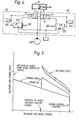
- Figure 4 shows an hydraulic circuit diagram of the valve of Figure 1 with like components ascribed similar reference numerals.
- the broken lines 41 indicate the mechanical connections between the solenoids 24 and the pilot and main valves which in the embodiment of Figure 1 are direct connections. However, it is possible to have indirect mechanical connections by employing linkages, for example, between the pilot spools or solenoids and the main spool.
- Figure 5 is a graph of solenoid and centring spring forces against solenoid and spool strokes useful in appreciating the operation of the embodiment of Figure 1.
- the channels 29 associated with the respective spool valves 22 may be fitted with flow control and/or pressure reducing devices.
- the present invention permits the use of a relatively large main spool in a circuit where no residual pressure or pilot pressure is available or desirable and yet allows that spool to be operated by a solenoid which is small enough normally to require the provision of a pilot pressure supply.
- the main spool 2 has a diameter of 18mm and the solenoid is of a size normally associated with a spool having a l2mm diameter.
- the movement of the main spool 2 by the direct action of one or other of the solenoids 24 is arranged to be about 3mm, approximately half of the maximum stroke of the spool.
- one solenoid and spool pair can be replaced by a conventional spring offset arrangement.
- the pressure equalisation means will be inherent in the spring offset arrangement so that no special provision need be made in this respect.
- the present invention combines features of a direct acting valve and a pilot-assisted valve in a highly effective manner without any significant increase in cost.
Landscapes
- Engineering & Computer Science (AREA)
- General Engineering & Computer Science (AREA)
- Mechanical Engineering (AREA)
- Physics & Mathematics (AREA)
- Fluid Mechanics (AREA)
- Fluid-Driven Valves (AREA)
- Magnetically Actuated Valves (AREA)
- Multiple-Way Valves (AREA)
Applications Claiming Priority (2)
| Application Number | Priority Date | Filing Date | Title |
|---|---|---|---|
| GB8315078 | 1983-06-01 | ||
| GB838315078A GB8315078D0 (en) | 1983-06-01 | 1983-06-01 | Two-stage directional control valves |
Publications (2)
| Publication Number | Publication Date |
|---|---|
| EP0128003A2 true EP0128003A2 (de) | 1984-12-12 |
| EP0128003A3 EP0128003A3 (de) | 1985-09-18 |
Family
ID=10543658
Family Applications (1)
| Application Number | Title | Priority Date | Filing Date |
|---|---|---|---|
| EP84303630A Withdrawn EP0128003A3 (de) | 1983-06-01 | 1984-05-30 | Zweistufiges richtungsabhängiges Regelventil |
Country Status (3)
| Country | Link |
|---|---|
| EP (1) | EP0128003A3 (de) |
| JP (1) | JPS608584A (de) |
| GB (1) | GB8315078D0 (de) |
Cited By (5)
| Publication number | Priority date | Publication date | Assignee | Title |
|---|---|---|---|---|
| EP0637692A1 (de) * | 1993-07-06 | 1995-02-08 | Caterpillar Inc. | Hydraulisches proportionalventil mit Hubsteuerung |
| WO2009030249A1 (de) * | 2007-09-03 | 2009-03-12 | Festo Ag & Co. Kg | Mehrwegeventil |
| CN109404561A (zh) * | 2018-09-30 | 2019-03-01 | 陕西科技大学 | 一种磨煤分配阀 |
| US10344885B2 (en) | 2013-08-01 | 2019-07-09 | Moog Controls Limited | Hydraulic servovalves |
| CN112283419A (zh) * | 2020-11-27 | 2021-01-29 | 力源液压(苏州)有限公司 | 一种实现两个压力级别溢流的缓冲阀 |
Families Citing this family (1)
| Publication number | Priority date | Publication date | Assignee | Title |
|---|---|---|---|---|
| CN102165236B (zh) | 2008-12-22 | 2013-12-04 | 爱信精机株式会社 | 旋转式阀装置 |
Family Cites Families (4)
| Publication number | Priority date | Publication date | Assignee | Title |
|---|---|---|---|---|
| FR1333554A (fr) * | 1962-09-14 | 1963-07-26 | Teves Kg Alfred | Circuit hydraulique pour valve à tiroir |
| DE1256017B (de) * | 1963-05-13 | 1967-12-07 | Mac Valves Inc | Druckmittelbetaetigter Steuerschieber mit Vorsteuerung |
| GB1170281A (en) * | 1966-02-16 | 1969-11-12 | Dowty Technical Dev Ltd | Electro-Hydraulic Servo Valves. |
| GB1261134A (en) * | 1969-11-05 | 1972-01-19 | Ch Traktorny Zd | Directional control valves for the power cylinders of operating elements of machines |
-
1983
- 1983-06-01 GB GB838315078A patent/GB8315078D0/en active Pending
-
1984
- 1984-05-30 EP EP84303630A patent/EP0128003A3/de not_active Withdrawn
- 1984-06-01 JP JP11110584A patent/JPS608584A/ja active Pending
Cited By (5)
| Publication number | Priority date | Publication date | Assignee | Title |
|---|---|---|---|---|
| EP0637692A1 (de) * | 1993-07-06 | 1995-02-08 | Caterpillar Inc. | Hydraulisches proportionalventil mit Hubsteuerung |
| WO2009030249A1 (de) * | 2007-09-03 | 2009-03-12 | Festo Ag & Co. Kg | Mehrwegeventil |
| US10344885B2 (en) | 2013-08-01 | 2019-07-09 | Moog Controls Limited | Hydraulic servovalves |
| CN109404561A (zh) * | 2018-09-30 | 2019-03-01 | 陕西科技大学 | 一种磨煤分配阀 |
| CN112283419A (zh) * | 2020-11-27 | 2021-01-29 | 力源液压(苏州)有限公司 | 一种实现两个压力级别溢流的缓冲阀 |
Also Published As
| Publication number | Publication date |
|---|---|
| GB8315078D0 (en) | 1983-07-06 |
| JPS608584A (ja) | 1985-01-17 |
| EP0128003A3 (de) | 1985-09-18 |
Similar Documents
| Publication | Publication Date | Title |
|---|---|---|
| CA1228280A (en) | Pilot valves for two-stage hydraulic devices | |
| US3875849A (en) | Electro-hydraulic proportional servo actuator | |
| US4011891A (en) | Proportional flow control valve | |
| US4543875A (en) | Electro-hydraulic directional control valve | |
| US3797525A (en) | Pilot valve | |
| US4611632A (en) | Hydraulic solenoid valve structure | |
| US2650609A (en) | Hydraulic valve | |
| CA1261233A (en) | Lockout valve | |
| US6871574B2 (en) | Hydraulic control valve assembly having dual directional spool valves with pilot operated check valves | |
| US4126293A (en) | Feathering valve assembly | |
| US7422033B2 (en) | Position feedback pilot valve actuator for a spool control valve | |
| US6354185B1 (en) | Flow manager module | |
| JP3193729B2 (ja) | 位置制御される比例方向弁 | |
| CA1195206A (en) | Electrohydraulic valve | |
| US4903727A (en) | Safety valve | |
| US4617967A (en) | Two-stage hydraulic valves | |
| EP0128003A2 (de) | Zweistufiges richtungsabhängiges Regelventil | |
| US3744518A (en) | Directional control valve | |
| US4922963A (en) | Hydraulic servovalve | |
| US5209263A (en) | Pilot valve assembly | |
| JPS62501983A (ja) | 負荷応答方向制御弁の負荷検出回路 | |
| GB2225168A (en) | Electromagnetic valve device | |
| US3790127A (en) | Hydraulic valve | |
| US3595271A (en) | Directional flow control valve with float and check valve structure | |
| US5226346A (en) | Axial piston type pressure medium servomotor control device |
Legal Events
| Date | Code | Title | Description |
|---|---|---|---|
| PUAI | Public reference made under article 153(3) epc to a published international application that has entered the european phase |
Free format text: ORIGINAL CODE: 0009012 |
|
| AK | Designated contracting states |
Designated state(s): DE FR GB IT SE |
|
| PUAL | Search report despatched |
Free format text: ORIGINAL CODE: 0009013 |
|
| AK | Designated contracting states |
Designated state(s): DE FR GB IT SE |
|
| 17P | Request for examination filed |
Effective date: 19851016 |
|
| STAA | Information on the status of an ep patent application or granted ep patent |
Free format text: STATUS: THE APPLICATION HAS BEEN WITHDRAWN |
|
| 18W | Application withdrawn |
Withdrawal date: 19860505 |
|
| RIN1 | Information on inventor provided before grant (corrected) |
Inventor name: SHAW, CHARLES ANTHONY |