EP0128030A2 - Präzisionsführung - Google Patents
Präzisionsführung Download PDFInfo
- Publication number
- EP0128030A2 EP0128030A2 EP84303708A EP84303708A EP0128030A2 EP 0128030 A2 EP0128030 A2 EP 0128030A2 EP 84303708 A EP84303708 A EP 84303708A EP 84303708 A EP84303708 A EP 84303708A EP 0128030 A2 EP0128030 A2 EP 0128030A2
- Authority
- EP
- European Patent Office
- Prior art keywords
- bearing
- elastomeric
- shaft
- elastomeric medium
- medium
- Prior art date
- Legal status (The legal status is an assumption and is not a legal conclusion. Google has not performed a legal analysis and makes no representation as to the accuracy of the status listed.)
- Withdrawn
Links
Images

Classifications
-
- F—MECHANICAL ENGINEERING; LIGHTING; HEATING; WEAPONS; BLASTING
- F16—ENGINEERING ELEMENTS AND UNITS; GENERAL MEASURES FOR PRODUCING AND MAINTAINING EFFECTIVE FUNCTIONING OF MACHINES OR INSTALLATIONS; THERMAL INSULATION IN GENERAL
- F16C—SHAFTS; FLEXIBLE SHAFTS; ELEMENTS OR CRANKSHAFT MECHANISMS; ROTARY BODIES OTHER THAN GEARING ELEMENTS; BEARINGS
- F16C29/00—Bearings for parts moving only linearly
- F16C29/12—Arrangements for adjusting play
-
- B—PERFORMING OPERATIONS; TRANSPORTING
- B23—MACHINE TOOLS; METAL-WORKING NOT OTHERWISE PROVIDED FOR
- B23Q—DETAILS, COMPONENTS, OR ACCESSORIES FOR MACHINE TOOLS, e.g. ARRANGEMENTS FOR COPYING OR CONTROLLING; MACHINE TOOLS IN GENERAL CHARACTERISED BY THE CONSTRUCTION OF PARTICULAR DETAILS OR COMPONENTS; COMBINATIONS OR ASSOCIATIONS OF METAL-WORKING MACHINES, NOT DIRECTED TO A PARTICULAR RESULT
- B23Q1/00—Members which are comprised in the general build-up of a form of machine, particularly relatively large fixed members
- B23Q1/25—Movable or adjustable work or tool supports
- B23Q1/26—Movable or adjustable work or tool supports characterised by constructional features relating to the co-operation of relatively movable members; Means for preventing relative movement of such members
- B23Q1/262—Movable or adjustable work or tool supports characterised by constructional features relating to the co-operation of relatively movable members; Means for preventing relative movement of such members with means to adjust the distance between the relatively slidable members
-
- B—PERFORMING OPERATIONS; TRANSPORTING
- B23—MACHINE TOOLS; METAL-WORKING NOT OTHERWISE PROVIDED FOR
- B23Q—DETAILS, COMPONENTS, OR ACCESSORIES FOR MACHINE TOOLS, e.g. ARRANGEMENTS FOR COPYING OR CONTROLLING; MACHINE TOOLS IN GENERAL CHARACTERISED BY THE CONSTRUCTION OF PARTICULAR DETAILS OR COMPONENTS; COMBINATIONS OR ASSOCIATIONS OF METAL-WORKING MACHINES, NOT DIRECTED TO A PARTICULAR RESULT
- B23Q1/00—Members which are comprised in the general build-up of a form of machine, particularly relatively large fixed members
- B23Q1/25—Movable or adjustable work or tool supports
- B23Q1/26—Movable or adjustable work or tool supports characterised by constructional features relating to the co-operation of relatively movable members; Means for preventing relative movement of such members
- B23Q1/28—Means for securing sliding members in any desired position
- B23Q1/287—Means for securing sliding members in any desired position using a hydraulically controlled membrane acting directly upon a sliding member
-
- F—MECHANICAL ENGINEERING; LIGHTING; HEATING; WEAPONS; BLASTING
- F16—ENGINEERING ELEMENTS AND UNITS; GENERAL MEASURES FOR PRODUCING AND MAINTAINING EFFECTIVE FUNCTIONING OF MACHINES OR INSTALLATIONS; THERMAL INSULATION IN GENERAL
- F16C—SHAFTS; FLEXIBLE SHAFTS; ELEMENTS OR CRANKSHAFT MECHANISMS; ROTARY BODIES OTHER THAN GEARING ELEMENTS; BEARINGS
- F16C25/00—Bearings for exclusively rotary movement adjustable for wear or play
- F16C25/02—Sliding-contact bearings
-
- F—MECHANICAL ENGINEERING; LIGHTING; HEATING; WEAPONS; BLASTING
- F16—ENGINEERING ELEMENTS AND UNITS; GENERAL MEASURES FOR PRODUCING AND MAINTAINING EFFECTIVE FUNCTIONING OF MACHINES OR INSTALLATIONS; THERMAL INSULATION IN GENERAL
- F16C—SHAFTS; FLEXIBLE SHAFTS; ELEMENTS OR CRANKSHAFT MECHANISMS; ROTARY BODIES OTHER THAN GEARING ELEMENTS; BEARINGS
- F16C29/00—Bearings for parts moving only linearly
- F16C29/002—Elastic or yielding linear bearings or bearing supports
-
- F—MECHANICAL ENGINEERING; LIGHTING; HEATING; WEAPONS; BLASTING
- F16—ENGINEERING ELEMENTS AND UNITS; GENERAL MEASURES FOR PRODUCING AND MAINTAINING EFFECTIVE FUNCTIONING OF MACHINES OR INSTALLATIONS; THERMAL INSULATION IN GENERAL
- F16C—SHAFTS; FLEXIBLE SHAFTS; ELEMENTS OR CRANKSHAFT MECHANISMS; ROTARY BODIES OTHER THAN GEARING ELEMENTS; BEARINGS
- F16C29/00—Bearings for parts moving only linearly
- F16C29/02—Sliding-contact bearings
-
- F—MECHANICAL ENGINEERING; LIGHTING; HEATING; WEAPONS; BLASTING
- F16—ENGINEERING ELEMENTS AND UNITS; GENERAL MEASURES FOR PRODUCING AND MAINTAINING EFFECTIVE FUNCTIONING OF MACHINES OR INSTALLATIONS; THERMAL INSULATION IN GENERAL
- F16C—SHAFTS; FLEXIBLE SHAFTS; ELEMENTS OR CRANKSHAFT MECHANISMS; ROTARY BODIES OTHER THAN GEARING ELEMENTS; BEARINGS
- F16C2322/00—Apparatus used in shaping articles
- F16C2322/39—General buildup of machine tools, e.g. spindles, slides, actuators
Definitions
- This invention relates to sliding bearings for use in precision slides such as are employed, for example, in precision machine tools such as engine lathes.
- each bearing assembly comprises a bearing block having an internal passageway through which the shaft extends and housing one or more bearing sleeves lined with antifriction material, the bearing sleeve or sleeves being a press fit in the housing. It is necessary to keep the clearance between the relatively sliding surfaces of the sleeve or sleeves and the shaft to a minimum, in order to ensure accurate rectilinear movement of the slide, but with the current practice it is impossible to reduce the clearance to zero and so there is a limit to the accuracy which can be achieved.
- ball bearing assemblies have been employed for the purpose, but apart from the matter of cost, such assemblies have the disadvantage of low load capacity and high starting friction due to dust seals which make it difficult to control the movement of the slide accurately.
- This is achieved in one embodiment by providing, instead of a tubular bearing sleeve which is a press fit into the housing, a resilient split sleeve which may be urged into zero clearance conformity with the shaft surface by a radially inward displacement of the split sleeve caused by urging the elastomeric backing member in a direction transverse to its radial thickness.
- an arcuate resilient bearing plate and one or more flat bearing plates, respectively replace the resilient split sleeve.
- the elastomeric medium is confined between abutment members, at least one of which is adjustable for variably urging the medium-so as to vary said displacement and thereby adjust the clearance between the relatively sliding surfaces to values between zero and any desired amount.
- a precision slide comprising a linear shaft defining a longitudinal axis and a slide member constrained thereby to be moved longitudinally, a bearing assembly comprising a bearing block having an axially extending cavity defining a passageway through which the shaft extends, the cavity having a wall arranged coaxially with the shaft, a resilient bearing member within the cavity, the bearing member having an internal bearing surface in cooperative sliding engagement with the shaft and an external surface spaced radially from the cavity wall, an elastomeric medium substantially filling the space between the sleeve and the cavity wall, said elastomeric medium being urgable in a direction transverse to its thickness so as to cause an inward movement of said internal bearing surface, and means for adjustably displacing the elastomeric medium in said transverse direction for adjustably varying the clearance between said internal bearing surface and the shaft.
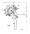
- Figure 5 is a cross-sectional view of the assembly shown in Figure 4.
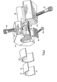
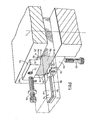
- Figure 6 is an exploded view showing the components of a bearing assembly in accordance with a third embodiment of the invention.
- Figure 7 is a cross-sectional view of the assembly of Figure 6.
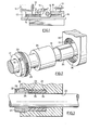
- Figure 1 shows a conventional engineer's lathe, the figure showing particularly the lathe bed 10, headstock 11 with faceplate 12, tailstock 13 and saddle 14 carrying a cross- slide 15.
- the saddle 14 is driven by a lead-screw 16, driven from a gearbox 17, and is constrained by a pair of parallel guide shafts 18, to move along a fixed rectilinear path.
- the saddle is mounted on slide bearings, one such bearing being located for example in the region indicated by the circle 2.
- slide bearings are illustrated in the subsequent figures of the drawings.
- the first bearing assembly comprises a bearing block 20 having a cylindrical bore 19 through which the guide shaft 18 extends.
- the wall of the bore is formed with an annular step 21, serving as an abutment stop as hereinafter described, so as to provide a first cylindrical wall portion 22 which is a sliding fit on the shaft 18, and a second cylindrical wall portion 23 of largerdiameter, both wall portions being arranged coaxially with the shaft 18.
- a bearing member consisting of a resilient split sleeve 24.
- the sleeve 24 is of steel having an internal bearing surface lined with antifriction material such as tetrafluoroethylene, the internal bearing surface being maintained in cooperative sliding engagement with the shaft.
- the external surface of the split sleeve is spaced radi-
- the cavity defining the passageway may be formed as a cylindrical bore, in which case it is preferable that the elastomeric medium be urged by the adjustable abutment member in the axial direction.
- the cavity may be formed as an axially extending channel, in which case the split sleeve will take the form of an arcuate resilient bearing plate, and the urging of the elastomeric backing medium by the adjustable abutment member will be in the circumferential direction.
- the cavity may be formed as an axially extending channel having at least one flat channel wall in generally parallel alignment with a generally flat bearing plate, and the urging of the elastomeric backing medium by the adjustable abutment member being in a direction parallel to the flat channel wall, that is, in a direction transverse to the thickness of the elastomeric medium and the bearing plate.
- the annular space between the sleeve 24 and the wall portion 23 is substantially filled with an elastomeric medium.
- the elastomeric medium takes the form of a tubular sleeve 25 of isotropic elastomeric material such as solid urethane.
- the elastomeric sleeve 25 can be urged in the axial direction, that is, in a direction transverse to its radial thickness, to cause radially inward displacement of the elastomeric medium of the sleeve 25 with resultant radially inward movement of the internal bearing surface of the resilient split sleeve 24.
- the elastomeric sleeve 25 is confined axially between the annular face 21 and the face of an annular plunger 26, which serves as a second abutment stop.
- the plunger 26 has an externally threaded flange portion 29 which is in screw-threaded engagement with an internally threaded wall portion 30 at the end of the cylindrical bore 19.
- the plunger 26, which projects into the annular space between the wall portion 23 and the bearing sleeve 24, can thus be adjusted axially by being rotated, for which purpose an externally accessible part 31 of the plunger provides keying means 32 for engagement by a suitable key.
- the plunger 26 is thus axially adjustable so as to vary the urging of the elastomeric medium, thereby to vary the displacement of the internal surface of the sleeve 24, and so as to thereby vary in a controlled manner the clearance of engagement between resilient split sleeve and the shaft.
- the second bearing assembly is suitable where the saddle 14 is constrained by a pair of parallel guide shafts disposed symmetrically on either side of a centre line C.
- the guide shafts 38 is shown, in order to illustrate the, associated bearing assembly in greater detail, the two bearing assemblies being of the same type.
- Each bearing assembly comprises a bearing block 40 formed with an axially extending open channel 41 defining a passageway through which the shaft 38 extends.
- the channel has a cylindrical wall extending for more than 180° of arc from one longitudinal edge 42 to the other longitudinal edge 43, the edges 42, 43 defining the mouth of the channel.
- the cylindrical wall is coaxial with the shaft 38.
- the shaft 38 is secured to the machine frame 44 by bolts 45 which are positioned so as to extend into the mouth of the channel and so as not to interfere with the bearing.
- a bearing member 46 Located within the channel is a bearing member 46 in the form of an arcuate resilient bearing plate, preferably of steel.
- the member 46 has a concave internal bearing surface 47 coated with a film of antifriction material such as tetrafluoroethylene, and a convex external surface 48 spaced radially from the cylindrical wall of the channel.
- the bearing member 46 does in fact form part of a cylinder arranged coaxially with the channel wall and extending for about the same length of arc.
- An elastomeric medium in this case a partial ring of solid urethane 49 is interposed between the wall of the channel 41 and the bearing member 46, substantially filling the radial space between them.
- the elastomeric medium 49 is urgable in a direction transverse to its thickness so as to cause a radially inward displacement of the elastomeric medium 49 with a resulting inward collapsing movement of the internal surface 47 of the resilient bearing member 46.
- the elastomeric medium 49 is confined between opposed abutment members, namely a first abutment member constituted by a plate 50 which is bolted to the bearing block 40 by a bolt 51 so as to extend along the channel 0 edge 43 in overlapping relation thereto, and a second abutment member constituted by a plate 52.
- the elastomeric medium 49 is also axially confined by the end flanges 27 of bearing block 40.
- the plate 52 is adjustably secured to the bearing block 40 so as to extend along the opposite edge 42 of the channel 41 in overlapping relation thereto.
- the plate 52 is formed with a transverse lip portion 53 which serves as a plunger which projects into the mouth of the channel to engage one longitudinal edge of the elastomeric medium 49.
- the plate 52 is formed with a threaded hole 54 which engages an adjusting screw 55 mounted in a locating bore 56 of the bearing block 40.
- the elastomeric medium 49 is confined between flanges 27 and between opposed circumferentially spaced abutment members 50, 53, the latter abutment member being adjustable so as to urge the elastomeric medium circumferentially so as to vary the clearance between the bearing member 46 and the shaft 38.
- the third bearing assembly is suitable where the saddle is constrained by a pair of parallel guide shafts of uniform non-circular cross-section disposed symmetrically on either side of centre line C.
- the guide shafts 56 having a general rectangular cross-section, is shown in order to illustrate the associated bearing assembly in greater detail, the two bearing assemblies being of the same type. While a guide shaft 56 of rectangular cross-section is shown and such shafts are commonly used in lathe construction, this aspect of the invention is not limited to rectangular guide shafts, but encompasses all guide shafts of uniform cross-section having at least one planar surface parallel to the longitudinal axis of the shaft, which planar surface is in cooperative sliding . engagement with a bearing member.
- the bearing assembly illustrated comprises a bearing block 57 formed with an axially extending channel 58 defining a passageway through which the shaft 56 extends.
- the channel shown has three flat channel walls 59 each arranged at right angles to the adjacent wall, and each being arranged in substantially parallel spaced relationship with the corresponding flat planar surface 60 of the shaft 56.
- the shaft 56 is secured to the machine frame 62 by bolts 63 which are positioned so as to extend into the mouth of the channel 58 and so as not to interfere with the bearing.
- each channel wall 59 Located within the channel adjacent each channel wall 59 is a resilient bearing member 61 in the form of a generally flat bearing plate, preferably of steel.
- the bearing member 61 has a flat internal bearing surface 64 in parallel cooperative sliding engagement with the planar surface 60 and a flat external surface 65 arranged in parallel spaced relationship to planar surface 60.
- the internal bearing surface 64 may be coated with a film of antifriction material such as tetrafluoroethylene.
- An elastomeric medium in this embodiment a substantially flat sheet of solid urethane 66, is interposed between the channel wall 59 and the external surface 65 of the bearing member 61, substantially filling the space therebetween.
- the elastomeric medium 66 is urgable in a direction transverse to its thickness, that is, parallel to planar surface 60 so as to cause displacement of the elastomeric medium 66 in a direction transverse to the planar surface 60 with resultant movement of the bearing member 61, including the internal bearing surface 64, in a direction transverse to the planar surface 60.
- the elastomeric medium 66 is confined between opposed abutment members, namely a first abutment member constituted by a plate 68 which is adjustably secured to bearing block 57 by an adjusting screw 69, so as to extend along the end edge 70 of the channel in overlapping relation thereto, and a second abutment member formed by step 67.
- the plate 68 is formed with a transverse lip portion 71 which serves as a plunger which projects into the mouth of the channel to engage one edge of the elastomeric medium 66.
- plate 68 is provided with a threaded hole 72 which engages the adjusting screw 69 mounted in a locating bore 73 of the bearing block 57.
- the elastomeric medium 66 is confined between opposed abutment members 67 and 68, the latter abutment member constituting, with the adjustment screw 69, threaded hole 72 and locating bore 73, means for adjustably urging the elastomeric medium in said parallel direction for adjustably varying the clearance between the internal bearing surface 65 and the planar surface 60 of guide shaft 56.
- elastomeric medium is given to mean any elastomeric medium which is substantially non-compressible. Substantial non-compressibility is an essential feature of the elastomeric medium in order to ensure that the bearing member moves in the manner indicated in response to adjustment of the variable adjustment step.
Landscapes
- Engineering & Computer Science (AREA)
- General Engineering & Computer Science (AREA)
- Mechanical Engineering (AREA)
- Support Of The Bearing (AREA)
- Bearings For Parts Moving Linearly (AREA)
- Sliding-Contact Bearings (AREA)
Applications Claiming Priority (2)
| Application Number | Priority Date | Filing Date | Title |
|---|---|---|---|
| CA000429681A CA1208264A (en) | 1983-06-03 | 1983-06-03 | Sliding bearing |
| CA429681 | 1983-06-03 |
Publications (2)
| Publication Number | Publication Date |
|---|---|
| EP0128030A2 true EP0128030A2 (de) | 1984-12-12 |
| EP0128030A3 EP0128030A3 (de) | 1986-05-28 |
Family
ID=4125399
Family Applications (1)
| Application Number | Title | Priority Date | Filing Date |
|---|---|---|---|
| EP84303708A Withdrawn EP0128030A3 (de) | 1983-06-03 | 1984-06-01 | Präzisionsführung |
Country Status (5)
| Country | Link |
|---|---|
| US (1) | US4518205A (de) |
| EP (1) | EP0128030A3 (de) |
| BR (1) | BR8402615A (de) |
| CA (1) | CA1208264A (de) |
| ES (1) | ES533085A0 (de) |
Families Citing this family (14)
| Publication number | Priority date | Publication date | Assignee | Title |
|---|---|---|---|---|
| AU579834B2 (en) * | 1983-09-30 | 1988-12-15 | Ebara Corporation | Combination of slide members |
| JPH042420Y2 (de) * | 1984-09-28 | 1992-01-28 | ||
| DE3619213A1 (de) * | 1986-06-07 | 1987-12-10 | Km Werkzeugmaschinen Gmbh | Schlitten fuer werkzeugmaschinen, insbesondere als werkzeugtraeger von bohr- oder fraesmaschinen |
| JPH0222417U (de) * | 1988-07-29 | 1990-02-14 | ||
| GB9626378D0 (en) * | 1996-12-19 | 1997-02-05 | Glacier Sic | Improved bearing |
| AT406693B (de) * | 1998-06-16 | 2000-07-25 | Bartelmuss Klaus Ing | Vorrichtung zur lageverstellung eines der lagerböcke einer walze in einer walzengruppe |
| US6179468B1 (en) * | 1998-08-20 | 2001-01-30 | Dale Thorstens | Plain bearing brake-tensioner |
| US6568906B2 (en) * | 2001-04-24 | 2003-05-27 | Sikorsky Aircraft Corporation | Conformal sliding bearing |
| US7070329B2 (en) * | 2003-12-19 | 2006-07-04 | Microtek International Inc. | Bush and a bearing structure applied thereof |
| DE102004031020B4 (de) * | 2004-06-26 | 2019-11-14 | Solvay Fluor Gmbh | Dichtungsanordnung |
| US20090085000A1 (en) * | 2007-10-02 | 2009-04-02 | Thomas Daniel Buerkle | Electrocoated valve components and methods of manufacturing the same |
| US8057125B2 (en) * | 2008-08-06 | 2011-11-15 | M-B-W Inc. | Vibratory percussion rammers and methods of making vibratory percussion rammers |
| US8202022B2 (en) * | 2008-08-06 | 2012-06-19 | M-B-W Inc. | Vibratory percussion rammers and methods of making vibratory percussion rammers |
| US9016429B2 (en) * | 2013-04-02 | 2015-04-28 | Caterpillar Inc. | Machine bearing system including hard thin film and method of using same |
Family Cites Families (15)
| Publication number | Priority date | Publication date | Assignee | Title |
|---|---|---|---|---|
| US602287A (en) * | 1898-04-12 | Thomas w | ||
| US244192A (en) * | 1881-07-12 | Journal-box | ||
| NL88909C (de) * | 1953-09-28 | |||
| US3009746A (en) * | 1959-07-20 | 1961-11-21 | Fred L Haushalter | Bearing structure |
| CH424390A (de) * | 1960-03-05 | 1966-11-15 | Fischer Ag Georg | Führungseinrichtung für Schlitten oder andere gradlinig zu führende Maschinenteile |
| CH354633A (de) * | 1960-08-16 | 1961-05-31 | Sulzer Ag | Gleitlager |
| GB1089426A (en) * | 1964-07-03 | 1967-11-01 | Continental Gummi Werke Ag | Plain bearing with resiliently mounted bush |
| DE1425990C3 (de) * | 1964-08-04 | 1973-10-04 | Metzeler Ag, 8000 Muenchen | Kunststoff Gleitlagerbuchse |
| US3424065A (en) * | 1967-01-30 | 1969-01-28 | Ingersoll Rand Co | Bearing |
| GB1414981A (en) * | 1972-01-21 | 1975-11-26 | Lucas Industries Ltd | Air bearing |
| FR2244096A1 (en) * | 1973-11-30 | 1975-04-11 | Poclain Sa | Rotating sliding shock absorbing articulation - has incompressible deformable annulus between shaft and body |
| US3995914A (en) * | 1975-08-18 | 1976-12-07 | General Motors Corporation | Rod and guide assembly |
| GB1537291A (en) * | 1976-01-14 | 1978-12-29 | Turner Ltd H | Seat slides |
| FR2398206A1 (fr) * | 1977-07-20 | 1979-02-16 | Setec Travaux Publics | Systeme de liaison entre glissiere et element de grande longueur |
| US4218933A (en) * | 1978-10-10 | 1980-08-26 | Cam Gears Limited | Rack and pinion gear assembly |
-
1983
- 1983-06-03 CA CA000429681A patent/CA1208264A/en not_active Expired
- 1983-11-14 US US06/550,811 patent/US4518205A/en not_active Expired - Fee Related
-
1984
- 1984-05-30 BR BR8402615A patent/BR8402615A/pt unknown
- 1984-06-01 EP EP84303708A patent/EP0128030A3/de not_active Withdrawn
- 1984-06-02 ES ES533085A patent/ES533085A0/es active Granted
Also Published As
| Publication number | Publication date |
|---|---|
| BR8402615A (pt) | 1985-04-30 |
| ES8507238A1 (es) | 1985-09-16 |
| ES533085A0 (es) | 1985-09-16 |
| EP0128030A3 (de) | 1986-05-28 |
| US4518205A (en) | 1985-05-21 |
| CA1208264A (en) | 1986-07-22 |
Similar Documents
| Publication | Publication Date | Title |
|---|---|---|
| US4518205A (en) | Sliding bearing | |
| US5186068A (en) | Gear reducer with backlash eliminator | |
| US4023868A (en) | Bearing device | |
| US4722619A (en) | Mounting assembly for bearing races | |
| EP1201968B1 (de) | Nockenmechanismus mit Kreuzrollenlager | |
| US6311987B1 (en) | Hydraulic pressurizing arrangements | |
| US4683767A (en) | Rotary actuator with backlash elmination | |
| US5898984A (en) | Cylinder member holder, machining apparatus having said holder, and machining method using same | |
| US3975968A (en) | Precision lead screw assembly and nut | |
| US4033645A (en) | Bearing device | |
| EP0164549B1 (de) | Werkzeugbefestigungsvorrichtung | |
| US3272569A (en) | Pneumatic loading bearing arrangement | |
| DE3143344A1 (de) | Einstellbare lagervorspannung | |
| US3582157A (en) | Bearing assembly having an interference-fit bearing surface of synthetic resin material | |
| US4597678A (en) | Bearing device for threaded spindles | |
| US2780468A (en) | Adjustable chuck adapter | |
| US5464364A (en) | Apparatus for machining a concial ring | |
| GB2114478A (en) | Coupling mechanism for coupling a pair of mechanical elements | |
| US3702716A (en) | Round gib for machine slide | |
| US5161901A (en) | Support device for a drum | |
| US5313865A (en) | Turret station restoration apparatus | |
| JPH08156Y2 (ja) | 丸刃工具 | |
| DE2819275A1 (de) | Membran-gleitringdichtung | |
| US3413009A (en) | Chuck | |
| DE4019691A1 (de) | Zentralspannfutter |
Legal Events
| Date | Code | Title | Description |
|---|---|---|---|
| PUAI | Public reference made under article 153(3) epc to a published international application that has entered the european phase |
Free format text: ORIGINAL CODE: 0009012 |
|
| AK | Designated contracting states |
Designated state(s): AT BE CH DE FR GB IT LI LU NL SE |
|
| RAP1 | Party data changed (applicant data changed or rights of an application transferred) |
Owner name: BAXTER TECHNOLOGIES INC. |
|
| PUAL | Search report despatched |
Free format text: ORIGINAL CODE: 0009013 |
|
| AK | Designated contracting states |
Kind code of ref document: A3 Designated state(s): AT BE CH DE FR GB IT LI LU NL SE |
|
| STAA | Information on the status of an ep patent application or granted ep patent |
Free format text: STATUS: THE APPLICATION IS DEEMED TO BE WITHDRAWN |
|
| 18D | Application deemed to be withdrawn |
Effective date: 19870102 |