EP0128053A1 - Outil de mesure de l'angle de site d'une antenne volumique - Google Patents
Outil de mesure de l'angle de site d'une antenne volumique Download PDFInfo
- Publication number
- EP0128053A1 EP0128053A1 EP84400684A EP84400684A EP0128053A1 EP 0128053 A1 EP0128053 A1 EP 0128053A1 EP 84400684 A EP84400684 A EP 84400684A EP 84400684 A EP84400684 A EP 84400684A EP 0128053 A1 EP0128053 A1 EP 0128053A1
- Authority
- EP
- European Patent Office
- Prior art keywords
- antenna
- tool according
- arm
- pendulum
- axis
- Prior art date
- Legal status (The legal status is an assumption and is not a legal conclusion. Google has not performed a legal analysis and makes no representation as to the accuracy of the status listed.)
- Granted
Links
- 230000000903 blocking effect Effects 0.000 claims 1
- 238000005259 measurement Methods 0.000 abstract description 4
- 238000005096 rolling process Methods 0.000 abstract 1
- KEQXNNJHMWSZHK-UHFFFAOYSA-L 1,3,2,4$l^{2}-dioxathiaplumbetane 2,2-dioxide Chemical compound [Pb+2].[O-]S([O-])(=O)=O KEQXNNJHMWSZHK-UHFFFAOYSA-L 0.000 description 1
- 230000006978 adaptation Effects 0.000 description 1
- 229910052924 anglesite Inorganic materials 0.000 description 1
- 238000004519 manufacturing process Methods 0.000 description 1
- 238000005303 weighing Methods 0.000 description 1
Images
Classifications
-
- G—PHYSICS
- G01—MEASURING; TESTING
- G01C—MEASURING DISTANCES, LEVELS OR BEARINGS; SURVEYING; NAVIGATION; GYROSCOPIC INSTRUMENTS; PHOTOGRAMMETRY OR VIDEOGRAMMETRY
- G01C9/00—Measuring inclination, e.g. by clinometers, by levels
- G01C9/12—Measuring inclination, e.g. by clinometers, by levels by using a single pendulum
-
- H—ELECTRICITY
- H01—ELECTRIC ELEMENTS
- H01Q—ANTENNAS, i.e. RADIO AERIALS
- H01Q1/00—Details of, or arrangements associated with, antennas
- H01Q1/12—Supports; Mounting means
- H01Q1/125—Means for positioning
Definitions
- the present invention relates to a tool for measuring the angle of elevation of a volume antenna, in particular for radio waves.
- the present invention finds application in the field of consumer equipment for receiving geostationary satellite television broadcasts.
- Such emissions emitted or re-emitted by means of a geostationary satellite must be received by voluminal antennas generally of parabolic form.
- the pointing of the antenna on the satellite must be carried out with an accuracy in elevation and in azimuth of the order of the degree of arc. To allow wide dissemination of this material, it is necessary to use inexpensive components and simple use.
- the present invention proposes a new means of adjusting one of the two angles by proposing a tool for measuring the angle of elevation of a volume antenna for radio waves which comprises a heavy pendulum mounted on the antenna which cooperates with a means of locating the stable position of the pendulum to allow the site-antenna angle to be measured.
- the basic idea of the invention is to measure the angle of elevation in the azimuthal plane which contains the vertical of the place by measuring the stable position of a heavy pendulum set in motion in this azimuthal plane.
- Two main embodiments are proposed below without, however, the present invention being limited to these.
- the tool for measuring the elevation angle of the volume antenna comprises a heavy pendulum consisting of a simple ball intended to roll on a concave part of the volume antenna.
- the antenna has a series of -graduations, which allow to read directly the value of the angle site when the ball takes its stable position.
- the graduations in the case of an antenna of revolution are constituted for example by circles drawn inside the volume of the antenna with marks in degree of arc. It is thus possible to obtain a very good accuracy below the degree of arc in the measurement of the elevation angle.
- the rusticity of the means used can be an advantageous counterpart to the obligation to engrave or print in the manufacture of graduations whose precision determines the precision of the measuring tool.
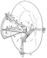
- the present invention provides a second embodiment shown in the single figure.
- the tool 1 is mounted on the volume antenna 2.
- the tool 1 comprises on the one hand a support 3 - 5 and on the other hand a pendulum weighing 9 - 12.
- the heavy pendulum is fixed to the support.
- the support is substantially produced in a single geometric plane: the plane of the edges of the antenna 3 - 5. It has three arms, for example at 120 ° from one another .
- Each arm carries a means of attachment to the antenna.
- This fixing means in a first variant consists of a hook 6 - 8 which slides along the arm which carries it.
- the hook 6 can be provided with a locking means such as a pressure screw which fixes its position on the arm.
- the hook is fixed to the end of the arm which comprises a telescopic part which it is possible by well known locking means to fix.
- Such arrangements allow the adaptation of the tool according to the invention to antennas of various openings.
- an angle protractor 9 On one of the arms 5 of the tool is mounted an angle protractor 9.
- An axis 11 is mounted on the arm 5 passing through the center of measurement of the angles of the protractor.
- a mass 12 On this axis 11 is mounted a needle 10 whose axis S B makes it possible to measure the angle of elevation.
- the 0 ° graduation remains permanently parallel to the axis S A of the antenna 2. Reading the position of the needle 10 on the protractor therefore allows a direct reading of the elevation angle.
- a spirit level 13 is also provided, mounted in such a way on the arms 3 and 4 that it remains along a straight line parallel to the axis 11 and perpendicular to the axis SA of the antenna 2.
- Other configurations can be envisaged.
- the antenna is placed at the 0 ° site.
- the antenna exit plane is then horizontal.
- the 0 ° axis, the S A axis and the S B axis must coincide with the vertical of the place.
- Obtaining a horizontal antenna exit plane is obtained when simultaneously the bubble level is stabilized and the axis S B is aligned with the 0 ° axis of the protractor 9.
Landscapes
- Physics & Mathematics (AREA)
- Engineering & Computer Science (AREA)
- General Physics & Mathematics (AREA)
- Radar, Positioning & Navigation (AREA)
- Remote Sensing (AREA)
- Variable-Direction Aerials And Aerial Arrays (AREA)
- Length-Measuring Instruments Using Mechanical Means (AREA)
Abstract
Description
- La présente invention concerne un outil de mesure de l'angle de site d'une antenne volumique notamment pour ondes hertziennes.
- La présente invention trouve application dans le domaine du matériel grand public de réception d'émissions de télévision par satellite géostationnaire. De telles émissions émises ou réémises par le moyen d'un satellite géostationnaire doivent être captées par des antennes volumiques généralement de forme parabolique. Le pointage de l'antenne sur le satellite doit être réalisé avec une précision en site et en azimut de l'ordre du degré d'arc. Pour permettre une grande diffusion de ce matériel, il est nécessaire d'utiliser des constituants peu coûteux et d'une utilisation simple.
- La présente invention propose un nouveau moyen de réglage de l'un des deux angles en proposant un outil de mesure de l'angle de site d'une antenne volumique pour ondes hertziennes qui comporte un pendule pesant monté sur l'antenne qui coopère avec un moyen de repérage de la position stable du pendule pour permettre de mesurer l'angle de site-de l'antenne.
- La présente invention sera mieux comprise à l'aide de la description et de la figure unique annexée.
- L'idée de base de l'invention est de mesurer l'angle de site dans le plan azimutal qui contient la verticale du lieu en mesurant la position stable d'un pendule pesant mis en mouvement dans ce plan azimutal. Deux modes principaux de réalisation sont proposés ci-après sans pour autant que la présente invention soit limitée à ceux- ci.
- Dans un premier mode de réalisation, l'outil de mesure de l'angle de site de l'antenne volumique comporte un pendule pesant constitué par une simple bille destinée à rouler sur une partie concave de l'antenne volumique. L'antenne comporte une série de -graduations, qui permettent de lire directement la valeur de l'angle de site quand la bille prend sa position stable. Les graduations dans le cas d'une antenne de révolution, sont constituées par exemple par des cercles tracés à l'intérieur du volume de l'antenne avec des repères en degré d'arc. On peut ainsi obtenir une très bonne précision inférieure au degré d'arc dans la mesure de l'angle de site. La rusticité des moyens utilisés peut être une contrepartie avantageuse à l'obligation de graver ou d'imprimer à la fabrication des graduations dont la précision détermine la précision de l'outil de mesure.
- Pour remédier à cet inconvénient, la présente invention propose un deuxième mode de réalisation représenté à la figure unique. L'outil 1 est monté sur l'antenne volumique 2. L'outil 1 comporte d'une part un support 3 - 5 et d'autre part un pendule pesant 9 - 12. Le pendule pesant est fixé au support. Dans une variante particulièrement adaptée aux antennes de révolution, le support est sensiblement réalisé dans un plan géométrique unique : le plan des bords de l'antenne 3 - 5. Il comporte trois bras, par exemple à 120 ° l'un de l'autre. Chaque bras porte un moyen de fixation à l'antenne. Ce moyen de fixation dans une première variante est constitué par un crochet 6 - 8 qui coulisse le long du bras qui le porte. Le crochet 6 peut être muni d'un moyen de blocage comme une vis de pression qui fixe sa position sur le bras. Dans une seconde variante, le crochet est fixé à l'extrémité du bras qui comporte une partie télescopique qu'il est possible par des moyens de blocage bien connus de fixer. De telles dispositions permettent l'adaptation de l'outil selon l'invention à des antennes d'ouvertures variées.
- Sur l'un des bras 5 de l'outil, est monté un rapporteur d'angle 9. Un axe 11 est monté sur le bras 5 passant par le centre de mesure des angles du rapporteur. Sur cet axe 11 est monté une masse 12 porteuse d'une aiguille 10 dont l'axe S B permet de mesurer l'angle de site. La graduation 0 ° reste en permanence parallèle à l'axe S A de l'antenne 2. La lecture de la position de l'aiguille 10 sur le rapporteur permet donc une lecture directe de l'angle de site.
- Afin de garantir un étalonnage de l'outil, dans une variante de réalisation il est proposé de monter la tôle 9 du rapporteur d'angle pivotante autour de l'axe 11 grâce à une lumière 16 percée sur la tôle 9 près du bras 5. Le bras 5 porte alors un ensemble vis - écrou qui passe à travers la lumière 16 permettant le blocage de la position du rapporteur. Pour permettre l'étalonnage de l'outil, il est aussi prévu un niveau à bulle 13 monté de telle manière sur les bras 3 et 4 qu'il demeure le long d'une droite parallèle à l'axe 11 et perpendiculaire à l'axe S A de l'antenne 2. D'autres configurations peuvent être envisagées.
- Pour permettre l'étalonnage, on place l'antenne au site 0 °. Le plan de sortie de l'antenne est alors horizontal. L'axe 0 °, l'axe S A et l'axe S B doivent coïncider avec la verticale du lieu. On peut alors régler l'axe 0 ° par le moyen de la lumière 16 pour obtenir un étalonnage convenable. L'obtention d'un plan de sortie d'antenne horizontale est obtenue quand simultanément le niveau à bulle est stabilisé et l'axe S B est aligné avec l'axe 0 ° du rapporteur 9.
Claims (10)
Applications Claiming Priority (2)
| Application Number | Priority Date | Filing Date | Title |
|---|---|---|---|
| FR8305941 | 1983-04-12 | ||
| FR8305941A FR2544486B1 (fr) | 1983-04-12 | 1983-04-12 | Outil de mesure de l'angle de site d'une antenne volumique |
Publications (2)
| Publication Number | Publication Date |
|---|---|
| EP0128053A1 true EP0128053A1 (fr) | 1984-12-12 |
| EP0128053B1 EP0128053B1 (fr) | 1988-03-30 |
Family
ID=9287757
Family Applications (1)
| Application Number | Title | Priority Date | Filing Date |
|---|---|---|---|
| EP19840400684 Expired EP0128053B1 (fr) | 1983-04-12 | 1984-04-06 | Outil de mesure de l'angle de site d'une antenne volumique |
Country Status (4)
| Country | Link |
|---|---|
| EP (1) | EP0128053B1 (fr) |
| AU (1) | AU575559B2 (fr) |
| DE (1) | DE3470215D1 (fr) |
| FR (1) | FR2544486B1 (fr) |
Cited By (4)
| Publication number | Priority date | Publication date | Assignee | Title |
|---|---|---|---|---|
| EP0330465A1 (fr) * | 1988-02-23 | 1989-08-30 | John George Pax Weatherlake | Dispositif d'indication des directions d'azimuth et d'inclinaison |
| CN107576303A (zh) * | 2017-09-26 | 2018-01-12 | 张广河 | 远距离测量天线角度的装置 |
| CN112113539A (zh) * | 2020-09-18 | 2020-12-22 | 国网辽宁省电力有限公司经济技术研究院 | 一种杆塔倾斜监测装置及其监测方法 |
| CN116045895A (zh) * | 2022-09-08 | 2023-05-02 | 中电科普天科技股份有限公司 | 一种射灯天线工况参数测量系统 |
Citations (4)
| Publication number | Priority date | Publication date | Assignee | Title |
|---|---|---|---|---|
| GB132637A (fr) * | 1900-01-01 | |||
| CH192615A (de) * | 1937-01-08 | 1937-08-31 | Samuel Aegerter August | Neigungsmesser mit pendelnd gelagertem Anzeigeglied. |
| US2183902A (en) * | 1939-04-25 | 1939-12-19 | Alexander Spangler Linton | Pitch determining device |
| EP0026001A1 (fr) * | 1979-09-25 | 1981-04-01 | Siemens Aktiengesellschaft | Antenne pour la réception directe des émissions de satellites |
Family Cites Families (1)
| Publication number | Priority date | Publication date | Assignee | Title |
|---|---|---|---|---|
| JPS55149581A (en) * | 1979-05-10 | 1980-11-20 | Sony Corp | Recording and reproducing unit |
-
1983
- 1983-04-12 FR FR8305941A patent/FR2544486B1/fr not_active Expired
-
1984
- 1984-04-06 EP EP19840400684 patent/EP0128053B1/fr not_active Expired
- 1984-04-06 DE DE8484400684T patent/DE3470215D1/de not_active Expired
- 1984-04-11 AU AU26740/84A patent/AU575559B2/en not_active Ceased
Patent Citations (4)
| Publication number | Priority date | Publication date | Assignee | Title |
|---|---|---|---|---|
| GB132637A (fr) * | 1900-01-01 | |||
| CH192615A (de) * | 1937-01-08 | 1937-08-31 | Samuel Aegerter August | Neigungsmesser mit pendelnd gelagertem Anzeigeglied. |
| US2183902A (en) * | 1939-04-25 | 1939-12-19 | Alexander Spangler Linton | Pitch determining device |
| EP0026001A1 (fr) * | 1979-09-25 | 1981-04-01 | Siemens Aktiengesellschaft | Antenne pour la réception directe des émissions de satellites |
Non-Patent Citations (1)
| Title |
|---|
| PATENTS ABSTRACTS OF JAPAN, vol. 6, no. 151 (E-124)[1029], 11 août 1982; & JP-A-57 073 502 (MITSUBISHI DENKI K.K.) 08-05-1982 * |
Cited By (4)
| Publication number | Priority date | Publication date | Assignee | Title |
|---|---|---|---|---|
| EP0330465A1 (fr) * | 1988-02-23 | 1989-08-30 | John George Pax Weatherlake | Dispositif d'indication des directions d'azimuth et d'inclinaison |
| CN107576303A (zh) * | 2017-09-26 | 2018-01-12 | 张广河 | 远距离测量天线角度的装置 |
| CN112113539A (zh) * | 2020-09-18 | 2020-12-22 | 国网辽宁省电力有限公司经济技术研究院 | 一种杆塔倾斜监测装置及其监测方法 |
| CN116045895A (zh) * | 2022-09-08 | 2023-05-02 | 中电科普天科技股份有限公司 | 一种射灯天线工况参数测量系统 |
Also Published As
| Publication number | Publication date |
|---|---|
| DE3470215D1 (en) | 1988-05-05 |
| AU2674084A (en) | 1984-10-18 |
| FR2544486A1 (fr) | 1984-10-19 |
| EP0128053B1 (fr) | 1988-03-30 |
| AU575559B2 (en) | 1988-08-04 |
| FR2544486B1 (fr) | 1985-06-14 |
Similar Documents
| Publication | Publication Date | Title |
|---|---|---|
| US5842282A (en) | Laser angle adjustment device for laser measuring instruments | |
| FR2530334A1 (fr) | Jauge d'alignement pour antenne en forme de cuvette | |
| US6697026B1 (en) | Satellite antenna alignment device | |
| US6487783B1 (en) | Laser guided chalk line apparatus | |
| BE898730A (fr) | Perfectionnements au pointage d'un canon. | |
| EP0128053B1 (fr) | Outil de mesure de l'angle de site d'une antenne volumique | |
| US4356637A (en) | Device for holding a surveyor's range pole | |
| US4999921A (en) | Adjustable spirit level | |
| US20050151035A1 (en) | Multiple function geomatics pole support device | |
| US6481686B1 (en) | Multifunctional turntable for a leveling device | |
| EP0007831A1 (fr) | Dispositif pour le réglage d'orientation en azimut et en site d'un réflecteur d'ondes | |
| JP3679732B2 (ja) | プリズムホルダー | |
| FR2776376A1 (fr) | Appareil pour mesurer de maniere precise et directe l'inclinaison d'un plan par rapport a un autre plan | |
| JPS6336289Y2 (fr) | ||
| FR3133231A1 (fr) | Instrument de mesure configuré pour déterminer des coordonnées d’un point d’intérêt | |
| FR3163153A1 (fr) | Compas solaire. | |
| JPH10141946A (ja) | セオドライト対向ミラー及び指向角測定方法 | |
| EP0743503A2 (fr) | Système de règles-étalon et son utilisation pour l'étalonnage d'un système de mesure de précision | |
| JPH07146140A (ja) | 勾配測定装置 | |
| US20120013963A1 (en) | Holder for a holographic grating | |
| SU1006905A1 (ru) | Прибор дл измерени углов заточки режущего инструмента | |
| FR2540295A1 (fr) | Dispositif de mesure de l'angle de site d'une antenne volumique orientable | |
| GB2272052A (en) | Pendulum level or clinometer | |
| FR2835605A1 (fr) | Dispositif de mesure de pentes adaptable sur un support rectiligne | |
| FR2734354A1 (fr) | Systeme de mesure de longueur de precision |
Legal Events
| Date | Code | Title | Description |
|---|---|---|---|
| PUAI | Public reference made under article 153(3) epc to a published international application that has entered the european phase |
Free format text: ORIGINAL CODE: 0009012 |
|
| AK | Designated contracting states |
Designated state(s): DE GB |
|
| 17P | Request for examination filed |
Effective date: 19850522 |
|
| RAP1 | Party data changed (applicant data changed or rights of an application transferred) |
Owner name: SOCIETE ELECTRONIQUE DE LA REGION PAYS DE LOIRE |
|
| 17Q | First examination report despatched |
Effective date: 19860724 |
|
| GRAA | (expected) grant |
Free format text: ORIGINAL CODE: 0009210 |
|
| AK | Designated contracting states |
Kind code of ref document: B1 Designated state(s): DE GB |
|
| REF | Corresponds to: |
Ref document number: 3470215 Country of ref document: DE Date of ref document: 19880505 |
|
| GBT | Gb: translation of ep patent filed (gb section 77(6)(a)/1977) | ||
| PLBE | No opposition filed within time limit |
Free format text: ORIGINAL CODE: 0009261 |
|
| STAA | Information on the status of an ep patent application or granted ep patent |
Free format text: STATUS: NO OPPOSITION FILED WITHIN TIME LIMIT |
|
| 26N | No opposition filed | ||
| PG25 | Lapsed in a contracting state [announced via postgrant information from national office to epo] |
Ref country code: GB Effective date: 19890406 |
|
| GBPC | Gb: european patent ceased through non-payment of renewal fee | ||
| PG25 | Lapsed in a contracting state [announced via postgrant information from national office to epo] |
Ref country code: DE Effective date: 19900103 |