EP0128083A1 - Vorrichtung zum Entkoppeln der Sternradzuführung für Munition in automatischen Feuerwaffen - Google Patents
Vorrichtung zum Entkoppeln der Sternradzuführung für Munition in automatischen Feuerwaffen Download PDFInfo
- Publication number
- EP0128083A1 EP0128083A1 EP84401069A EP84401069A EP0128083A1 EP 0128083 A1 EP0128083 A1 EP 0128083A1 EP 84401069 A EP84401069 A EP 84401069A EP 84401069 A EP84401069 A EP 84401069A EP 0128083 A1 EP0128083 A1 EP 0128083A1
- Authority
- EP
- European Patent Office
- Prior art keywords
- control shaft
- operating member
- rocker
- rotation
- line
- Prior art date
- Legal status (The legal status is an assumption and is not a legal conclusion. Google has not performed a legal analysis and makes no representation as to the accuracy of the status listed.)
- Withdrawn
Links
Images

Classifications
-
- F—MECHANICAL ENGINEERING; LIGHTING; HEATING; WEAPONS; BLASTING
- F41—WEAPONS
- F41A—FUNCTIONAL FEATURES OR DETAILS COMMON TO BOTH SMALLARMS AND ORDNANCE, e.g. CANNONS; MOUNTINGS FOR SMALLARMS OR ORDNANCE
- F41A9/00—Feeding or loading of ammunition; Magazines; Guiding means for the extracting of cartridges
- F41A9/49—Internally-powered drives, i.e. operated by propellant charge energy, e.g. couplings, clutches, energy accumulators
-
- F—MECHANICAL ENGINEERING; LIGHTING; HEATING; WEAPONS; BLASTING
- F16—ENGINEERING ELEMENTS AND UNITS; GENERAL MEASURES FOR PRODUCING AND MAINTAINING EFFECTIVE FUNCTIONING OF MACHINES OR INSTALLATIONS; THERMAL INSULATION IN GENERAL
- F16D—COUPLINGS FOR TRANSMITTING ROTATION; CLUTCHES; BRAKES
- F16D11/00—Clutches in which the members have interengaging parts
- F16D11/08—Clutches in which the members have interengaging parts actuated by moving a non-rotating part axially
- F16D11/10—Clutches in which the members have interengaging parts actuated by moving a non-rotating part axially with clutching members movable only axially
Definitions
- the present invention relates to systems for supplying ammunition to automatic weapons, and more particularly to a device making it possible to dissociate them from their training system.
- the outfitters with rotor that is to say with star wheels, also called star feed lines, are intended to supply an automatic weapon with ammunition assembled in bands using links and hooks. They include an extraction station in which the strip of ammunition scrolls under the action of a central rotor with star wheels, and where each ammunition, enclosed by a link, is extracted from it to be conveyed to a position waiting or towards an insertion position in the weapon.
- star feeding systems for automatic weapons of any caliber and more particularly of a caliber of 15 to 40 mm.
- supply lines of this kind are actuated in rotation by a control shaft, itself driven by a motor shaft is connected to a motorization external to the weapon, which for example, also causes the reciprocating movement of the cylinder head, or driven by borrowing gas.
- a dog coupling device between the star supply line and its drive shaft.
- This device has three positions: in the clutch position, the star line is driven in rotation, in the intermediate position, the star line is crazy, while in the clutch position, it is locked to the breech box of the weapon and therefore immobilized in rotation.
- the invention proposes to remedy these drawbacks by proposing a simple and reliable clutch and clutch clutch device which makes it possible both to interrupt the connection with the motorization of the power star line and to rotate at will. this line back and forth.
- the subject of the invention is therefore a declutching device for a line of feed stars for automatic weapon ammunition, this feed line being actuated in rotation by a control shaft driven by a motor shaft, device characterized in that that it comprises a removable operating member for on the one hand, actuating the declutching of the control shaft with the motor shaft, and on the other hand, rotating the control shaft alone.
- the operating member is integral with the control shaft of the star line in the declutched position, in order to ensure security of operation.
- the invention also relates to a device as described above, characterized in that it comprises at least one rocker rocker pivoting about an axis orthogonal to the axis of the control shaft, the rocker arm being linked in rotation on the one hand to this shaft, and, on the other hand, in the clutch position, linked in rotation to a drive means, actuated by the drive shaft, mounted freely and coaxially on the control shaft and secured in translation thereof, the rocker arm having a projection on which the operating member comes to bear, the latter having at least one connection means in rotation with the control shaft.
- the operating member has a notch cooperating with the projection of the rocker arm to secure the rocker arm and the operating member in the declutched position of the rocker arm.
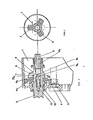
- FIG. 1 shows in a known manner a motor pinion 4 which rotates the shaft 5 for controlling a line of star feeds of ammunition, not shown.
- the driving pinion is for example actuated by a motor external to the weapon and integral in rotation with a drum causing the reciprocating rectilinear movement of the breech.
- the movement of the shaft 5 on the pinion 4 driven by the pinion 3 is effected by a clutch system having three rockers arranged at 120 ° around the shaft 5 (see FIG. 3).
- the number of rocker arms is in principle equal to the number of branches of the stars in the supply line, but may be different depending on the reduction ratio applied to the rotation of the control shaft of the star line.
- a rocker arm 6 is mounted tilting about an axis 7 orthogonal to the axis of the shaft 5, fixed on a yoke of the rear end 8 of the shaft 5 and is therefore linked in rotation to this shaft.
- This rocker arm is provided with a spring 6a engaging in a housing 4a formed on the rear surface of the pinion 4.
- the pinion 4 is mounted free and coaxial on the shaft. 5, but is integral in translation with the latter.
- the rocker In its internal part close to the axis of the shaft 5, the rocker has a projection 6b on which comes to bear the end of an operating member 9, for, in the declutched position ( Figure 2), tilt the rocker arm against the restoring force that a spring 10 housed coaxially in the shaft 5 applies to a coaxial rod 11 forming a stop for the rocker arm in the clutch position (FIG. 1).
- the tip of the operating member which is presented in the form of a removable key or crank, has a notch 9a of shape complementary to that of the projection 6b of the rocker arm so as to secure the latter and the operating member in the declutched position of the rocker arm (FIG. 2).
- the cylindrical end of the operating member has longitudinal flats or grooves 9b for its connection in rotation with the control shaft on the rear end of which the corresponding flats or grooves are formed in a longitudinal housing 12 where it comes engage the operating device.
- the servant of the weapon wants to disengage the continuous rotation of the line of feeding stars, either to modify the type of the ammunition supplied, therefore to release the last ammunition in strip in the food store and introduce a new strip or in case of an operating incident, or even at the beginning of operation, upon introduction of an ammunition belt, it engages the operating member through the opening practiced e in the rear housing at a rear bearing supporting the star line control shaft.
- the tip of the operating member abuts at the bottom of the cylindrical housing formed in the shaft to simultaneously cause the rocker arms to tilt and push the action of the return spring of these rocker arms into the clutched position.
- the control shaft is no longer linked in rotation to the drive pinion, it can then be manually actuated in rotation in both directions to carry out the operations mentioned above.
- the operating position corresponding to the endpiece engaged to the end of its travel, can be identified by an external index.
Landscapes
- Engineering & Computer Science (AREA)
- General Engineering & Computer Science (AREA)
- Mechanical Engineering (AREA)
- Transmission Devices (AREA)
Applications Claiming Priority (2)
| Application Number | Priority Date | Filing Date | Title |
|---|---|---|---|
| FR8309219A FR2547043A1 (fr) | 1983-06-03 | 1983-06-03 | Dispositif de decrabotage pour ligne d'etoiles d'alimentation en munitions d'armes automatiques |
| FR8309219 | 1983-06-03 |
Publications (1)
| Publication Number | Publication Date |
|---|---|
| EP0128083A1 true EP0128083A1 (de) | 1984-12-12 |
Family
ID=9289449
Family Applications (1)
| Application Number | Title | Priority Date | Filing Date |
|---|---|---|---|
| EP84401069A Withdrawn EP0128083A1 (de) | 1983-06-03 | 1984-05-24 | Vorrichtung zum Entkoppeln der Sternradzuführung für Munition in automatischen Feuerwaffen |
Country Status (2)
| Country | Link |
|---|---|
| EP (1) | EP0128083A1 (de) |
| FR (1) | FR2547043A1 (de) |
Citations (5)
| Publication number | Priority date | Publication date | Assignee | Title |
|---|---|---|---|---|
| BE543359A (de) * | ||||
| US1798047A (en) * | 1928-04-10 | 1931-03-24 | Florian H Ubrich | Clutch |
| GB712867A (en) * | 1951-03-27 | 1954-08-04 | Brevets Aero Mecaniques | Improvements in belt feed mechanisms for automatic firearms |
| BE677263A (de) * | 1965-03-02 | 1966-08-01 | ||
| DE2430002A1 (de) * | 1974-06-22 | 1976-01-08 | Wegmann & Co | Gurtwechseleinrichtung fuer schnellfeuerwaffen |
-
1983
- 1983-06-03 FR FR8309219A patent/FR2547043A1/fr active Pending
-
1984
- 1984-05-24 EP EP84401069A patent/EP0128083A1/de not_active Withdrawn
Patent Citations (5)
| Publication number | Priority date | Publication date | Assignee | Title |
|---|---|---|---|---|
| BE543359A (de) * | ||||
| US1798047A (en) * | 1928-04-10 | 1931-03-24 | Florian H Ubrich | Clutch |
| GB712867A (en) * | 1951-03-27 | 1954-08-04 | Brevets Aero Mecaniques | Improvements in belt feed mechanisms for automatic firearms |
| BE677263A (de) * | 1965-03-02 | 1966-08-01 | ||
| DE2430002A1 (de) * | 1974-06-22 | 1976-01-08 | Wegmann & Co | Gurtwechseleinrichtung fuer schnellfeuerwaffen |
Also Published As
| Publication number | Publication date |
|---|---|
| FR2547043A1 (fr) | 1984-12-07 |
Similar Documents
| Publication | Publication Date | Title |
|---|---|---|
| EP0322265B1 (de) | Kupplungssteuereinrichtung, insbesondere für Kraftfahrzeuge | |
| FR2549553A1 (fr) | Embrayage pour vehicule de travail tel que motoculteur | |
| WO2014106714A1 (fr) | Boîte de vitesses pour engin automoteur, tel que tondeuse à gazon | |
| FR2733040A1 (fr) | Arme automatique avec un tube d'arme interchangeable | |
| EP0200584B1 (de) | Fremdangetriebene automatische Waffe | |
| FR2538528A1 (fr) | Conteneur pour la reception et l'amenee de projectiles dans la tourelle d'un char d'assaut | |
| EP0571285B1 (de) | Automatische Waffe mit einer kippbaren Patronenkammer zum Abschiessen von teleskopischen zylindrischen Munitionen | |
| EP0128083A1 (de) | Vorrichtung zum Entkoppeln der Sternradzuführung für Munition in automatischen Feuerwaffen | |
| EP0459851A1 (de) | Elektromechanisches Programmschaltwerk mit leichter Programmvorwahl | |
| EP0129457B1 (de) | Beidseitige Munitionszuführung für automatische Feuerwaffen | |
| BE506568A (fr) | Dispositif pour armes a feu automatiques a tambour revolver | |
| CH172805A (fr) | Mécanisme pour le déclenchement d'un organe mobile soumis à une force de rappel élevée. | |
| EP1412651B1 (de) | Verbindungsvorrichtung für kupplungsmuffe | |
| EP0553033B1 (de) | Befestigungs- und Verbindungsteil, insbesondere für eine Lichtverstärkereinheit für eine Bilderzeugungsvorrichtung in einem Pilotenhelm | |
| FR2759119A1 (fr) | Demarreur de vehicule automobile comportant un lanceur perfectionne | |
| EP0117773B1 (de) | Fremdangetriebene Ladetrommel für Kanonen | |
| EP0153242B1 (de) | Automatische Ladevorrichtung für Kanonen | |
| EP0531595A1 (de) | Sicherheitsvorrichtung für automatische Feuerwaffen | |
| EP0012046A1 (de) | Elektrischer Anlasser für Brennkraftmaschinen, insbesondere für Kraftfahrzeuge | |
| FR2925149A1 (fr) | Magasin d'alimentation semi-automatique en munitions d'une arme | |
| FR2485128A1 (fr) | Embrayage et dispositif de condamnation electrique centralisee des serrures d'un vehicule automobile mettant en oeuvre ledit embrayage | |
| EP0599683A1 (de) | Verfahren zum Laden von Munition in einem schwenkbaren Patronenlager, und Anordnung zur Anwendung | |
| EP0467816B1 (de) | Vorrichtung zur Entfernung von Fasern und textilem Flug | |
| FR2464451A1 (fr) | Nouveau dispositif d'alimentation automatique en etoupilles d'un canon d'artillerie | |
| FR2764685A1 (fr) | Dispositif de declenchement electrique du tir pour une arme a feu individuelle de petit ou moyen calibre |
Legal Events
| Date | Code | Title | Description |
|---|---|---|---|
| PUAI | Public reference made under article 153(3) epc to a published international application that has entered the european phase |
Free format text: ORIGINAL CODE: 0009012 |
|
| 17P | Request for examination filed |
Effective date: 19840613 |
|
| AK | Designated contracting states |
Designated state(s): BE CH DE GB LI |
|
| STAA | Information on the status of an ep patent application or granted ep patent |
Free format text: STATUS: THE APPLICATION HAS BEEN WITHDRAWN |
|
| 18W | Application withdrawn |
Withdrawal date: 19860303 |
|
| RIN1 | Information on inventor provided before grant (corrected) |
Inventor name: FOUGEROUX, THIERRY Inventor name: ROCHELLE, MARC |