EP0128199B1 - Kühlsystem mit zwischenraumdichtungen - Google Patents
Kühlsystem mit zwischenraumdichtungen Download PDFInfo
- Publication number
- EP0128199B1 EP0128199B1 EP84900228A EP84900228A EP0128199B1 EP 0128199 B1 EP0128199 B1 EP 0128199B1 EP 84900228 A EP84900228 A EP 84900228A EP 84900228 A EP84900228 A EP 84900228A EP 0128199 B1 EP0128199 B1 EP 0128199B1
- Authority
- EP
- European Patent Office
- Prior art keywords
- displacer
- refrigerator
- drive means
- gas
- electrically powered
- Prior art date
- Legal status (The legal status is an assumption and is not a legal conclusion. Google has not performed a legal analysis and makes no representation as to the accuracy of the status listed.)
- Expired
Links
- 238000005057 refrigeration Methods 0.000 title description 8
- 239000012530 fluid Substances 0.000 claims description 8
- 238000009966 trimming Methods 0.000 abstract description 5
- 239000007789 gas Substances 0.000 description 30
- 239000011195 cermet Substances 0.000 description 11
- 230000005355 Hall effect Effects 0.000 description 9
- 230000009471 action Effects 0.000 description 5
- 238000010586 diagram Methods 0.000 description 5
- 239000001307 helium Substances 0.000 description 5
- 229910052734 helium Inorganic materials 0.000 description 5
- SWQJXJOGLNCZEY-UHFFFAOYSA-N helium atom Chemical compound [He] SWQJXJOGLNCZEY-UHFFFAOYSA-N 0.000 description 5
- 230000000979 retarding effect Effects 0.000 description 5
- 230000008859 change Effects 0.000 description 3
- 238000001816 cooling Methods 0.000 description 3
- 230000003247 decreasing effect Effects 0.000 description 3
- 230000001419 dependent effect Effects 0.000 description 3
- 230000004907 flux Effects 0.000 description 3
- 238000007789 sealing Methods 0.000 description 3
- 239000004593 Epoxy Substances 0.000 description 2
- XEEYBQQBJWHFJM-UHFFFAOYSA-N Iron Chemical compound [Fe] XEEYBQQBJWHFJM-UHFFFAOYSA-N 0.000 description 2
- PXHVJJICTQNCMI-UHFFFAOYSA-N Nickel Chemical compound [Ni] PXHVJJICTQNCMI-UHFFFAOYSA-N 0.000 description 2
- 239000003990 capacitor Substances 0.000 description 2
- 230000006835 compression Effects 0.000 description 2
- 238000007906 compression Methods 0.000 description 2
- 239000011159 matrix material Substances 0.000 description 2
- 230000010363 phase shift Effects 0.000 description 2
- 230000002265 prevention Effects 0.000 description 2
- 230000001172 regenerating effect Effects 0.000 description 2
- 240000002791 Brassica napus Species 0.000 description 1
- 229910052785 arsenic Inorganic materials 0.000 description 1
- 238000011109 contamination Methods 0.000 description 1
- 230000005284 excitation Effects 0.000 description 1
- 239000011152 fibreglass Substances 0.000 description 1
- 229910052742 iron Inorganic materials 0.000 description 1
- 239000000463 material Substances 0.000 description 1
- 230000007246 mechanism Effects 0.000 description 1
- 229910052751 metal Inorganic materials 0.000 description 1
- 239000002184 metal Substances 0.000 description 1
- 230000004048 modification Effects 0.000 description 1
- 238000012986 modification Methods 0.000 description 1
- 229910052759 nickel Inorganic materials 0.000 description 1
- 229910000938 samarium–cobalt magnet Inorganic materials 0.000 description 1
Images


Classifications
-
- F—MECHANICAL ENGINEERING; LIGHTING; HEATING; WEAPONS; BLASTING
- F25—REFRIGERATION OR COOLING; COMBINED HEATING AND REFRIGERATION SYSTEMS; HEAT PUMP SYSTEMS; MANUFACTURE OR STORAGE OF ICE; LIQUEFACTION SOLIDIFICATION OF GASES
- F25B—REFRIGERATION MACHINES, PLANTS OR SYSTEMS; COMBINED HEATING AND REFRIGERATION SYSTEMS; HEAT PUMP SYSTEMS
- F25B9/00—Compression machines, plants or systems, in which the refrigerant is air or other gas of low boiling point
- F25B9/14—Compression machines, plants or systems, in which the refrigerant is air or other gas of low boiling point characterised by the cycle used, e.g. Stirling cycle
-
- F—MECHANICAL ENGINEERING; LIGHTING; HEATING; WEAPONS; BLASTING
- F01—MACHINES OR ENGINES IN GENERAL; ENGINE PLANTS IN GENERAL; STEAM ENGINES
- F01B—MACHINES OR ENGINES, IN GENERAL OR OF POSITIVE-DISPLACEMENT TYPE, e.g. STEAM ENGINES
- F01B11/00—Reciprocating-piston machines or engines without rotary main shaft, e.g. of free-piston type
- F01B11/02—Equalising or cushioning devices
-
- F—MECHANICAL ENGINEERING; LIGHTING; HEATING; WEAPONS; BLASTING
- F02—COMBUSTION ENGINES; HOT-GAS OR COMBUSTION-PRODUCT ENGINE PLANTS
- F02G—HOT GAS OR COMBUSTION-PRODUCT POSITIVE-DISPLACEMENT ENGINE PLANTS; USE OF WASTE HEAT OF COMBUSTION ENGINES; NOT OTHERWISE PROVIDED FOR
- F02G1/00—Hot gas positive-displacement engine plants
- F02G1/04—Hot gas positive-displacement engine plants of closed-cycle type
- F02G1/043—Hot gas positive-displacement engine plants of closed-cycle type the engine being operated by expansion and contraction of a mass of working gas which is heated and cooled in one of a plurality of constantly communicating expansible chambers, e.g. Stirling cycle type engines
- F02G1/0435—Hot gas positive-displacement engine plants of closed-cycle type the engine being operated by expansion and contraction of a mass of working gas which is heated and cooled in one of a plurality of constantly communicating expansible chambers, e.g. Stirling cycle type engines the engine being of the free piston type
-
- F—MECHANICAL ENGINEERING; LIGHTING; HEATING; WEAPONS; BLASTING
- F02—COMBUSTION ENGINES; HOT-GAS OR COMBUSTION-PRODUCT ENGINE PLANTS
- F02G—HOT GAS OR COMBUSTION-PRODUCT POSITIVE-DISPLACEMENT ENGINE PLANTS; USE OF WASTE HEAT OF COMBUSTION ENGINES; NOT OTHERWISE PROVIDED FOR
- F02G1/00—Hot gas positive-displacement engine plants
- F02G1/04—Hot gas positive-displacement engine plants of closed-cycle type
- F02G1/043—Hot gas positive-displacement engine plants of closed-cycle type the engine being operated by expansion and contraction of a mass of working gas which is heated and cooled in one of a plurality of constantly communicating expansible chambers, e.g. Stirling cycle type engines
- F02G1/044—Hot gas positive-displacement engine plants of closed-cycle type the engine being operated by expansion and contraction of a mass of working gas which is heated and cooled in one of a plurality of constantly communicating expansible chambers, e.g. Stirling cycle type engines having at least two working members, e.g. pistons, delivering power output
- F02G1/0445—Engine plants with combined cycles, e.g. Vuilleumier
-
- F—MECHANICAL ENGINEERING; LIGHTING; HEATING; WEAPONS; BLASTING
- F02—COMBUSTION ENGINES; HOT-GAS OR COMBUSTION-PRODUCT ENGINE PLANTS
- F02G—HOT GAS OR COMBUSTION-PRODUCT POSITIVE-DISPLACEMENT ENGINE PLANTS; USE OF WASTE HEAT OF COMBUSTION ENGINES; NOT OTHERWISE PROVIDED FOR
- F02G1/00—Hot gas positive-displacement engine plants
- F02G1/04—Hot gas positive-displacement engine plants of closed-cycle type
- F02G1/043—Hot gas positive-displacement engine plants of closed-cycle type the engine being operated by expansion and contraction of a mass of working gas which is heated and cooled in one of a plurality of constantly communicating expansible chambers, e.g. Stirling cycle type engines
- F02G1/053—Component parts or details
- F02G1/0535—Seals or sealing arrangements
-
- F—MECHANICAL ENGINEERING; LIGHTING; HEATING; WEAPONS; BLASTING
- F02—COMBUSTION ENGINES; HOT-GAS OR COMBUSTION-PRODUCT ENGINE PLANTS
- F02G—HOT GAS OR COMBUSTION-PRODUCT POSITIVE-DISPLACEMENT ENGINE PLANTS; USE OF WASTE HEAT OF COMBUSTION ENGINES; NOT OTHERWISE PROVIDED FOR
- F02G2250/00—Special cycles or special engines
- F02G2250/18—Vuilleumier cycles
-
- F—MECHANICAL ENGINEERING; LIGHTING; HEATING; WEAPONS; BLASTING
- F25—REFRIGERATION OR COOLING; COMBINED HEATING AND REFRIGERATION SYSTEMS; HEAT PUMP SYSTEMS; MANUFACTURE OR STORAGE OF ICE; LIQUEFACTION SOLIDIFICATION OF GASES
- F25B—REFRIGERATION MACHINES, PLANTS OR SYSTEMS; COMBINED HEATING AND REFRIGERATION SYSTEMS; HEAT PUMP SYSTEMS
- F25B2309/00—Gas cycle refrigeration machines
- F25B2309/001—Gas cycle refrigeration machines with a linear configuration or a linear motor
-
- F—MECHANICAL ENGINEERING; LIGHTING; HEATING; WEAPONS; BLASTING
- F25—REFRIGERATION OR COOLING; COMBINED HEATING AND REFRIGERATION SYSTEMS; HEAT PUMP SYSTEMS; MANUFACTURE OR STORAGE OF ICE; LIQUEFACTION SOLIDIFICATION OF GASES
- F25B—REFRIGERATION MACHINES, PLANTS OR SYSTEMS; COMBINED HEATING AND REFRIGERATION SYSTEMS; HEAT PUMP SYSTEMS
- F25B2309/00—Gas cycle refrigeration machines
- F25B2309/003—Gas cycle refrigeration machines characterised by construction or composition of the regenerator
Definitions
- This invention relates to refrigeration systems which include reciprocating displacers such as split Stirling cryogenic refrigerators.
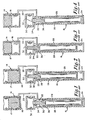
- FIG. 1-4 A conventional split Stirling refrigeration system is shown in Figs. 1-4.
- This system includes a reciprocating compressor 14 and a cold finger 16.
- the piston 17 of the compressor provides a nearly sinusoidal pressure variation in a pressurized refrigeration gas such as helium.
- the pressure variation in a head space 18 is transmitted through a supply line 20 to the cold finger 16.
- the usual split Stirling system includes an electric motor driven compressor. A modification of that system is the split Vuilleumier. In that system a thermal compressor is used. This invention is applicable to both of those refrigerators as well as others.
- a cylindrical displacer 26 is free to move in a reciprocating motion to change the volumes of a warm space 22 and a cold space 24 within the cold finger.
- the displacer 26 contains a regenerative heat exchanger 28 comprised of several hundred fine-mesh metal screen discs stacked to form a cylindrical matrix.
- Other regenerators such as those with stacked balls, are also known.
- Helium is free to flow through the regenerator between the warm space 22 and the cold space 24.
- a piston element 30 extends upwardly from the main body of the displacer 26 into a gas spring volume 32 at the warm end of the cold finger.
- the refrigeration system of Figs. 1-4 can be seen as including two isolated volumes of pressurized gas.
- a working volume of gas comprises the gas in the space 18 at the end of the compressor, the gas in the supply line 20, and the gas in the spaces 22 and 24 and in the regenerator 28 of the cold finger 16.
- the second volume of gas is the gas spring volume 32 which is sealed from the working volume by a piston seal 34 surrounding the drive piston 30.
- the compressor piston 17 With the sinusoidal drive from a crank shaft mechanism, the compressor piston 17 now begins to expand the working volume as shown in Fig. 3. With expansion, the high pressure helium in the cold space 24 is cooled even further. It is this cooling in the cold space 24 which provides the refrigeration for maintaining a temperature gradient of over 200 degrees Kelvin over the length of the regenerator.
- the seals 34 and 36 are designed and fabricated to provide an amount of loading to the displacer to retard the displacer movement by an optimum amount.
- a major problem of split Stirling systems is that with wear of the seals the braking action of those seals varies. As the braking action becomes less the displacer movement is advanced in phase and the efficiency of the refrigerator is decreased. Also, braking action can be dependent on the direction of the pressure differential across the seal.
- the refrigerator In addition to the problem of wear of the seals, the refrigerator is often subjected to different environments. For example, a refrigerator may be stored at extremely high temperature and be called on to provide efficient cyogenic refrigeration. On the other hand, the refrigerator may be subject to very cold environments. The sealing action and friction of the seals is generally very dependent on temperature.
- electromagnetic breaking means may be provided as for example in EP-A-0 037 102 and EP-A-0 043 249.
- a refrigerator has a gas displacer which reciprocates in a cold finger housing to displace gas in a working volume of gas through a regenerator.
- the fluid pressure in the working volume varies between maximum and minimum pressures.
- a spring volume of gas is provided, and a piston element extends axially from the displacer into the spring volume.
- the cross sectional area of the piston element is such that the pressure differential across the piston element, between the working volume and the spring volume, drives the displacer element through a substantially full stroke in each direction as in conventional pneumatically driven Stirling refrigerators.
- an electrically powered linear drive is provided to the displacer, but that drive only applies force to the displacer for trimming the movement of the displacer.
- Such trimming of the movement may include phase control to assure proper synchronization of the displacer movement with the compressor pressure wave, prevention of overstroke in which the displacer raps against one or both ends of the cold finger and assurance of full stroke which might be inhibited by seal friction or the like.
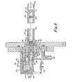
- the cold finger of the split Stirling refrigerator shown in Fig. 5 includes an outer cylindrical casing 50 fixed to and suspended from a cold finger head 52.
- the opposite, cold end of the cylinder 50 is closed by a heat exchanger cap 53.
- An infrared detecting device or the like may be mounted to that heat exchanger.
- a displacer 54, mounted for reciprocating movement within the cylinder 50, includes a fiberglass epoxy cylinder 55.
- the cylinder 55 is packed with nickel balls 56 sandwiched between short stacks of screen 58 at each end of the regenerator.
- the screen is held in place by porous plugs 60 and 61.
- the porous plug 60 is positioned at the end of a bore 66 in a cermet clearance seal element 62.
- the cermet clearance seal element 62 is fixed to the cylinder 55 by epoxy. It is seated within a second cermet clearance seal element 68 to provide a clearance seal 70.
- a pressure equalization groove (not shown) may be provided in the first cermet element 62 to minimize pressure force differentials on the clearance seal element which might tend to bind the displacer.
- the clearance seal 70 is preferably a .00015 inch (.0038 millimeter) gap between the two cermet clearance seal elements. The gap is half the diametrical clearance between the clearance seal elements. That clearance seal allows for virtually dragless movement of the element 62 within the element 68 while providing excellent sealing between the warm end 74 of the cold finger working volume and an annulus 76 between the cold finger cylinder 50 and the displacer cylinder 55.
- the sealing action of the clearance seal is due to the small gap along the approximately .25 inch (6 millimeter) length of the seal.
- Channels 80 are formed in the top of the clearance seal element 68 to provide fluid communication between the warm end 74 of the displacer and an annulus 82.
- the annulus 82 is connected to a compressor (not shown) through a port 86.
- Another outer clearance seal element 88 is positioned within the cold finger head 52. This element is also formed of cermet.
- the clearance seal element 88 has a smaller inner diameter than the element 68 in order to provide a clearance seal 90 with a cermet drive piston 92.
- the cermet piston 92, and thus the cermet of clearance seal element 88 are of nonmagnetic cermet material.
- the clearance seal element 88 is clamped against the cold finger head 52 by a clamping nut 100.
- the piston 92 reciprocates with the main body of the displacer, and in fact the pressure differential across the drive piston serves to drive the entire displacer.
- the piston 92 is joined to the cermet element 62 by means of a pin 96 extending through a transverse slot 98 at the lower end of the piston 92.
- the spring volume 106 is defined in part by a nonmetallic ring 108 which supports two coils 110 and 112 of a linear drive motor.
- the ring 108 isolates the coils from the helium environment of the spring volume 106 to avoid contamination of the helium.
- the spring volume is completed by an end cap 114 joined to a cylindrical housing 116.
- Elastomeric bumpers 124 and 126 are provided to stop overstroke of the magnet; however, overstroke is generally prevented by the linear drive motor as will be discussed below so that bumpers are not required.
- a hall effect position sensor 128 is provided to sense the location of the magnet 118 within the stroke of the magnet, the piston 92 and the displacer 54.
- the primary forces applied to the piston 92 and displacer 55 which result in movement of those elements are the pressure of the spring volume 106 acting against the left end of the drive piston 92 as viewed in Fig. 5, the pressure in the working volume at the warm end 74 acting against the left end of the displacer, the working volume pressure at the cold volume 57 acting against the right end of the displacer, and friction forces.
- clearance seals rather than conventional friction seals, substantially all Coulomb friction forces have been eliminated.
- the force equation for the displacer and drive piston is: where P c , P w and P s are the fluid pressure at the cold end 57, at the warm end 74, and in the spring volume 106, respectively, A c and As are the cross sectional areas of the regenerator cylinder 55 and the piston cylinder 92, respectively, and fc ou; is the Coulomb friction which resists movement of the displacer/piston assembly.
- the cold end pressure term of equation 1 can be replaced as follows:
- Equation 4 there are two terms relating to the retarding forces on the displacer which act against movement of the displacer caused by the difference in working volume and spring volume pressure.
- the second term is a function of the Coulomb friction due to seals or a discrete Coulomb friction braking element.
- the first term is a function of the pressure differential across the regenerative matrix and the areas of the main body of the displacer and of the drive piston.
- the ratio A c /A s is always greater than one and can be selected by setting the diameters of the driven piston and main body of the displacer.
- the differential pressure term of equation (4) can be increased.
- that term can be increased to the extent necessary to account for the entire retarding force needed, and the Coulomb friction term can be decreased to zero. In decreasing the Coulomb friction term to zero, friction seals can be entirely eliminated.
- the linear motor provided in Fig. 5 is for the purpose of merely trimming the motion of the displacer to assure that the displacer makes full strokes without rapping the ends of the cold finger in proper phase with the pressure wave. Because the motor merely provides fine tuning of the displacer movement, primarily at the ends of each stroke, a large linear motor is not required.
- the power requirements of the motor, for a one quarter watt Stirling refrigerator, can be less than one third the power requirements in such a refrigerator in which the linear motor must provide the primary driving force to drive the displacer through its entire stroke.
- the housing for the motor can thus be only a little larger than what is generally required for the spring volume of a refrigerator having no linear motor.
- Fig. 6 is a block diagram of the overall circuitry.
- the signal from the Hall effect sensing element 128 is processed in a conventional Hall effect circuit 130.
- the Hall effect device senses the position of the magnetic armature 118 of the linear motor.
- the signal from the Hall effect device is also responsive to the magnetic flux set up by the stator coils of the motor.
- a signal conditioner 132 removes that portion of the Hall effect signal resulting from the coil flux to provide a true armature position signal on line 134. That signal is further processed in a changing position detector 136 to provide signals which indicate whether the displacer is moving and in which direction it is moving.
- the direction signals are applied along with the position signal to logic circuit 137.
- the logic circuit also receives a signal R representative of the timing of the pressure wave. By adjusting the phase shift of a compressor excitation signal 142 through a phase shift circuit 140, the desired phasing of the displacer movement relative to compressor wave can be established.
- the logic circuit 137 provides either a push signal or a pull signal to a linear motor drive circuit 144. When a push signal is received, the driver circuit energizes the two coils 110 and 112 of the linear motor 146 to push the displacer toward the cold end of the cold finger. When a pull signal is received, the driver circuit drives current through the two coils to pull the displacer back towards the warm end.
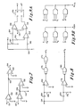
- the signal conditioner 132 is shown in Fig. 7.
- the signal 131 from the Hall effect circuit 130 is amplified in amplifier 148.
- a signal 150 from the linear motor driver circuit 144 is applied through an inverting amplifier 152.
- the signal 150 is indicative of current flow through the motor coils to pull the displacer.
- a signal 154 indicative of whether push current is applied to the motor coils, is applied to the summing node 156 at the input of an inverting amplifier 158.
- the output of that amplifier is applied to a summing node 160 which also receives the amplified Hall effect signal.
- the signal applied to the amplifier 162 is thus the Hall effect signal, compensated for the motor current, to provide a true position signal on line 134.
- the changing position detector is shown in Fig. 8.
- the position signal on line 134 is applied through a differentiating circuit including capacitor 164 and resistor 166 to an amplifier 168 to provide a signal which indicates when the displacer is moving toward the cold end. That signal is squared by a NAND gate 170 and then reinverted by a NAND gate 172.
- the position signal 134 is also applied through another differentiating circuit comprising capacitor 174 and resistor 176 to an amplifier 178 which provides an output which indicates when the displacer is moving toward the warm end. That signal is squared by the NAND gate 180.
- the logic circuitry for controlling the linear motor driver circuit is shown in Figs. 9A and 9B.
- the position signal 134 is compared to reference signals to establish positions of the displacer at which the displacer is to be considered at the ends of its strokes.
- the cold end-end stroke position is determined directly by comparing the position signal on line 134 with a signal derived from a potentiometer 182 through a resistor 184.
- the signals are compared in an amplifier 186.
- a signal is applied by the amplifier 186 to the set input of a flip flop 188 to provide a high output on line P.
- the same signal taken from the potentiometer 182 to determine the cold end end stroke position is applied through a resistor 190 to a comparator 192.
- the other input to that comparator is taken from a potentiometer 194 through a resistor 196.
- the potentiometer 194 sets the point of symmetry, that is the midpoint, between the end stroke positions at the two ends of the stroke.
- the signal from comparator 192 is applied through another comparator 198 in which it is compared with the position signal on line 134.
- the flip flop 188 is reset to provide a high output at the P- line to indicate that the displacer has completed its stroke to the warm end.
- the end position signals P and P-, the direction of movement signals V1 and V2 and the phase shifted signal R are applied to the AND gates of Fig. 9B to provide push and pull signals.
- the reference signal R is timed such that the displacer should be moving toward the cold end or at the cold end so long as that signal is high.
- the displacer should be moving toward the warm end or be at the warm end.
- a push signal is applied.
- the displacer should be moving toward the cold end, has reach the cold end and is continuing toward the cold end (R and P and V1), a a pull signal is applied because the displacer is passing its end stroke position. This signal prevents striking of the displacer at the end of the cold finger.
- the motor drive circuit is shown in Fig. 1.
- the push signal is applied through a resistor 200 to turn on a transistor 202.
- transistor 202 driving current through resistor 204
- transistor 206 is also turned on.
- transistor 212 is turned on.
- current is drawn through the resistor 214 and the motor coil 216. Current through the coil in this direction pushes the displacer toward the cold end. This current is sensed across the resistor 218 at line 154 and a signal applied to the signal conditioner 132 as discussed above.
- transistors 202, 206 and 212 are turned off so that no motor current is applied.
- transistor 222 When a pull signal is applied across resistor 220, transistor 222 is similarly turned on to turn on transistor 224 and, through resistors 226 and 228, to turn on transistor 230. With transistors 224 and 230 conducting, current is drawn through resistor 214 from transistor 230 and directed to the lower end of the coil 216 as viewed in Fig. 10. The current passes through the coil 216 in the pull direction and is then drawn through the transistor 224. As before, the voltage across the resistor 232 provides the pull signal on line 150 which is applied to the signal conditioner 132. Zener diodes 234 and 236 avoid an overvoltage condition across the coil 216.
Landscapes
- Engineering & Computer Science (AREA)
- Mechanical Engineering (AREA)
- General Engineering & Computer Science (AREA)
- Chemical & Material Sciences (AREA)
- Combustion & Propulsion (AREA)
- Physics & Mathematics (AREA)
- Thermal Sciences (AREA)
- Compressors, Vaccum Pumps And Other Relevant Systems (AREA)
- Compressor (AREA)
- Control Of Linear Motors (AREA)
Claims (8)
Applications Claiming Priority (2)
| Application Number | Priority Date | Filing Date | Title |
|---|---|---|---|
| US06/447,192 US4475346A (en) | 1982-12-06 | 1982-12-06 | Refrigeration system with linear motor trimming of displacer movement |
| US447192 | 1982-12-06 |
Publications (2)
| Publication Number | Publication Date |
|---|---|
| EP0128199A1 EP0128199A1 (de) | 1984-12-19 |
| EP0128199B1 true EP0128199B1 (de) | 1988-05-18 |
Family
ID=23775360
Family Applications (1)
| Application Number | Title | Priority Date | Filing Date |
|---|---|---|---|
| EP84900228A Expired EP0128199B1 (de) | 1982-12-06 | 1983-12-05 | Kühlsystem mit zwischenraumdichtungen |
Country Status (6)
| Country | Link |
|---|---|
| US (1) | US4475346A (de) |
| EP (1) | EP0128199B1 (de) |
| JP (1) | JPS59502152A (de) |
| CA (1) | CA1219137A (de) |
| DE (1) | DE3376674D1 (de) |
| WO (1) | WO1984002388A1 (de) |
Families Citing this family (35)
| Publication number | Priority date | Publication date | Assignee | Title |
|---|---|---|---|---|
| US4545209A (en) * | 1983-01-17 | 1985-10-08 | Helix Technology Corporation | Cryogenic refrigeration system with linear drive motors |
| US4698576A (en) * | 1986-06-20 | 1987-10-06 | North American Philips Corporation | Tri-state switching controller for reciprocating linear motors |
| US4711650A (en) * | 1986-09-04 | 1987-12-08 | Raytheon Company | Seal-less cryogenic expander |
| US4870827A (en) * | 1987-08-12 | 1989-10-03 | United Technologies | Hybrid composite compressor |
| US4798054A (en) * | 1987-10-08 | 1989-01-17 | Helix Technology Corporation | Linear drive motor with flexure bearing support |
| US5040372A (en) * | 1990-04-06 | 1991-08-20 | Helix Technology Corporation | Linear drive motor with flexure bearing support |
| US4858442A (en) * | 1988-04-29 | 1989-08-22 | Inframetrics, Incorporated | Miniature integral stirling cryocooler |
| US5056317A (en) * | 1988-04-29 | 1991-10-15 | Stetson Norman B | Miniature integral Stirling cryocooler |
| US4979368A (en) * | 1988-04-29 | 1990-12-25 | Inframetrics, Inc. | Miniature integral stirling cryocooler |
| US5092130A (en) * | 1988-11-09 | 1992-03-03 | Mitsubishi Denki Kabushiki Kaisha | Multi-stage cold accumulation type refrigerator and cooling device including the same |
| GB2279139B (en) * | 1993-06-18 | 1997-12-17 | Mitsubishi Electric Corp | Vuilleumier heat pump |
| US5735127A (en) * | 1995-06-28 | 1998-04-07 | Wisconsin Alumni Research Foundation | Cryogenic cooling apparatus with voltage isolation |
| US6216467B1 (en) | 1998-11-06 | 2001-04-17 | Helix Technology Corporation | Cryogenic refrigerator with a gaseous contaminant removal system |
| US6205792B1 (en) | 1999-10-27 | 2001-03-27 | Maytag Corporation | Refrigerator incorporating stirling cycle cooling and defrosting system |
| EP1467159A4 (de) * | 2001-12-26 | 2006-06-07 | Sharp Kk | Stirlingmotor |
| GB0417610D0 (en) * | 2004-08-06 | 2004-09-08 | Microgen Energy Ltd | A linear free piston stirling machine |
| GB0428057D0 (en) * | 2004-12-22 | 2005-01-26 | Microgen Energy Ltd | A linear free piston stirling machine |
| US7779640B2 (en) * | 2005-09-09 | 2010-08-24 | Raytheon Company | Low vibration cryocooler |
| US7587896B2 (en) * | 2006-05-12 | 2009-09-15 | Flir Systems, Inc. | Cooled infrared sensor assembly with compact configuration |
| US7555908B2 (en) * | 2006-05-12 | 2009-07-07 | Flir Systems, Inc. | Cable drive mechanism for self tuning refrigeration gas expander |
| US8074457B2 (en) * | 2006-05-12 | 2011-12-13 | Flir Systems, Inc. | Folded cryocooler design |
| US8959929B2 (en) * | 2006-05-12 | 2015-02-24 | Flir Systems Inc. | Miniaturized gas refrigeration device with two or more thermal regenerator sections |
| US11047389B2 (en) | 2010-04-16 | 2021-06-29 | Air Squared, Inc. | Multi-stage scroll vacuum pumps and related scroll devices |
| US8910486B2 (en) | 2010-07-22 | 2014-12-16 | Flir Systems, Inc. | Expander for stirling engines and cryogenic coolers |
| US10941762B2 (en) | 2015-01-30 | 2021-03-09 | Wagner Spray Tech Corporation | Piston limit sensing and software control for fluid application |
| US10865793B2 (en) | 2016-12-06 | 2020-12-15 | Air Squared, Inc. | Scroll type device having liquid cooling through idler shafts |
| US12135048B2 (en) | 2017-09-07 | 2024-11-05 | Wagner Spray Tech Corporation | Piston limit sensing for fluid application |
| US20190338989A1 (en) * | 2018-05-01 | 2019-11-07 | Thermolift, Inc. | Linear Actuation System Having Face Coils and Side Coils for Armature Travel Assist |
| EP3788262B1 (de) | 2018-05-04 | 2024-11-20 | Air Squared, Inc. | Flüssigkeitskühlung eines feststehenden und umlaufenden spiralverdichters, expanders oder einer vakuumpumpe |
| US20200025199A1 (en) | 2018-07-17 | 2020-01-23 | Air Squared, Inc. | Dual drive co-rotating spinning scroll compressor or expander |
| US11067080B2 (en) | 2018-07-17 | 2021-07-20 | Air Squared, Inc. | Low cost scroll compressor or vacuum pump |
| US11530703B2 (en) | 2018-07-18 | 2022-12-20 | Air Squared, Inc. | Orbiting scroll device lubrication |
| US11473572B2 (en) | 2019-06-25 | 2022-10-18 | Air Squared, Inc. | Aftercooler for cooling compressed working fluid |
| US11898557B2 (en) | 2020-11-30 | 2024-02-13 | Air Squared, Inc. | Liquid cooling of a scroll type compressor with liquid supply through the crankshaft |
| US11885328B2 (en) | 2021-07-19 | 2024-01-30 | Air Squared, Inc. | Scroll device with an integrated cooling loop |
Family Cites Families (13)
| Publication number | Priority date | Publication date | Assignee | Title |
|---|---|---|---|---|
| FR1407682A (fr) * | 1964-05-22 | 1965-08-06 | Snecma | Perfectionnements aux machines thermiques à pistons libres |
| US3220201A (en) * | 1965-01-25 | 1965-11-30 | Little Inc A | Cryogenic refrigerator operating on the stirling cycle |
| US3548589A (en) * | 1968-01-19 | 1970-12-22 | Atomic Energy Authority Uk | Heat engines |
| US3604821A (en) * | 1969-08-13 | 1971-09-14 | Mc Donnell Douglas Corp | Stirling cycle amplifying machine |
| US3774405A (en) * | 1971-09-09 | 1973-11-27 | Us Air Force | Magnetically driven cryogen vuilleumier refrigerator |
| US3782859A (en) * | 1971-12-07 | 1974-01-01 | M Schuman | Free piston apparatus |
| US3913339A (en) * | 1974-03-04 | 1975-10-21 | Hughes Aircraft Co | Reduction in cooldown time for cryogenic refrigerator |
| US3991586A (en) * | 1975-10-03 | 1976-11-16 | The United States Of America As Represented By The Secretary Of The Army | Solenoid controlled cold head for a cryogenic cooler |
| US4183214A (en) * | 1977-05-05 | 1980-01-15 | Sunpower, Inc. | Spring and resonant system for free-piston Stirling engines |
| IL62493A (en) * | 1980-03-28 | 1984-05-31 | Helix Tech Corp | Refrigeration system with clearance seal and discrete braking element |
| US4397155A (en) * | 1980-06-25 | 1983-08-09 | National Research Development Corporation | Stirling cycle machines |
| FR2510181A1 (fr) * | 1981-07-21 | 1983-01-28 | Bertin & Cie | Convertisseur d'energie thermique en energie electrique a moteur stirling et generateur electrique integre |
| US4389850A (en) * | 1982-04-19 | 1983-06-28 | Cvi Incorporated | Hybrid cryogenic refrigerator |
-
1982
- 1982-12-06 US US06/447,192 patent/US4475346A/en not_active Expired - Fee Related
-
1983
- 1983-12-05 EP EP84900228A patent/EP0128199B1/de not_active Expired
- 1983-12-05 DE DE8484900228T patent/DE3376674D1/de not_active Expired
- 1983-12-05 JP JP84500207A patent/JPS59502152A/ja active Pending
- 1983-12-05 WO PCT/US1983/001893 patent/WO1984002388A1/en not_active Ceased
- 1983-12-06 CA CA000442661A patent/CA1219137A/en not_active Expired
Also Published As
| Publication number | Publication date |
|---|---|
| US4475346A (en) | 1984-10-09 |
| EP0128199A1 (de) | 1984-12-19 |
| WO1984002388A1 (en) | 1984-06-21 |
| CA1219137A (en) | 1987-03-17 |
| DE3376674D1 (en) | 1988-06-23 |
| JPS59502152A (ja) | 1984-12-27 |
Similar Documents
| Publication | Publication Date | Title |
|---|---|---|
| US4475346A (en) | Refrigeration system with linear motor trimming of displacer movement | |
| EP0114069B1 (de) | Mit linearem Antriebsmotor versehenes Tiefkühlsystem | |
| US4578956A (en) | Cryogenic refrigeration system with linear drive motors | |
| US3988901A (en) | Dual loop heat pump system | |
| US4697113A (en) | Magnetically balanced and centered electromagnetic machine and cryogenic refrigerator employing same | |
| US4545738A (en) | Linear motor compressor with clearance seals and gas bearings | |
| US4244192A (en) | Refrigeration system and reciprocating compressor therefor with pressure stabilizing seal | |
| US4761960A (en) | Cryogenic refrigeration system having an involute laminated stator for its linear drive motor | |
| US4514987A (en) | Passive automatic phase delay control of the displacer motion in pneumatically driven split cycle type cryocoolers | |
| US4664685A (en) | Linear drive motor control in a cryogenic refrigerator | |
| US20070295201A1 (en) | Control of Reciprocating Linear Machines | |
| US4024727A (en) | Vuilleumier refrigerator with separate pneumatically operated cold displacer | |
| GB1108097A (en) | Heat energised refrigerator | |
| US4711650A (en) | Seal-less cryogenic expander | |
| US3913339A (en) | Reduction in cooldown time for cryogenic refrigerator | |
| CA1247873A (en) | Linear motor compressor with pressure stabilization ports for use in refrigeration systems | |
| EP0038360B1 (de) | Tieftemtemperatur-apparat | |
| EP0038850B1 (de) | Ventile für tieftemperatur-kühlvorrichtungen | |
| US4543792A (en) | Refrigeration system with clearance seals | |
| US4412423A (en) | Split-cycle cooler with improved pneumatically-driven cooling head | |
| US4798054A (en) | Linear drive motor with flexure bearing support | |
| US5036670A (en) | Cryogenic refrigerator with corner seal | |
| EP0335643B1 (de) | Gaskältemaschine | |
| US4294077A (en) | Cryogenic refrigerator with dual control valves | |
| WO1989003480A3 (en) | Linear motor compressor with stationary piston |
Legal Events
| Date | Code | Title | Description |
|---|---|---|---|
| PUAI | Public reference made under article 153(3) epc to a published international application that has entered the european phase |
Free format text: ORIGINAL CODE: 0009012 |
|
| AK | Designated contracting states |
Designated state(s): CH DE FR GB LI NL |
|
| 17P | Request for examination filed |
Effective date: 19841126 |
|
| 17Q | First examination report despatched |
Effective date: 19860430 |
|
| GRAA | (expected) grant |
Free format text: ORIGINAL CODE: 0009210 |
|
| AK | Designated contracting states |
Kind code of ref document: B1 Designated state(s): CH DE FR GB LI NL |
|
| ET | Fr: translation filed | ||
| REF | Corresponds to: |
Ref document number: 3376674 Country of ref document: DE Date of ref document: 19880623 |
|
| PLBE | No opposition filed within time limit |
Free format text: ORIGINAL CODE: 0009261 |
|
| STAA | Information on the status of an ep patent application or granted ep patent |
Free format text: STATUS: NO OPPOSITION FILED WITHIN TIME LIMIT |
|
| 26N | No opposition filed | ||
| PGFP | Annual fee paid to national office [announced via postgrant information from national office to epo] |
Ref country code: DE Payment date: 19911105 Year of fee payment: 9 |
|
| PGFP | Annual fee paid to national office [announced via postgrant information from national office to epo] |
Ref country code: FR Payment date: 19911115 Year of fee payment: 9 |
|
| PGFP | Annual fee paid to national office [announced via postgrant information from national office to epo] |
Ref country code: GB Payment date: 19911127 Year of fee payment: 9 |
|
| PGFP | Annual fee paid to national office [announced via postgrant information from national office to epo] |
Ref country code: CH Payment date: 19911219 Year of fee payment: 9 |
|
| PGFP | Annual fee paid to national office [announced via postgrant information from national office to epo] |
Ref country code: NL Payment date: 19911231 Year of fee payment: 9 |
|
| PG25 | Lapsed in a contracting state [announced via postgrant information from national office to epo] |
Ref country code: GB Effective date: 19921205 |
|
| PG25 | Lapsed in a contracting state [announced via postgrant information from national office to epo] |
Ref country code: LI Effective date: 19921231 Ref country code: CH Effective date: 19921231 |
|
| PG25 | Lapsed in a contracting state [announced via postgrant information from national office to epo] |
Ref country code: NL Effective date: 19930701 |
|
| GBPC | Gb: european patent ceased through non-payment of renewal fee |
Effective date: 19921205 |
|
| NLV4 | Nl: lapsed or anulled due to non-payment of the annual fee | ||
| PG25 | Lapsed in a contracting state [announced via postgrant information from national office to epo] |
Ref country code: FR Effective date: 19930831 |
|
| REG | Reference to a national code |
Ref country code: CH Ref legal event code: PL |
|
| PG25 | Lapsed in a contracting state [announced via postgrant information from national office to epo] |
Ref country code: DE Effective date: 19930901 |
|
| REG | Reference to a national code |
Ref country code: FR Ref legal event code: ST |