EP0128243A2 - Fixation de ski à déclenchement - Google Patents
Fixation de ski à déclenchement Download PDFInfo
- Publication number
- EP0128243A2 EP0128243A2 EP83112568A EP83112568A EP0128243A2 EP 0128243 A2 EP0128243 A2 EP 0128243A2 EP 83112568 A EP83112568 A EP 83112568A EP 83112568 A EP83112568 A EP 83112568A EP 0128243 A2 EP0128243 A2 EP 0128243A2
- Authority
- EP
- European Patent Office
- Prior art keywords
- ski
- plate
- ski binding
- slide plate
- jaws
- Prior art date
- Legal status (The legal status is an assumption and is not a legal conclusion. Google has not performed a legal analysis and makes no representation as to the accuracy of the status listed.)
- Granted
Links
Images

Classifications
-
- A—HUMAN NECESSITIES
- A63—SPORTS; GAMES; AMUSEMENTS
- A63C—SKATES; SKIS; ROLLER SKATES; DESIGN OR LAYOUT OF COURTS, RINKS OR THE LIKE
- A63C9/00—Ski bindings
- A63C9/08—Ski bindings yieldable or self-releasing in the event of an accident, i.e. safety bindings
- A63C9/084—Ski bindings yieldable or self-releasing in the event of an accident, i.e. safety bindings with heel hold-downs, e.g. swingable
- A63C9/0844—Ski bindings yieldable or self-releasing in the event of an accident, i.e. safety bindings with heel hold-downs, e.g. swingable the body pivoting about a transverse axis
-
- A—HUMAN NECESSITIES
- A63—SPORTS; GAMES; AMUSEMENTS
- A63C—SKATES; SKIS; ROLLER SKATES; DESIGN OR LAYOUT OF COURTS, RINKS OR THE LIKE
- A63C9/00—Ski bindings
- A63C9/08—Ski bindings yieldable or self-releasing in the event of an accident, i.e. safety bindings
- A63C9/081—Ski bindings yieldable or self-releasing in the event of an accident, i.e. safety bindings with swivel sole-plate
-
- A—HUMAN NECESSITIES
- A63—SPORTS; GAMES; AMUSEMENTS
- A63C—SKATES; SKIS; ROLLER SKATES; DESIGN OR LAYOUT OF COURTS, RINKS OR THE LIKE
- A63C9/00—Ski bindings
- A63C9/08—Ski bindings yieldable or self-releasing in the event of an accident, i.e. safety bindings
- A63C9/084—Ski bindings yieldable or self-releasing in the event of an accident, i.e. safety bindings with heel hold-downs, e.g. swingable
- A63C9/0845—Ski bindings yieldable or self-releasing in the event of an accident, i.e. safety bindings with heel hold-downs, e.g. swingable the body or base or a jaw pivoting about a vertical axis, i.e. side release
-
- A—HUMAN NECESSITIES
- A63—SPORTS; GAMES; AMUSEMENTS
- A63C—SKATES; SKIS; ROLLER SKATES; DESIGN OR LAYOUT OF COURTS, RINKS OR THE LIKE
- A63C9/00—Ski bindings
- A63C9/08—Ski bindings yieldable or self-releasing in the event of an accident, i.e. safety bindings
- A63C9/084—Ski bindings yieldable or self-releasing in the event of an accident, i.e. safety bindings with heel hold-downs, e.g. swingable
- A63C9/0846—Details of the release or step-in mechanism
-
- A—HUMAN NECESSITIES
- A63—SPORTS; GAMES; AMUSEMENTS
- A63C—SKATES; SKIS; ROLLER SKATES; DESIGN OR LAYOUT OF COURTS, RINKS OR THE LIKE
- A63C9/00—Ski bindings
- A63C9/08—Ski bindings yieldable or self-releasing in the event of an accident, i.e. safety bindings
- A63C9/085—Ski bindings yieldable or self-releasing in the event of an accident, i.e. safety bindings with sole hold-downs, e.g. swingable
- A63C9/08507—Ski bindings yieldable or self-releasing in the event of an accident, i.e. safety bindings with sole hold-downs, e.g. swingable with a plurality of mobile jaws
- A63C9/08514—Ski bindings yieldable or self-releasing in the event of an accident, i.e. safety bindings with sole hold-downs, e.g. swingable with a plurality of mobile jaws pivoting about a transversal axis
-
- A—HUMAN NECESSITIES
- A63—SPORTS; GAMES; AMUSEMENTS
- A63C—SKATES; SKIS; ROLLER SKATES; DESIGN OR LAYOUT OF COURTS, RINKS OR THE LIKE
- A63C9/00—Ski bindings
- A63C9/08—Ski bindings yieldable or self-releasing in the event of an accident, i.e. safety bindings
- A63C9/085—Ski bindings yieldable or self-releasing in the event of an accident, i.e. safety bindings with sole hold-downs, e.g. swingable
- A63C9/08557—Details of the release mechanism
- A63C9/08564—Details of the release mechanism using cam or slide surface
-
- A—HUMAN NECESSITIES
- A63—SPORTS; GAMES; AMUSEMENTS
- A63C—SKATES; SKIS; ROLLER SKATES; DESIGN OR LAYOUT OF COURTS, RINKS OR THE LIKE
- A63C9/00—Ski bindings
- A63C9/08—Ski bindings yieldable or self-releasing in the event of an accident, i.e. safety bindings
- A63C9/086—Ski bindings yieldable or self-releasing in the event of an accident, i.e. safety bindings using parts which are fixed on the shoe of the user and are releasable from the ski binding
-
- A—HUMAN NECESSITIES
- A63—SPORTS; GAMES; AMUSEMENTS
- A63C—SKATES; SKIS; ROLLER SKATES; DESIGN OR LAYOUT OF COURTS, RINKS OR THE LIKE
- A63C9/00—Ski bindings
- A63C9/08—Ski bindings yieldable or self-releasing in the event of an accident, i.e. safety bindings
- A63C9/084—Ski bindings yieldable or self-releasing in the event of an accident, i.e. safety bindings with heel hold-downs, e.g. swingable
- A63C9/0847—Details of the manual release
Definitions
- the invention relates to a release ski binding with a sole plate which can be pivoted in its central region about an approximately vertical vertical axis and which can be folded up about a transverse axis arranged from the ski tip in front of the vertical axis and which is held in the driving position by a resilient holding device on the ski, which the latter, depending on the pivoting movement of the soleplate with respect to the ski, when a predetermined pivoting angle is reached both upwards and to the side, causes a holding mechanism to open.
- Such release ski bindings are described in DE-PS 25 33 337.
- the spring of the holding device acts via a piston on an approximately mushroom-shaped follower which is pivotally mounted on all sides in the housing of the holding device. This mushroom-shaped follower engages with its handle in a recess of a ski-proof fitting.
- the ski boot is held at the tip by means of a rigid bracket on the soleplate. In the event of the skier falling backwards, the ski boot is therefore very difficult to release.
- the invention sets itself the goal of eliminating the disadvantages of the known designs and a release ski binding of the ge named type to create, which is simple in structure and inexpensive to manufacture and which also opens to the rear when the skier falls.
- the holding mechanism has holding elements in the form of two lateral pairs of jaws or a pair of lateral jaws and a heel hold-down device, which holding elements can be moved into the clamping position by means of a step bracket mounted on the soleplate and under the influence of a spring .
- An embodiment according to the invention is characterized, in particular, by the fact that the kick bar is pivotally mounted in an attachment of the soleplate and is coupled to a slide plate which is guided on the soleplate and is equipped with four wedge-shaped attachments for locking the jaws.
- a type of joint plate is provided, one end of which is pivotally mounted on the slide plate and the other end of which is guided by means of a transverse bolt on the one hand in an elongated hole of the step bracket in its longitudinal direction and on the other hand on an arranged on the sole plate, in Top view of approximately triangular control curve is supported.
- Another embodiment is characterized in that the kick bar is supported via a hinge plate on a slide plate guided on the soleplate, which carries control elements designed as clamping wedges at its front end for setting up the two jaws and in Area of their rear end is connected to a two-armed lever for moving the heel hold-down seated on a joint parallelogram.
- the slide plate is replaced by a sliding block, and the jaws are not pivoted into the clamping position by wedges, but by a push rod and by pull tabs which are articulated on the sliding block.
- the two-armed lever can be articulated on a piston which is guided in a spring housing and is acted upon by compression springs on both sides, and the heel hold-down device can be held in place by a locking lever during the boarding process, but released at the end of the boarding process, whereby the supports a compression spring on a piston attached to the slide plate or to the pressure rod.
- the heel hold-down device can carry a locking lug, which is assigned to the locking groove of a pivotally mounted step plate designed as a locking lever.
- the rod of the piston passes through the spring housing and is supported on a part of the holding device, and that the part of the slide plate or the push rod which is extended beyond the spring housing carries a hook into which one of the springs is connected loaded latch engages in the locked position of the slide plate or the push rod. In this way the movement of the jaws in the oven reliably initiated by the holding device.
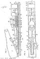
- Fig. 1 is a section along the line I - I in Fig. 2 through the binding in the boarding position and Fig. 2 is a section along the line II - II in Fig. 1.
- Figs. 3 and 4 is a further embodiment reproduced in section along the line III - III in Fig. 4 or in plan view.
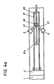
- Fig. 4a shows a slightly modified embodiment compared to Figs. 3 and 4.
- ski-fixed fittings 2, 2 'and 2 are attached to a ski 1, for example by means of screws 3.
- the front fitting 2 has a bend 2a and the middle fitting 2' has a guide 2b.
- the rearmost Fitting 2 has two guide slots 2c, 2d, namely a horizontal 2c and a vertical 2d.
- the fittings 2, 2 ', 2 " is one Sole plate 4 arranged. This is mounted in the bend 2a by means of an extension, which forms a transverse axis 4a, and is guided in the guide 2b by means of a pin 5 with a spherical peripheral surface.
- the sole plate 4 On its two long sides, the sole plate 4 carries four jaws 6, which are designed as two-armed levers and are designed to hold the ski boot 7 from both sides. The jaws 6 are under the influence of springs, not shown, which tend to pivot the jaws into the open position.
- the rear end of the soleplate 4 carries a shoulder 4c, in which a step bracket 8 is mounted on a transverse axis 8a and in which a spring housing 9 with a spring 9a is displaceably guided in the longitudinal direction of the soleplate. Furthermore, an angle lever 10 and a release lever 11 are pivotally mounted in the shoulder 4c, which receives a compression spring 12 in a bore 4d. The bias of this compression spring 12 is adjustable by means of an adjusting screw 13. The other end of the compression spring 12 designed as a helical spring rests against a piston 14 which is guided in the bore 4d. Finally, the shoulder 4c also has a transverse control curve 4e which is approximately triangular in cross section.
- a slide plate 15 is slidably guided in the longitudinal direction of the sole plate, which has approximately wedge-shaped lateral projections 15 a, against which the lower ends of the jaws 6 rest.
- the slide plate 15 has an upwardly projecting shoulder 15b against which the spring 9a accommodated in the spring housing 9 bears.
- the extension 15b extends through a slot in the jacket of the Fe dergeophuses 9.
- the kick bar 8 has elongated holes 8b, in which one end of an articulated bracket 16 is slidably and pivotably arranged, the other end of which is articulated on the shoulder 15b of the slide plate 15. Furthermore, a stop pin 8c is fastened to the stirrup 8 and is intended for bearing against a lug 9b of the spring housing 9. This also has a projection 9c, on which a tension spring 17 is anchored, the other end of which is fastened to the step bracket 8. On its rear side, the spring housing 9 carries a bearing 18 for a roller 19. The end face of one arm of the angle lever 10 is supported on the roller 19 in the driving position of the ski binding. The other arm of the angle lever 10, however, rests on the lateral approaches of the piston 14. The trigger lever 11 has an approach that comes to rest on a side surface of one arm of the angle lever 10 when the trigger lever is depressed and pushes this arm away from the roller 19.
- a follower 20 is supported in the rear end of the sole plate 4. This has an approximately mushroom-shaped shape, with two spherical thickenings being arranged on the stem. One of these thickenings V ER- is, however, performed in the horizontal guide slot 2c the other thickeners located at the end of the handle in the vertical guide slot 2d.
- the head of the follower 20 has a flat end face with which it bears against the piston 14.
- the operation of the ski binding is as follows: when getting in, the ski boot 7 is first lifted from above or by a sliding longitudinal movement with the ebe NEN side surface of his paragraph on the kick bar 8 created. The kick bar 8 is then depressed. In this case, the slide plate 15 is displaced to the right against the force of the spring 9a via the link plate 16 which slides along the upper branch of the control cam 4e with its left end, and the jaws 6 open under the influence of leg springs, not shown in the drawing . Now the ski boot 7 can be inserted between the jaws 6. At the same time, the tension spring 17 is tensioned by the step bracket 8.
- the sole plate 4 is swiveled at a moment in a vertical plane about the transverse axis 4a, the pin 5 moving up or down within the guide 2b. At a moment in a horizontal plane, however, the sole plate 4 is pivoted about the pin 5, the transverse axis 4a sliding to one side in the bend 2a.
- the kick bar 8 is pivoted clockwise about its axis 8a under the influence of a spring designed as a leg spring.
- the g -link bracket 16 slides on the one hand on the right-hand boundary surface of the control cam 4e in FIG. 1 and on the other hand in the elongated holes 8b of the step bracket 8.
- the spring housing 9 is pressed against the action of the tension spring 17 by the stop pin 8c of the step bracket via its nose 9b 8 moved against the ski boot 7 so that the angle lever 10 can return to its normal position.
- the ski binding is therefore ready to start again.
- the release lever 11 is pivoted counterclockwise from the top of the ski pole, where in his approach pushes one arm of the angle lever 10 from the roller 19, which results in the opening of the binding.
- the function of the individual elements of the bond corresponds to that of an involuntary release.
- FIG. 3 and 4 a further embodiment of a ski binding according to the invention is shown.
- the mounting of the sole plate 4 ' which can be pivoted about a transverse axis 4'a and about a vertical axis 4'b, is only indicated.
- a step 8' is articulated. This is articulated via a hinge plate 8'a to a slide plate 15 'which is guided on the top of the sole plate 4' in the longitudinal direction of the ski.
- two jaws 6 are pivotally mounted on axes which lie in a horizontal plane but which form an acute angle with respect to the vertical longitudinal plane of the ski.
- the two jaws 6 are under the influence of springs, not shown, which try to pivot the jaws into the open position.
- the kick bar 8 ' is acted upon by a spring, not shown.
- the rear sides of the two jaws 6 are assigned two wedge-shaped projections 21 on the upper side of the slide plate 15 '. These projections 21 pivot the two jaws 6 against the action of the springs into the clamping position as soon as the slide plate 15 'is pulled towards the end of the ski.
- a piston 22 is rigidly connected to the end of the slide plate 15 'and is guided in a spring housing 23 and acted upon by a compression spring 24.
- Above the spring housing 23 is a heel hold-down device 25, which is connected to the spring housing via a handlebar form a joint parallelogram together with parts 23 and 25.
- the pair of handlebars adjacent to the ski end is extended downward via its hinge axis and articulated by means of elongated holes to a piston 26 which is guided in the spring housing 23 in a freely displaceable manner and is held in its central position by the compression spring 24 and by a further compression spring 27.
- a step spur 28 is articulated on the spring housing 23, which is locked in the entry position of the ski binding with the heel hold-down device 25 by means of a groove and a projection engaging in it.
- the slide plate 15 passes through the spring housing 23 in the form of a piston rod and carries a hook 29 on its end protruding from the spring housing and directed towards the end of the ski, which hook cooperates with an angular locking lever 30 loaded by a spring.
- Behind the lever 30 is a holding device 31 similar to that shown in FIGS. 1 and 2, which cooperates via a follower 20 with a skifedie most fitting 2 "and / on the opposite side of the follower has a plunger 32 which in the Housing of the holding device is guided displaceably and on which one arm of the locking lever 30 rests.
- the ski boot 7 When getting in, the ski boot 7 is guided with the lowered tip along the kick bar 8 'until the heel of the ski boot bears against it. Then the kick bar 8 'is depressed.
- the slide plate 15 'in FIGS. 3 and 4 is shifted to the right via the joint plate 8'a until the slide plate is fastened by means of the hook 29 and the locking lever 30 is held.
- the hinge plate 8'a is then decoupled from the slide plate 15 'by the stop 8'b. In this position, the compression spring 24 is strongly tensioned by the piston 22.
- the locking lever 30 is pivoted clockwise with the aid of a hand lever, not shown, and is thereby lifted out of the hook 29.
- the spring 24 now presses the slide plate 15 'to the left via the piston 22, which results in the jaws 6 opening.
- the piston 26 returns to its central position under the influence of the compression spring 27. This causes the heel hold-down device 25 to be pulled back from the ski boot 7.
- the ski boot 7 can now be lifted unhindered.
- the follower 20 which engages in the ski-fixed fitting 2 ", actuates the holding device 31, which pushes the plunger 32 against the ski tip to such an extent that the hasty lever 30 is lifted out of the hook 29 Jaws 6 and heel hold-down 25 released, as has already been described in detail in the arbitrary release.
- the variant according to FIG. 4a differs from the exemplary embodiment according to FIGS. 3 and 4 in that the kick bar 8 'is not connected to a slide plate via the joint plate 8'a but to a sliding block 36 which is attached to the sole plate 4th 'is slidably guided in the longitudinal direction of the ski.
- On this sliding block 36 are two tie rods 37, the other ends of which are articulated to the jaws 6, and a push rod 38, which is rigidly connected to the piston 22.
- the remaining design of this variant corresponds to that of the exemplary embodiment according to FIGS. 3 and 4.
Landscapes
- Footwear And Its Accessory, Manufacturing Method And Apparatuses (AREA)
- Organic Low-Molecular-Weight Compounds And Preparation Thereof (AREA)
- Materials Applied To Surfaces To Minimize Adherence Of Mist Or Water (AREA)
- Transition And Organic Metals Composition Catalysts For Addition Polymerization (AREA)
Applications Claiming Priority (2)
| Application Number | Priority Date | Filing Date | Title |
|---|---|---|---|
| AT0456982A AT376894B (de) | 1982-12-16 | 1982-12-16 | Ausloeseskibindung |
| AT4569/82 | 1982-12-16 |
Publications (3)
| Publication Number | Publication Date |
|---|---|
| EP0128243A2 true EP0128243A2 (fr) | 1984-12-19 |
| EP0128243A3 EP0128243A3 (en) | 1985-06-19 |
| EP0128243B1 EP0128243B1 (fr) | 1988-07-27 |
Family
ID=3565657
Family Applications (1)
| Application Number | Title | Priority Date | Filing Date |
|---|---|---|---|
| EP83112568A Expired EP0128243B1 (fr) | 1982-12-16 | 1983-12-14 | Fixation de ski à déclenchement |
Country Status (5)
| Country | Link |
|---|---|
| US (1) | US4585250A (fr) |
| EP (1) | EP0128243B1 (fr) |
| JP (1) | JPS59177081A (fr) |
| AT (1) | AT376894B (fr) |
| DE (1) | DE3377466D1 (fr) |
Families Citing this family (5)
| Publication number | Priority date | Publication date | Assignee | Title |
|---|---|---|---|---|
| US5690351A (en) | 1995-07-21 | 1997-11-25 | Karol; Chris | Snowboard binding system |
| DE19653162C1 (de) * | 1996-12-19 | 1998-05-20 | Goodwell Int Ltd | Snowboardbindung |
| US6053524A (en) * | 1997-01-08 | 2000-04-25 | The Burton Corporation | Method and apparatus for indicating when a snowboard binding is locked |
| AT408725B (de) * | 1999-09-21 | 2002-02-25 | Atomic Austria Gmbh | Bindungshaltesystem zur schnellmontage eines vorder- und fersenbackens einer schibindung |
| SI25860A (sl) * | 2019-06-18 | 2020-12-31 | Elan, D.O.O. | Zložljiva smučka |
Family Cites Families (9)
| Publication number | Priority date | Publication date | Assignee | Title |
|---|---|---|---|---|
| FR2190487B1 (fr) * | 1972-07-03 | 1978-03-03 | Salomon Georges P J | |
| DE2401729C2 (de) * | 1973-05-12 | 1982-12-02 | Geze Gmbh, 7250 Leonberg | Sicherheitsskibindung |
| DE2324078B2 (de) * | 1973-05-12 | 1978-09-28 | Vereinigte Baubeschlagfabriken Gretsch & Co Gmbh, 7250 Leonberg | Sicherheitsskibindung |
| GB1512969A (en) * | 1975-11-04 | 1978-06-01 | Ciba Geigy Ag | Photopolymerisable ketones |
| FR2332773A1 (fr) * | 1975-11-26 | 1977-06-24 | Salomon & Fils F | Fixation de securite pour chaussure de ski a rechaussage automatique |
| AT352599B (de) * | 1977-02-23 | 1979-09-25 | Tyrolia Freizeitgeraete | Sicherheitsskibindung |
| FR2385346A1 (fr) * | 1977-03-28 | 1978-10-27 | Beyl Jean Joseph Alfred | Ensemble forme par une chaussure de ski et une fixation specialement concue pour recevoir celle-ci |
| DE2948275A1 (de) * | 1979-11-30 | 1981-06-11 | Geze Gmbh, 7250 Leonberg | Plattensicherheitsskibindung |
| CH645030A5 (fr) * | 1982-01-27 | 1984-09-14 | Haldemann Ag | Fixation de securite d'une chaussure sur un ski et chaussure de ski pour cette fixation. |
-
1982
- 1982-12-16 AT AT0456982A patent/AT376894B/de not_active IP Right Cessation
-
1983
- 1983-12-14 EP EP83112568A patent/EP0128243B1/fr not_active Expired
- 1983-12-14 DE DE8383112568T patent/DE3377466D1/de not_active Expired
- 1983-12-15 US US06/561,714 patent/US4585250A/en not_active Expired - Fee Related
- 1983-12-16 JP JP58236469A patent/JPS59177081A/ja active Pending
Also Published As
| Publication number | Publication date |
|---|---|
| JPS59177081A (ja) | 1984-10-06 |
| DE3377466D1 (en) | 1988-09-01 |
| AT376894B (de) | 1985-01-10 |
| ATA456982A (de) | 1984-06-15 |
| US4585250A (en) | 1986-04-29 |
| EP0128243A3 (en) | 1985-06-19 |
| EP0128243B1 (fr) | 1988-07-27 |
Similar Documents
| Publication | Publication Date | Title |
|---|---|---|
| EP0352662B1 (fr) | Surfaces neiges à fixation pour deux chaussures | |
| DE1428987B2 (de) | Absatzhaltevorrichtung für Skisicherheltsbindungen | |
| DE2953368C2 (fr) | ||
| DE2649826A1 (de) | Sicherheitsbindung zum halten eines schuhs auf einem ski | |
| DE7104814U (de) | Auslösevorrichtung für eine am Ski befestigbare Bremsvorrichtung | |
| DE2332656A1 (de) | Sicherheitsbindung fuer ski | |
| DE69401171T2 (de) | Bindungselement für einen alpinen Ski | |
| DE1578959C3 (de) | Fersenabstützvorrichtung für Sicherheitsskibindungen | |
| DE1478212B2 (de) | Auslösefersenhalter für Skibindungen | |
| EP0128243A2 (fr) | Fixation de ski à déclenchement | |
| EP0118758B1 (fr) | Fixation de ski de sécurité | |
| CH653560A5 (de) | Mit einer skibremse kombinierter fersenhalter. | |
| DE69403402T2 (de) | Skibindungsteil | |
| AT406339B (de) | Snowboardbindung | |
| DE2528578A1 (de) | Sicherheitsbindung fuer skischuhe | |
| DE2907359A1 (de) | Langlauf-sicherheitsskibindung | |
| DE2356908A1 (de) | Sicherheits-skibindung | |
| DE3717788A1 (de) | Sicherheitsskibindung | |
| EP0072903B1 (fr) | Talonnière pour fixation de ski | |
| EP0157091B1 (fr) | Soutien de talon | |
| DE60107995T2 (de) | Vorderbacken einer Skibindung | |
| EP0114662B1 (fr) | Fixation de sécurité pour ski | |
| DE3717101A1 (de) | Sicherheitsskibindung | |
| DE2429610A1 (de) | Sicherheitsskibindung | |
| EP0114664B1 (fr) | Fixation de sécurité pour ski |
Legal Events
| Date | Code | Title | Description |
|---|---|---|---|
| PUAI | Public reference made under article 153(3) epc to a published international application that has entered the european phase |
Free format text: ORIGINAL CODE: 0009012 |
|
| AK | Designated contracting states |
Designated state(s): CH DE FR LI |
|
| 17P | Request for examination filed |
Effective date: 19841201 |
|
| PUAL | Search report despatched |
Free format text: ORIGINAL CODE: 0009013 |
|
| AK | Designated contracting states |
Designated state(s): CH DE FR LI |
|
| 17Q | First examination report despatched |
Effective date: 19860616 |
|
| R17C | First examination report despatched (corrected) |
Effective date: 19870205 |
|
| GRAA | (expected) grant |
Free format text: ORIGINAL CODE: 0009210 |
|
| AK | Designated contracting states |
Kind code of ref document: B1 Designated state(s): CH DE FR LI |
|
| REF | Corresponds to: |
Ref document number: 3377466 Country of ref document: DE Date of ref document: 19880901 |
|
| ET | Fr: translation filed | ||
| PLBE | No opposition filed within time limit |
Free format text: ORIGINAL CODE: 0009261 |
|
| STAA | Information on the status of an ep patent application or granted ep patent |
Free format text: STATUS: NO OPPOSITION FILED WITHIN TIME LIMIT |
|
| 26N | No opposition filed | ||
| PG25 | Lapsed in a contracting state [announced via postgrant information from national office to epo] |
Ref country code: FR Free format text: LAPSE BECAUSE OF NON-PAYMENT OF DUE FEES Effective date: 19890831 |
|
| REG | Reference to a national code |
Ref country code: FR Ref legal event code: ST |
|
| PG25 | Lapsed in a contracting state [announced via postgrant information from national office to epo] |
Ref country code: LI Effective date: 19891231 Ref country code: CH Effective date: 19891231 |
|
| REG | Reference to a national code |
Ref country code: CH Ref legal event code: PL |
|
| PG25 | Lapsed in a contracting state [announced via postgrant information from national office to epo] |
Ref country code: DE Effective date: 19900901 |