EP0128246A1 - Schneidvorrichtung zum Schneiden von Viehfutter oder dergleichem Gewächs, sowie Silagegutschneider oder sonstiges landwirtschaftliches Gerät, ausgeführt mit einer dergleichen Schneidvorrichtung - Google Patents
Schneidvorrichtung zum Schneiden von Viehfutter oder dergleichem Gewächs, sowie Silagegutschneider oder sonstiges landwirtschaftliches Gerät, ausgeführt mit einer dergleichen Schneidvorrichtung Download PDFInfo
- Publication number
- EP0128246A1 EP0128246A1 EP83200867A EP83200867A EP0128246A1 EP 0128246 A1 EP0128246 A1 EP 0128246A1 EP 83200867 A EP83200867 A EP 83200867A EP 83200867 A EP83200867 A EP 83200867A EP 0128246 A1 EP0128246 A1 EP 0128246A1
- Authority
- EP
- European Patent Office
- Prior art keywords
- support member
- cutting device
- knife
- support
- silage cutter
- Prior art date
- Legal status (The legal status is an assumption and is not a legal conclusion. Google has not performed a legal analysis and makes no representation as to the accuracy of the status listed.)
- Withdrawn
Links
Images


Classifications
-
- B—PERFORMING OPERATIONS; TRANSPORTING
- B26—HAND CUTTING TOOLS; CUTTING; SEVERING
- B26D—CUTTING; DETAILS COMMON TO MACHINES FOR PERFORATING, PUNCHING, CUTTING-OUT, STAMPING-OUT OR SEVERING
- B26D7/00—Details of apparatus for cutting, cutting-out, stamping-out, punching, perforating, or severing by means other than cutting
- B26D7/01—Means for holding or positioning work
-
- A—HUMAN NECESSITIES
- A01—AGRICULTURE; FORESTRY; ANIMAL HUSBANDRY; HUNTING; TRAPPING; FISHING
- A01F—PROCESSING OF HARVESTED PRODUCE; HAY OR STRAW PRESSES; DEVICES FOR STORING AGRICULTURAL OR HORTICULTURAL PRODUCE
- A01F25/00—Storing agricultural or horticultural produce; Hanging-up harvested fruit
- A01F25/16—Arrangements in forage silos
- A01F25/20—Unloading arrangements
- A01F25/2027—Unloading arrangements for trench silos
- A01F25/2036—Cutting or handling arrangements for silage blocks
Definitions
- Cutting device for cutting cattle fodder or the like crop, as well as silage cutter, or other agricultural device, carried out with such a cutting device.
- the invention relates to a cutting device for cutting cattle fodder or the like, provided with an upward and downward movable, plate - shaped support member with a support surface which supports at least one plate - shaped knife member designed with teeth, which teeth of the knife member are at least approximately horizontal or can act vertically moving on the crop, as well as on a silage cutter or other agricultural device, carried out with such a cutting device.
- the invention aims to provide a cutting device of the type mentioned in the beginning, in which this disadvantage is overcome in a simple but nevertheless expedient manner.
- the cutting device according to the invention is characterized in that the side of the knife element facing away from the support element encloses an acute angle with the vertical such that the knife element is pressed against the support element by the crop during the downward movement of the support element.
- At least the part of the support element comprising the support surface encloses an acute angle with the vertical.
- the support surface of the support member can be chamfered in the downward direction.
- the support member can be L-shaped or U-shaped with two or three support surfaces, each of which supports a knife member, which knife members together have an L-shaped or U-shaped course, the adjacent ends of the successive knife organs are coupled together by a flexible truncated organ.
- the cutting device is characterized in that the successive straight parts of the support element merge into one another via a curve part, a guide plate for the relevant coupling element in each curve part and the adjoining ends of the straight parts of the support element at the level of the relevant coupling element is arranged.
- a discharge opening is formed in the support member. It is hereby achieved that crop that comes in the corner or the corners of the support member between the knife members and the support member is immediately removed again through the discharge openings formed in the support member.
- the invention further relates to a silage cutter, provided with a frame which can be fastened to a tractor and comprises an upstanding frame part, while a number of parallel carrying tines are fastened to an at least approximately horizontal crossbar.
- This silage cutter is characterized in that it is designed with a cutting device according to the invention.
- the invention relates to an agricultural implement, which is characterized by a cutting device according to the invention.
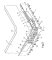
- a perspective view of a silage cutter 1 is shown, which is provided with a cutting device 2 for cutting cattle feed or the like.
- the cutting device 2 is provided with a U-shaped support member 3, which is formed from a sheet metal bent into the desired U-shape.
- the legs of the U-shaped support member 3 enclose an obtuse angle with the web of the support member 3.
- the support member 3 is movable up and down to cut a block of silage from a silage supply, as will be described in more detail below.
- the legs and the web of the support member 3 are each provided with a support surface 4 which, as shown in FIG. 2, supports a plate-shaped knife member 6 with teeth 5.
- the three knife members 6 are adjustable back and forth relative to the support member 3.
- the support member 3 has retaining teeth 7 which protrude downwards relative to the teeth 5 of the knife members 6 and at the same time can act on the crop to be cut with the teeth 5 of the knife members 6. A particularly expedient cutting action of the cutting device 2 is thereby achieved.
- each support surface 4 of the support member 3 is chamfered in the direction of the retaining teeth 7, the angle which the plane of the support surface 4 includes with the plane of the remaining part of the support member 3 is preferably at least 2 ° that the side of the knife elements facing away from the support element 3 encloses an angle of at least 3 ° with the vertical.
- the adjacent ends of the successive knife elements 6 are coupled to one another by a chain 9.
- another flexible coupling element such as a band or the like, can be used.
- a slot 11 is arranged at the level of the chain 9.
- a curved guide plate 12 is attached, which closes the slot 11 for the most part.
- the guide plate 12 carries a bronze guide plate 13 which projects into the slot 11 in question and guides the associated chain 9.
- the chains 9 are therefore somewhat recessed in the slot 11, so that the entrainment of the crop during the reciprocating movement of the knife members 6 is limited to a minimum.
- the bronze guide plate 13 ensures that the heat generated during the movement is rapidly dissipated.
- Each chain consists of a number of links 16, which links 16 are each provided with rounded recesses 17.
- the radius of curvature of these recesses 17 is at least approximately equal to that of the associated one Curve part 10 of the support member 3, so that the links 16 closely connect to the bronze guide plate 13.
- Each chain 9 is further coupled by means of two coupling pieces 18 to the adjacent ends of the associated knife elements 6.
- the dome pieces 18 are attached to the relevant ends of the knife elements 6.
- Each coupling piece 18 has a fork-shaped end 19, the teeth 20 of which run at least approximately horizontally and are connected to the associated end link 16 of the chain 9. Furthermore, the end 19 protrudes into the associated slot 11.
- the silage cutter 1 shown in FIG. 1 and executed with the cutting device 2 is provided with a frame 21 which is designed with attachment points 22 for coupling the silage cutter 1 to the lifting device of a tractor.
- the frame 21 comprises an upright frame part 23 with a horizontal crossbeam 24 at the lower end, to which a number of parallel carrying tines 25 are fastened.
- the U-shaped support member 3 of the cutting device 2 is provided at both ends with supports 26 (see FIGS. 2 and 4), in each of which two wheels 27 are rotatably mounted.
- the support member 3 is guided with the wheels 27 at least approximately in the vertical direction in two C-profiles 28 of the upstanding frame part 23.
- the open sides of the C-profiles 28 are turned away from each other.
- the wheels 27 exert large forces on the C-profiles 28 of the upstanding frame part 23.
- the wheels 27 have a rounded running surface 29, the radius of curvature of the running surface 29 being greater than the radius of curvature of the bent parts 30 of the C-profiles 28.
- each C-profile 28 is carried out at the free ends of the parts 30 with a straight extension 31, which improves the strength of the C-profile 28.
- the upward and downward movement of the U-shaped support member 3 is effected by means of adjustment members carried by the frame 21.
- these adjusting members consist of an upright cylinder-piston unit 32 supported by the frame 21, the piston rod 33 of which carries a disk block 34.
- the support member is upward and adjustable downwards.
- the three knife elements 6, which are coupled to one another by the chains 9, can be adjusted back and forth in the cutting device 2 relative to the support element 3 by means of two cylinder-piston units 37, the piston rods 38 of which at the relevant free ends of those on the legs of the support element 3 located knife organs 6 are attached.
- the cylinder-piston units 37 are supported by the support member 3.
- These cylinder-piston units 37 are double-acting in the exemplary embodiment shown in FIG. 1 and are actuated via a hydraulic changeover valve and check valves in such a way that the piston rods 38 are always adjusted in the opposite direction, as a result of which the knife members 6 receive the desired reciprocating movement.
- the two double-acting cylinder-piston units 37 are also hydraulically coupled to the upright cylinder-piston unit 32, the support member 3 being adjusted step by step, each step coinciding, for example, with a reciprocating movement of the knife members 6.
- Supports 39 for the knife members 6 are arranged on the legs and the web of the U-shaped support member 3, the upper edge of the knife members 6 being adjustable back and forth along the supports. Support the supports 39 downwardly projecting sealing lips 40, as a result of which the knife elements 6 are held in position in cooperation with the connection of the ends of the knife elements to the piston rods 38 of the cylinder-piston units 37 and the coupling pieces 18 guided with their ends 19 in the slots 11.
- the knife members 6 are each only attached at the ends to the support member 3, so that the knife members 6 can be loosened simply by removing the connecting pins 41 which effect the connection to the chains 9 and which are connected by a coupling pin (not shown in the drawing) effected connection with the piston rods 38 is interrupted.
- each connecting pin 41 lies in an at least approximately vertical plane in which the extension of the upper side of the relevant knife element 6 also lies at least approximately.
- the support member 3 is provided at the free ends with supports 42 which protrude downwards relative to the knife members 6 and the retaining teeth 7 of the support member 3 (see FIG. 2).
- the support member 3 is adjustable with the teeth of the knife members 6 beyond the support tines 25 of the frame 21.
- the supports 42 lie on the ground at the end of the cutting cycle, so that the carrying tines 25 are raised somewhat upwards and the cut-out block of silage material is completely released from the silage material supply.
- the U-shaped support member 3 extends obliquely downwards from the upright frame part 23 in the rest position, an angle of approximately 1 ° being included with the horizontal plane. As a result, the support member 3 will be approximately horizontal during operation.
- the invention is not limited to the exemplary embodiment described above, which can be modified in various ways in the context of the invention. For example, it is also possible to equip other agricultural implements for animal feed plants with a cutting device according to the invention.
- the cutting device can also be designed with an L-shaped support member which interacts with two knife members. For certain applications, too a supporting element which has just been executed and which interacts with a knife element is sufficient.
- each support surface of the support member can also cooperate with two knife members, in which case the retaining teeth can be omitted if necessary.
- the knife elements can also be designed to be movable in the vertical direction instead of in the horizontal direction.
- another sliding element can also be used, for example made of plastic.
Landscapes
- Life Sciences & Earth Sciences (AREA)
- Environmental Sciences (AREA)
- Forests & Forestry (AREA)
- Engineering & Computer Science (AREA)
- Mechanical Engineering (AREA)
- Threshing Machine Elements (AREA)
- Harvester Elements (AREA)
- Storage Of Harvested Produce (AREA)
- Nonmetal Cutting Devices (AREA)
- Apparatuses For Bulk Treatment Of Fruits And Vegetables And Apparatuses For Preparing Feeds (AREA)
Priority Applications (8)
| Application Number | Priority Date | Filing Date | Title |
|---|---|---|---|
| EP83200867A EP0128246A1 (de) | 1983-06-13 | 1983-06-13 | Schneidvorrichtung zum Schneiden von Viehfutter oder dergleichem Gewächs, sowie Silagegutschneider oder sonstiges landwirtschaftliches Gerät, ausgeführt mit einer dergleichen Schneidvorrichtung |
| DE19848413777 DE8413777U1 (de) | 1983-06-13 | 1984-05-05 | Schneidvorrichtung zum schneiden von viehfutter od. dgl. gewaechs |
| DE19848428245 DE8428245U1 (de) | 1983-06-13 | 1984-05-05 | Silagegutschneider |
| DE19848428246 DE8428246U1 (de) | 1983-06-13 | 1984-05-05 | Schneidvorrichtung zum schneiden von viehfutter oder dergleichen gewaechs |
| DD26405384A DD225891A5 (de) | 1983-06-13 | 1984-06-12 | Schneidvorrichtung zum schneiden von viehfutter |
| DK287784A DK287784A (da) | 1983-06-13 | 1984-06-12 | Skaereapparat til skaering af kreatur-groentfoder eller tilsvarende plantevaekst, samt en ensilageskaeremekanisme eller andet landbrugsredskab, som er konstrueret med et saadant skaereapparat |
| ES533694A ES533694A0 (es) | 1983-06-13 | 1984-06-13 | Aparato para el corte de piensos y dispositivo para el corte de forraje ensilado que incorpora dicho aparato de corte |
| JP8679384U JPS6019359U (ja) | 1983-06-13 | 1984-06-13 | 飼料等の家畜用植物の切断装置 |
Applications Claiming Priority (1)
| Application Number | Priority Date | Filing Date | Title |
|---|---|---|---|
| EP83200867A EP0128246A1 (de) | 1983-06-13 | 1983-06-13 | Schneidvorrichtung zum Schneiden von Viehfutter oder dergleichem Gewächs, sowie Silagegutschneider oder sonstiges landwirtschaftliches Gerät, ausgeführt mit einer dergleichen Schneidvorrichtung |
Publications (1)
| Publication Number | Publication Date |
|---|---|
| EP0128246A1 true EP0128246A1 (de) | 1984-12-19 |
Family
ID=8190964
Family Applications (1)
| Application Number | Title | Priority Date | Filing Date |
|---|---|---|---|
| EP83200867A Withdrawn EP0128246A1 (de) | 1983-06-13 | 1983-06-13 | Schneidvorrichtung zum Schneiden von Viehfutter oder dergleichem Gewächs, sowie Silagegutschneider oder sonstiges landwirtschaftliches Gerät, ausgeführt mit einer dergleichen Schneidvorrichtung |
Country Status (6)
| Country | Link |
|---|---|
| EP (1) | EP0128246A1 (da) |
| JP (1) | JPS6019359U (da) |
| DD (1) | DD225891A5 (da) |
| DE (3) | DE8413777U1 (da) |
| DK (1) | DK287784A (da) |
| ES (1) | ES533694A0 (da) |
Cited By (3)
| Publication number | Priority date | Publication date | Assignee | Title |
|---|---|---|---|---|
| EP0264157A1 (en) * | 1986-10-16 | 1988-04-20 | C. van der Lely N.V. | An implement for cutting fodder, such as silage |
| CN112868408A (zh) * | 2021-01-15 | 2021-06-01 | 周雨 | 一种畜牧业草料切碎装置 |
| CN113141886A (zh) * | 2021-03-16 | 2021-07-23 | 惠安极地星空科技有限公司 | 一种畜牧用秸秆草料切割装置 |
Families Citing this family (3)
| Publication number | Priority date | Publication date | Assignee | Title |
|---|---|---|---|---|
| DE3520787A1 (de) * | 1985-06-10 | 1986-12-11 | Bernard van Lengerich Maschinenfabrik GmbH & Co, 4448 Emsbüren | Vorrichtung zum schneiden eines blockes aus einem silage-fahrsilo |
| DE3644896C3 (de) * | 1986-01-16 | 1999-06-10 | Lengerich Maschf | Vorrichtung zum Entnehmen von Silagegut |
| DE8625229U1 (de) * | 1986-09-20 | 1987-01-15 | B. Strautmann & Söhne GmbH u. Co, 4518 Bad Laer | Flachsilo-Entnahmegerät |
Citations (2)
| Publication number | Priority date | Publication date | Assignee | Title |
|---|---|---|---|---|
| BE872377Q (fr) * | 1971-07-30 | 1979-03-16 | Bernard Van Lengerich Maschf | Dispositif de decoupage mecanique et de transport de materiau ensile. |
| DE2918650A1 (de) * | 1979-05-09 | 1980-11-20 | Strautmann & Soehne | Geraet zum entnehmen von futterportionen aus silos |
-
1983
- 1983-06-13 EP EP83200867A patent/EP0128246A1/de not_active Withdrawn
-
1984
- 1984-05-05 DE DE19848413777 patent/DE8413777U1/de not_active Expired
- 1984-05-05 DE DE19848428246 patent/DE8428246U1/de not_active Expired
- 1984-05-05 DE DE19848428245 patent/DE8428245U1/de not_active Expired
- 1984-06-12 DK DK287784A patent/DK287784A/da not_active Application Discontinuation
- 1984-06-12 DD DD26405384A patent/DD225891A5/de unknown
- 1984-06-13 JP JP8679384U patent/JPS6019359U/ja active Pending
- 1984-06-13 ES ES533694A patent/ES533694A0/es active Granted
Patent Citations (2)
| Publication number | Priority date | Publication date | Assignee | Title |
|---|---|---|---|---|
| BE872377Q (fr) * | 1971-07-30 | 1979-03-16 | Bernard Van Lengerich Maschf | Dispositif de decoupage mecanique et de transport de materiau ensile. |
| DE2918650A1 (de) * | 1979-05-09 | 1980-11-20 | Strautmann & Soehne | Geraet zum entnehmen von futterportionen aus silos |
Non-Patent Citations (1)
| Title |
|---|
| LANDBOUWMECHANISATIE, Band 34, Nr. 1, Januar 1983, Seiten 51-52, Deventer, NL. * |
Cited By (3)
| Publication number | Priority date | Publication date | Assignee | Title |
|---|---|---|---|---|
| EP0264157A1 (en) * | 1986-10-16 | 1988-04-20 | C. van der Lely N.V. | An implement for cutting fodder, such as silage |
| CN112868408A (zh) * | 2021-01-15 | 2021-06-01 | 周雨 | 一种畜牧业草料切碎装置 |
| CN113141886A (zh) * | 2021-03-16 | 2021-07-23 | 惠安极地星空科技有限公司 | 一种畜牧用秸秆草料切割装置 |
Also Published As
| Publication number | Publication date |
|---|---|
| DE8428245U1 (de) | 1985-04-04 |
| DE8428246U1 (de) | 1985-04-04 |
| ES8504426A1 (es) | 1985-05-01 |
| JPS6019359U (ja) | 1985-02-09 |
| DE8413777U1 (de) | 1985-01-24 |
| DD225891A5 (de) | 1985-08-14 |
| DK287784D0 (da) | 1984-06-12 |
| DK287784A (da) | 1984-12-14 |
| ES533694A0 (es) | 1985-05-01 |
Similar Documents
| Publication | Publication Date | Title |
|---|---|---|
| EP0093318A2 (de) | Entschwartungsmaschine | |
| DE2138186C3 (de) | Gerät zum mechanischen Ausschneiden und zum Transport von Silage | |
| DE2701806C3 (de) | Andrückvorrichtung für Messerklingen einer Mähwerksvorrichtung | |
| DE1507384A1 (de) | Dreschmaschine | |
| EP0102437B2 (de) | Silagegutschneider, sowie landwirtschaftliches Gerät das einen solchen Silagegutschneider aufweist | |
| DE2903271A1 (de) | Schneidemaschine | |
| EP0081742A1 (de) | Über ein Feld vorwärts bewegbares Bodenbearbeitungsgerät | |
| DE8807242U1 (de) | Mähvorrichtung, verstopfungshemmend, dynamisch ausgeglichen | |
| DE2815936A1 (de) | Maehdrescher mit angebautem strohhaecksler | |
| EP0128246A1 (de) | Schneidvorrichtung zum Schneiden von Viehfutter oder dergleichem Gewächs, sowie Silagegutschneider oder sonstiges landwirtschaftliches Gerät, ausgeführt mit einer dergleichen Schneidvorrichtung | |
| DE9101998U1 (de) | Führungsschuh zum Führen des Korns für den Furchenöffner einer Sähmaschine | |
| DE68929086T2 (de) | Mähmaschine | |
| DE2928950C2 (de) | Vorrichtung zum Entnehmen von Gärfutter aus Fahrsilos | |
| EP2139342B1 (de) | Vorrichtung zum aufschneiden eines geschlachteten tieres | |
| EP0140433B1 (de) | Silagegutschneider, sowie landwirtschaftliches Gerät versehen mit einem Aufnahmeorgan, das einen dergleichen Silagegutschneider aufweist | |
| EP0415466B1 (de) | Vorrichtung zum Schneiden von Silagegut aus einem Silagegutvorrat | |
| DE2707030C2 (de) | Schneidwerk für Mähvorrichtungen | |
| DE3751986T2 (de) | Gerät zum Schneiden von Futter, z.B. Silagegut | |
| AT401991B (de) | Schneidvorrichtung für ladewagen | |
| CH660943A5 (de) | Vorrichtung zum ausloesen von knochen. | |
| AT396729B (de) | Waffelblockschneider | |
| DE715927C (de) | Vorrichtung zum maschinellen Aufschneiden flottierender Kettfaeden | |
| DE9116048U1 (de) | Vorrichtung zum gleichmäßigen Ausbreiten von in Haufen ausgebrachtem, langfasrigem Schüttgut | |
| DE102005006257A1 (de) | Ährenheber | |
| DE20103187U1 (de) | Halbierungssäge |
Legal Events
| Date | Code | Title | Description |
|---|---|---|---|
| PUAI | Public reference made under article 153(3) epc to a published international application that has entered the european phase |
Free format text: ORIGINAL CODE: 0009012 |
|
| 17P | Request for examination filed |
Effective date: 19840514 |
|
| AK | Designated contracting states |
Designated state(s): AT BE CH DE FR GB IT LI LU NL SE |
|
| RAP1 | Party data changed (applicant data changed or rights of an application transferred) |
Owner name: TRIOLIET MULLOS B.V. |
|
| STAA | Information on the status of an ep patent application or granted ep patent |
Free format text: STATUS: THE APPLICATION HAS BEEN WITHDRAWN |
|
| 18W | Application withdrawn |
Withdrawal date: 19851024 |
|
| RIN1 | Information on inventor provided before grant (corrected) |
Inventor name: LIET, CORNELIS HENDRICUS Inventor name: LIET, FREDERICUS |