EP0128281A2 - Chariot sur rails avec dispositif de freinage - Google Patents
Chariot sur rails avec dispositif de freinage Download PDFInfo
- Publication number
- EP0128281A2 EP0128281A2 EP84103506A EP84103506A EP0128281A2 EP 0128281 A2 EP0128281 A2 EP 0128281A2 EP 84103506 A EP84103506 A EP 84103506A EP 84103506 A EP84103506 A EP 84103506A EP 0128281 A2 EP0128281 A2 EP 0128281A2
- Authority
- EP
- European Patent Office
- Prior art keywords
- bolt
- support arm
- brake
- brakable
- running rail
- Prior art date
- Legal status (The legal status is an assumption and is not a legal conclusion. Google has not performed a legal analysis and makes no representation as to the accuracy of the status listed.)
- Granted
Links
- 230000000694 effects Effects 0.000 description 5
- 238000005096 rolling process Methods 0.000 description 4
- 230000036316 preload Effects 0.000 description 2
- 230000006835 compression Effects 0.000 description 1
- 238000007906 compression Methods 0.000 description 1
- 238000005065 mining Methods 0.000 description 1
- 238000000926 separation method Methods 0.000 description 1
Images


Classifications
-
- B—PERFORMING OPERATIONS; TRANSPORTING
- B65—CONVEYING; PACKING; STORING; HANDLING THIN OR FILAMENTARY MATERIAL
- B65G—TRANSPORT OR STORAGE DEVICES, e.g. CONVEYORS FOR LOADING OR TIPPING, SHOP CONVEYOR SYSTEMS OR PNEUMATIC TUBE CONVEYORS
- B65G9/00—Apparatus for assisting manual handling having suspended load-carriers movable by hand or gravity
- B65G9/002—Load-carriers, rollers therefor
-
- A—HUMAN NECESSITIES
- A61—MEDICAL OR VETERINARY SCIENCE; HYGIENE
- A61H—PHYSICAL THERAPY APPARATUS, e.g. DEVICES FOR LOCATING OR STIMULATING REFLEX POINTS IN THE BODY; ARTIFICIAL RESPIRATION; MASSAGE; BATHING DEVICES FOR SPECIAL THERAPEUTIC OR HYGIENIC PURPOSES OR SPECIFIC PARTS OF THE BODY
- A61H3/00—Appliances for aiding patients or disabled persons to walk about
- A61H3/008—Appliances for aiding patients or disabled persons to walk about using suspension devices for supporting the body in an upright walking or standing position, e.g. harnesses
-
- B—PERFORMING OPERATIONS; TRANSPORTING
- B65—CONVEYING; PACKING; STORING; HANDLING THIN OR FILAMENTARY MATERIAL
- B65G—TRANSPORT OR STORAGE DEVICES, e.g. CONVEYORS FOR LOADING OR TIPPING, SHOP CONVEYOR SYSTEMS OR PNEUMATIC TUBE CONVEYORS
- B65G9/00—Apparatus for assisting manual handling having suspended load-carriers movable by hand or gravity
- B65G9/006—Arresting, braking or escapement means
Definitions
- the invention relates to a brakeable carriage for running rails, in particular for running rail systems for disabled persons, with a supporting arm, at the lower end of which an object to be carried can be hung and at the upper end of which rollers are arranged such that they are on the lower flanks of the running rail can roll in the longitudinal direction of the rail, and a braking element which can be brought into engagement with the running rail.
- Trolleys for running tracks are not only needed on hanging roller shutters or on monorails in mining, but also in the clinic, rehabilitation and living area for the disabled - primarily as a walking aid.
- a brakable trolley for box-shaped runners in which a a lower longitudinal slot of the rail engaging wedge clamps in this longitudinal slot when a train is exerted in the direction of loading. This prevents undesired rolling of the car while changing trains.
- this known car has the disadvantage that it is not in the unloaded state is braked so that an accidental bumping of the car in the direction of travel leads to rolling and a disabled person can no longer reach the car or the rope ladder attached to it.
- the object of the invention is to design a brakable carriage for running rails of the type mentioned at the outset such that it is braked in the unloaded state and the brake is released in the loaded state. Furthermore, it is desirable that the carriage under a particularly high load, such as e.g. if a disabled person holding onto the car falls or when he moves from one seat or couch to another, the brakes are also applied automatically; in the case of such a separate “movement” and “camber brake”, in particular a pressure point should be provided after the movement brake has been released and before the camber brake is gripped.
- At least one spring-loaded bolt is guided transversely to the direction of movement of the rollers on the support arm, a hook or eye for hanging a load is arranged at the lower end of the bolt, and a braking element is arranged at the upper end of the bolt and the spring in the unloaded state of the support arm holds the braking element in a vertical extreme position, in particular in the highest position, for braking engagement with a surface of the running rail.
- the advantage of the invention is that the braking element locks the carriage in the running rail as long as the spring force pushing it up is not exceeded by a weight hanging on the bolt. It is therefore possible to adjust the spring force by adjusting the preload of the spring or by selecting a special spring in such a way that the brake is only released from a predetermined minimum load.
- the minimum force releasing the brake can be specified according to the intended use.
- running tracks for such purposes i.a. those with a double-T-shaped cross-section, but especially those with a box-shaped cross-section, are suitable for ceiling mounting, in which two opposing lower flanks leave a longitudinal slot between their longitudinal edges for guiding a support arm, the rollers preferably being arranged in pairs inside the box-shaped profile and can roll on the inner surface of the flanks in the longitudinal direction of the rail.
- brakable carriages are preferred which, according to a further development of the invention, also have an "overload and / or camber brake” in addition to the "motion brake” described above.
- a further braking element is arranged at the upper end of one of the bolts, which in the fully loaded state of the support arm rests frictionally against a surface of the running rail, that is to say can be brought into braking engagement with the running rail.
- the braking element of the motion brake is a brake wedge which, in its highest position, is in braking engagement with the edges of the lower longitudinal slot of a box-shaped running rail.
- a cone-shaped brake wedge in which the cone axis coincides with the pin axis, has the advantage that it remains effective in any position relative to the pin. Knurling the outer surface of the brake cone or an otherwise roughened outer surface increases the braking effect.
- An overload and / or camber brake of the car according to the invention results according to a further development of the invention for this first embodiment by a brake disc attached to the bolt above the brake wedge and extending transversely to the bolt for frictional engagement on the lower flanks within the running rail in the fully loaded state Condition of the support arm.
- This brake disc is rigid or connected to the bolt by a joint, so that the full braking surface of the brake disc can also be effective in the event of an overload acting obliquely on the bolt.
- This braking surface is also preferably roughened in order to increase the braking force.
- This second embodiment has the advantage that a pressure point is provided after releasing the motion brake and before gripping the overload and / or camber brake, so that after the motion brake is released, only a very small, in particular predeterminable, force is required , there is a predefinable load range within which triggering of the overload and / or camber brake is definitely excluded.
- This separation of functions between the two types of brakes means that each of the two brakes can be optimally designed for its special task using simple means.
- a particularly simple and effective version of this second embodiment provides, however, that at least the camber and / or overload brake acts upwards against the running rail, so that the carriage between the braking element of the overload and / or camber brake on the one hand and the running surfaces for the rollers on the other hand is spread.
- the springs act in opposite directions on the associated bolts such that the pivot point of the lever after the first brake element has been released from the corresponding surface of the running rail from the lower pivot point of the first bolt to the lower pivot point of the second bolt.
- a precisely defined pressure point is created in that the movement path of the first pin is limited by a stop.
- a particular advantage of this second embodiment of the invention consists in the fine adjustability and adjustability of the triggering forces for both brakes.
- the two springs not only have different spring constants, but their support points on the carriage and / or the bolts are height-adjustable.
- the lever arm length can be adjusted in a simple manner toward the point of application of the load, so that there is a considerable expansion of the adjustment range for both brakes.
- Such a brakable car can therefore, for example, by simply adjusting the braking release forces of very light people, such as children, as well as of overweight people People are used.
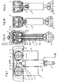
- a first braked carriage 1 for a box-shaped running rail 2 with a lower longitudinal slot 3 consists of two support plates 4, 5, at the lower ends of which an object to be carried, not shown in the drawing, can be suspended in a rotatable or pivotable eyelet 6.
- rollers 7 and 8 are arranged at the upper ends such that they can roll on the lower, opposite flanks 9, 10 within the box-shaped running rail 2 in the longitudinal direction of the rail.
- the rollers 7 and 8 are preferably rotatably mounted in pairs on a common axis inserted through the support plate 4 and 5, respectively.
- a sleeve 11 aligned at right angles to the running rail 2 is welded to the support plates 4, 5 on opposite sides in a central plane and forms the support arm together with these; it receives a bolt 12 axially displaceable.
- This bolt 12 carries at its lower end the eyelet 6 and at its upper end a conical brake wedge 13 as well as a brake disc 15 which is arranged at a distance above it and can be pivoted about a joint 14 and which on its underside - as well as the outer surface of the brake wedge 13 - for the purpose of improving it Braking effect is corrugated or roughened.
- a special brake lining can also be provided.
- a helical spring 16 surrounds the bolt 12 within the sleeve 11 and is supported on the one hand on a collar 17 of the sleeve 11 and on the other hand on the lower end face of the brake wedge 13. It therefore acts on the brake wedge 13 as a compression spring, so that in the unloaded state the brake wedge 13 is pushed so far up that it is wedged so tightly with the edges 18, 19 of the flanks 9, 10 of the running rail 2 that the carriage 1 cannot continue to roll. Then the brake disc 15 is arranged unloaded on all sides within the running rail 2 and the brake wedge in its highest position.
- the brake wedge 13 lifts off from the edges 18, 19 of the longitudinal slot 3 of the running rail 2 and releases the carriage 1 for rolling in the running rail 2, because then the brake disc 15 is still freely located on all sides within the running rail (Fig. 2b). Only in the event of a jerky or otherwise further tensile load on the eyelet 6 is the spring 16 compressed to such an extent that the underside of the brake disc 15 comes to rest with the flanks 9, 10 of the running rail 2 and prevents the carriage 1 from further rolling.
- both the triggering force for the brake wedge 13 and the maximum force for the brake disk 15 to take effect can be adjusted by appropriate choice of the spring or an adjustment of the spring preload.
- a triggering force for the brake wedge 13 of approximately 50 N and a maximum force for the effectiveness of the brake disc 15 of 70 N make sense.
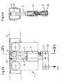
- a second brakable carriage 1 ' consists of a support arm 4, 5, 11', within the sleeve 11 'of which the bolts 20 and 21 are guided transversely to the direction of movement of the rollers 7, 8.
- the bolt 20 is held in the unloaded state P o of the load application point 29 in an uppermost position, in which a braking element 23 is in braking engagement with the surface 25 of the running rail 2.
- the further pin 21 also guided in the sleeve 11 'is acted upon in the opposite sense by a spring 24 which keeps the associated brake element 22 of this pin 21 away from the surface 25 of the running rail 2.
- the bolts 20 and 21 pivotally engage at articulation points 30 and 31 of a lever 26 at a distance a in the longitudinal direction A of the lever 26.
- the spring constant of the spring 16 ' is considerably smaller than that of the spring 24, so that the pivot point of the lever 26 lies in the articulation point 31 of the bolt 21 at a relatively low triggering force P 1 (FIG. 3b).
- P 1 triggering force
- the stop 32 of the bolt 20 takes effect, the pivot point of the lever 26 shifts from the articulation point 31 to the articulation point 30, so that the lever 26 is now a two-armed lever, at its load application point 29 at a distance b from the articulation point 30 one between P 1 and P 2 attacks lying load.
- This load is transmitted with the lever length a via the pivot point 31 to the bolt 21.
- the braking element 22 of the bolt 21 comes into braking engagement with the surface 25 of the running rail 2 (FIG. 3 c).
Landscapes
- Engineering & Computer Science (AREA)
- Mechanical Engineering (AREA)
- Health & Medical Sciences (AREA)
- Epidemiology (AREA)
- Pain & Pain Management (AREA)
- Physical Education & Sports Medicine (AREA)
- Rehabilitation Therapy (AREA)
- Life Sciences & Earth Sciences (AREA)
- Animal Behavior & Ethology (AREA)
- General Health & Medical Sciences (AREA)
- Public Health (AREA)
- Veterinary Medicine (AREA)
- Braking Arrangements (AREA)
- Chain Conveyers (AREA)
- Carriers, Traveling Bodies, And Overhead Traveling Cranes (AREA)
Priority Applications (1)
| Application Number | Priority Date | Filing Date | Title |
|---|---|---|---|
| AT84103506T ATE36238T1 (de) | 1983-06-04 | 1984-03-30 | Bremsbarer wagen fuer laufschienen. |
Applications Claiming Priority (2)
| Application Number | Priority Date | Filing Date | Title |
|---|---|---|---|
| DE3320281A DE3320281C1 (de) | 1983-06-04 | 1983-06-04 | Bremsbarer Wagen fuer Laufschienen |
| DE3320281 | 1983-06-04 |
Publications (3)
| Publication Number | Publication Date |
|---|---|
| EP0128281A2 true EP0128281A2 (fr) | 1984-12-19 |
| EP0128281A3 EP0128281A3 (en) | 1985-11-27 |
| EP0128281B1 EP0128281B1 (fr) | 1988-08-10 |
Family
ID=6200690
Family Applications (1)
| Application Number | Title | Priority Date | Filing Date |
|---|---|---|---|
| EP84103506A Expired EP0128281B1 (fr) | 1983-06-04 | 1984-03-30 | Chariot sur rails avec dispositif de freinage |
Country Status (3)
| Country | Link |
|---|---|
| EP (1) | EP0128281B1 (fr) |
| AT (1) | ATE36238T1 (fr) |
| DE (2) | DE3320281C1 (fr) |
Cited By (9)
| Publication number | Priority date | Publication date | Assignee | Title |
|---|---|---|---|---|
| EP0223930A3 (en) * | 1985-11-19 | 1988-01-13 | Hespe & Woelm Gmbh & Co. Kg | Transporting apparatus for persons |
| FR2707924A1 (fr) * | 1993-07-21 | 1995-01-27 | Conception Manutention Commerc | Chariot de manutention d'une charge équipé de moyens de liaison temporaire avec un autre chariot. |
| ES2068123A2 (es) * | 1993-03-12 | 1995-04-01 | Autet Enrique Mas | Conjunto de gancho deslizador y rieles. |
| EP0997130A3 (fr) * | 1998-10-27 | 2000-11-15 | Gilbert John Flynn | Aide au mouvement |
| US20110028871A1 (en) * | 2008-04-07 | 2011-02-03 | Honda Motor Co., Ltd. | Curved guide mechanism and walking assist device |
| EP2609967A3 (fr) * | 2011-12-28 | 2015-03-18 | Transol Corporation | Chariot d'ancrage et système anti-chute et son procédé de mise en 'uvre |
| DE102011007135B4 (de) * | 2010-04-21 | 2015-08-20 | Honda Motor Co., Ltd. | Herstellungsverfahren für bogenförmige Schiene |
| US20180169448A1 (en) * | 2009-07-10 | 2018-06-21 | Transol Corporation | Anchor trolley and fall arrest system and method implementing the same |
| CN114570035A (zh) * | 2022-03-02 | 2022-06-03 | 北京科技大学 | 一种具有记忆性且可行驶多种轨迹的无碳小车 |
Families Citing this family (1)
| Publication number | Priority date | Publication date | Assignee | Title |
|---|---|---|---|---|
| DE3911777A1 (de) * | 1989-04-11 | 1990-10-18 | Hessabi Iradj | Vorrichtung zum heben und senken von lasten |
Family Cites Families (4)
| Publication number | Priority date | Publication date | Assignee | Title |
|---|---|---|---|---|
| US2834435A (en) * | 1954-08-17 | 1958-05-13 | Alfred G Vanderbeck | Crane anchoring device |
| US3861318A (en) * | 1973-10-05 | 1975-01-21 | Michael J Massa | Safety ski harness cable system |
| FR2373997A1 (fr) * | 1976-12-15 | 1978-07-13 | Marteil Theodule | Appareil de marche |
| FR2523856A1 (fr) * | 1982-03-26 | 1983-09-30 | Forjot Roland | Appareil pour apprendre la pratique du ski |
-
1983
- 1983-06-04 DE DE3320281A patent/DE3320281C1/de not_active Expired
-
1984
- 1984-03-30 AT AT84103506T patent/ATE36238T1/de not_active IP Right Cessation
- 1984-03-30 EP EP84103506A patent/EP0128281B1/fr not_active Expired
- 1984-03-30 DE DE8484103506T patent/DE3473224D1/de not_active Expired
Cited By (12)
| Publication number | Priority date | Publication date | Assignee | Title |
|---|---|---|---|---|
| EP0223930A3 (en) * | 1985-11-19 | 1988-01-13 | Hespe & Woelm Gmbh & Co. Kg | Transporting apparatus for persons |
| ES2068123A2 (es) * | 1993-03-12 | 1995-04-01 | Autet Enrique Mas | Conjunto de gancho deslizador y rieles. |
| FR2707924A1 (fr) * | 1993-07-21 | 1995-01-27 | Conception Manutention Commerc | Chariot de manutention d'une charge équipé de moyens de liaison temporaire avec un autre chariot. |
| EP0997130A3 (fr) * | 1998-10-27 | 2000-11-15 | Gilbert John Flynn | Aide au mouvement |
| US6389618B1 (en) | 1998-10-27 | 2002-05-21 | Gilbert John Flynn | Movement aid |
| US20110028871A1 (en) * | 2008-04-07 | 2011-02-03 | Honda Motor Co., Ltd. | Curved guide mechanism and walking assist device |
| US20180169448A1 (en) * | 2009-07-10 | 2018-06-21 | Transol Corporation | Anchor trolley and fall arrest system and method implementing the same |
| US10617897B2 (en) * | 2009-07-10 | 2020-04-14 | Transol Coporation | Anchor trolley and fall arrest system and method implementing the same |
| DE102011007135B4 (de) * | 2010-04-21 | 2015-08-20 | Honda Motor Co., Ltd. | Herstellungsverfahren für bogenförmige Schiene |
| EP2609967A3 (fr) * | 2011-12-28 | 2015-03-18 | Transol Corporation | Chariot d'ancrage et système anti-chute et son procédé de mise en 'uvre |
| CN114570035A (zh) * | 2022-03-02 | 2022-06-03 | 北京科技大学 | 一种具有记忆性且可行驶多种轨迹的无碳小车 |
| CN114570035B (zh) * | 2022-03-02 | 2022-11-15 | 北京科技大学 | 一种具有记忆性且可行驶多种轨迹的无碳小车 |
Also Published As
| Publication number | Publication date |
|---|---|
| ATE36238T1 (de) | 1988-08-15 |
| DE3320281C1 (de) | 1985-01-31 |
| EP0128281A3 (en) | 1985-11-27 |
| EP0128281B1 (fr) | 1988-08-10 |
| DE3473224D1 (en) | 1988-09-15 |
Similar Documents
| Publication | Publication Date | Title |
|---|---|---|
| DE69306727T2 (de) | Sicherheitsabseilvorrichtung | |
| EP1294631B1 (fr) | Dispositif de freinage pour un ascenseur | |
| DE2626425C2 (de) | Sicherheitsvorrichtung an einer Leiter mit einem Laufwagen | |
| WO2013045358A1 (fr) | Système de freinage à actionnement électromécanique | |
| EP0128281A2 (fr) | Chariot sur rails avec dispositif de freinage | |
| DE1034927B (de) | Reibungsstossdaempfer | |
| EP1400476A1 (fr) | Parachute pour ascenseurs | |
| DE69604968T2 (de) | Wagenblockierkeil | |
| DE2730959B2 (de) | Zuspannvorrichtung für Reibungsbremsen, insbesondere von Schienenfahrzeugen | |
| DE3521198C2 (de) | Notbremsvorrichtung für ein schienengebundenes Fahrzeug | |
| WO1985002169A1 (fr) | Dispositif parachute notamment pour cabines d'ascenseur | |
| DE925071C (de) | Keilfangvorrichtung an Personen- und Lastenaufzuegen | |
| EP0017762B1 (fr) | Dispositif de support pour un frein à tambour | |
| DE2604157A1 (de) | Bremsfangvorrichtung | |
| DE8418128U1 (de) | Gleisbremselement | |
| DE8316388U1 (de) | Bremsbarer wagen fuer laufschienen | |
| EP0243758B1 (fr) | Attelage automatique pour véhicules ferroviaires | |
| DE1406188C3 (de) | Bremsfangvorrichtung fur Aufzuge | |
| DE392415C (de) | Schienenbremse | |
| DE1232183C2 (de) | Bremsvorrichtung fuer Laufwerke von Haengebahnen | |
| DE193967C (fr) | ||
| DE568136C (de) | Fangvorrichtung fuer seillos gewordene Foerderwagen | |
| EP1159987A2 (fr) | Frein de câble | |
| CH568870A5 (en) | Brake system for ski lifts and cableways - has wedge shaped needle bearing mounted emergency brake | |
| DE1406199C (de) | Fangvorrichtung |
Legal Events
| Date | Code | Title | Description |
|---|---|---|---|
| PUAI | Public reference made under article 153(3) epc to a published international application that has entered the european phase |
Free format text: ORIGINAL CODE: 0009012 |
|
| AK | Designated contracting states |
Designated state(s): AT BE CH DE FR GB IT LI NL SE |
|
| PUAL | Search report despatched |
Free format text: ORIGINAL CODE: 0009013 |
|
| AK | Designated contracting states |
Designated state(s): AT BE CH DE FR GB IT LI NL SE |
|
| 17P | Request for examination filed |
Effective date: 19851221 |
|
| 17Q | First examination report despatched |
Effective date: 19870515 |
|
| GRAA | (expected) grant |
Free format text: ORIGINAL CODE: 0009210 |
|
| AK | Designated contracting states |
Kind code of ref document: B1 Designated state(s): AT BE CH DE FR GB IT LI NL SE |
|
| REF | Corresponds to: |
Ref document number: 36238 Country of ref document: AT Date of ref document: 19880815 Kind code of ref document: T |
|
| GBT | Gb: translation of ep patent filed (gb section 77(6)(a)/1977) | ||
| REF | Corresponds to: |
Ref document number: 3473224 Country of ref document: DE Date of ref document: 19880915 |
|
| ITF | It: translation for a ep patent filed | ||
| ET | Fr: translation filed | ||
| PLBE | No opposition filed within time limit |
Free format text: ORIGINAL CODE: 0009261 |
|
| STAA | Information on the status of an ep patent application or granted ep patent |
Free format text: STATUS: NO OPPOSITION FILED WITHIN TIME LIMIT |
|
| 26N | No opposition filed | ||
| ITTA | It: last paid annual fee | ||
| EAL | Se: european patent in force in sweden |
Ref document number: 84103506.6 |
|
| PGFP | Annual fee paid to national office [announced via postgrant information from national office to epo] |
Ref country code: FR Payment date: 19980119 Year of fee payment: 15 |
|
| PGFP | Annual fee paid to national office [announced via postgrant information from national office to epo] |
Ref country code: GB Payment date: 19980126 Year of fee payment: 15 |
|
| PGFP | Annual fee paid to national office [announced via postgrant information from national office to epo] |
Ref country code: SE Payment date: 19980320 Year of fee payment: 15 Ref country code: AT Payment date: 19980320 Year of fee payment: 15 |
|
| PGFP | Annual fee paid to national office [announced via postgrant information from national office to epo] |
Ref country code: BE Payment date: 19980323 Year of fee payment: 15 |
|
| PGFP | Annual fee paid to national office [announced via postgrant information from national office to epo] |
Ref country code: CH Payment date: 19980325 Year of fee payment: 15 |
|
| PGFP | Annual fee paid to national office [announced via postgrant information from national office to epo] |
Ref country code: NL Payment date: 19980330 Year of fee payment: 15 |
|
| PGFP | Annual fee paid to national office [announced via postgrant information from national office to epo] |
Ref country code: DE Payment date: 19980519 Year of fee payment: 15 |
|
| PG25 | Lapsed in a contracting state [announced via postgrant information from national office to epo] |
Ref country code: GB Free format text: LAPSE BECAUSE OF NON-PAYMENT OF DUE FEES Effective date: 19990330 Ref country code: AT Free format text: LAPSE BECAUSE OF NON-PAYMENT OF DUE FEES Effective date: 19990330 |
|
| PG25 | Lapsed in a contracting state [announced via postgrant information from national office to epo] |
Ref country code: SE Free format text: LAPSE BECAUSE OF NON-PAYMENT OF DUE FEES Effective date: 19990331 Ref country code: LI Free format text: LAPSE BECAUSE OF NON-PAYMENT OF DUE FEES Effective date: 19990331 Ref country code: CH Free format text: LAPSE BECAUSE OF NON-PAYMENT OF DUE FEES Effective date: 19990331 Ref country code: BE Free format text: LAPSE BECAUSE OF NON-PAYMENT OF DUE FEES Effective date: 19990331 |
|
| BERE | Be: lapsed |
Owner name: HESPE & WOELM G.M.B.H. & CO. K.G. Effective date: 19990331 |
|
| PG25 | Lapsed in a contracting state [announced via postgrant information from national office to epo] |
Ref country code: NL Free format text: LAPSE BECAUSE OF NON-PAYMENT OF DUE FEES Effective date: 19991001 |
|
| EUG | Se: european patent has lapsed |
Ref document number: 84103506.6 |
|
| REG | Reference to a national code |
Ref country code: CH Ref legal event code: PL |
|
| GBPC | Gb: european patent ceased through non-payment of renewal fee |
Effective date: 19990330 |
|
| PG25 | Lapsed in a contracting state [announced via postgrant information from national office to epo] |
Ref country code: FR Free format text: LAPSE BECAUSE OF NON-PAYMENT OF DUE FEES Effective date: 19991130 |
|
| NLV4 | Nl: lapsed or anulled due to non-payment of the annual fee |
Effective date: 19991001 |
|
| EUG | Se: european patent has lapsed |
Ref document number: 84103506.6 |
|
| REG | Reference to a national code |
Ref country code: FR Ref legal event code: ST |
|
| PG25 | Lapsed in a contracting state [announced via postgrant information from national office to epo] |
Ref country code: DE Free format text: LAPSE BECAUSE OF NON-PAYMENT OF DUE FEES Effective date: 20000101 |