EP0128327A2 - Procédé et dispositif de commande de l'alimentation en carburant d'un moteur à combustion - Google Patents
Procédé et dispositif de commande de l'alimentation en carburant d'un moteur à combustion Download PDFInfo
- Publication number
- EP0128327A2 EP0128327A2 EP84104962A EP84104962A EP0128327A2 EP 0128327 A2 EP0128327 A2 EP 0128327A2 EP 84104962 A EP84104962 A EP 84104962A EP 84104962 A EP84104962 A EP 84104962A EP 0128327 A2 EP0128327 A2 EP 0128327A2
- Authority
- EP
- European Patent Office
- Prior art keywords
- idle
- combustion engine
- internal combustion
- switching
- accelerator pedal
- Prior art date
- Legal status (The legal status is an assumption and is not a legal conclusion. Google has not performed a legal analysis and makes no representation as to the accuracy of the status listed.)
- Ceased
Links
Images


Classifications
-
- F—MECHANICAL ENGINEERING; LIGHTING; HEATING; WEAPONS; BLASTING
- F02—COMBUSTION ENGINES; HOT-GAS OR COMBUSTION-PRODUCT ENGINE PLANTS
- F02D—CONTROLLING COMBUSTION ENGINES
- F02D41/00—Electrical control of supply of combustible mixture or its constituents
- F02D41/02—Circuit arrangements for generating control signals
- F02D41/04—Introducing corrections for particular operating conditions
- F02D41/08—Introducing corrections for particular operating conditions for idling
-
- F—MECHANICAL ENGINEERING; LIGHTING; HEATING; WEAPONS; BLASTING
- F02—COMBUSTION ENGINES; HOT-GAS OR COMBUSTION-PRODUCT ENGINE PLANTS
- F02D—CONTROLLING COMBUSTION ENGINES
- F02D41/00—Electrical control of supply of combustible mixture or its constituents
- F02D41/02—Circuit arrangements for generating control signals
- F02D41/04—Introducing corrections for particular operating conditions
- F02D41/12—Introducing corrections for particular operating conditions for deceleration
- F02D41/123—Introducing corrections for particular operating conditions for deceleration the fuel injection being cut-off
- F02D41/126—Introducing corrections for particular operating conditions for deceleration the fuel injection being cut-off transitional corrections at the end of the cut-off period
Definitions
- the invention is based on a method for controlling the fuel supply to an internal combustion engine with an idle shut-off device in the range of the push operation according to the preamble of the main claim.
- a method for controlling the fuel supply to an internal combustion engine with an idle shut-off device in the range of the push operation according to the preamble of the main claim is known from DE-OS (R 4356 of the applicant).
- DE-OS R 4356 of the applicant.
- Such a method enables a motor vehicle equipped with an internal combustion engine to be braked in push operation.
- a jerk occurs because of the sudden restart of the fuel supply and thereby the comfort and to a certain extent the safety while driving is impaired.
- the above-mentioned method with the associated device avoids torque jumps by interrupting the fuel supply at the beginning and reinserting it the fuel supply at the end of pushing operation is not sudden, but soft.
- the fuel supply is either reduced or increased again according to a defined function.
- the relatively high level of driving comfort achieved is, however, paid for
- the method according to the invention with the characterizing features of the main claim has the advantage that a sufficiently pleasant driving behavior is achieved with a relatively low switching effort and the resulting small construction volume and cost ratio.
- the method according to the invention is also applicable to carburetor engines - and can be used there particularly advantageously.
- Another advantage is the introduction of the lower speed threshold, which enables a smooth termination of the push operation and a smooth and smooth transition to idle.
- Driving comfort is further increased by introducing a blocking period; when changing gear, the idle fuel quantity continues to be supplied to the internal combustion engine during this blocking time.
- the device comprises a number of building blocks known in principle, which are operatively connected to one another in a meaningful and advantageous manner.
- the logical combination of the components as well as further details and advantageous refinements can be found in the description in conjunction with the drawing and the claims.
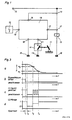
- Figure 1 shows the device according to the invention in a block diagram
- Figure 2 shows a circuit diagram with the individual modules
- Figure 3 shows a functional diagram.
- an accelerator pedal 11, an ignition device 12 and an idle shutoff valve 13 are shown as known elements of a motor vehicle.
- An accelerator pedal switch 14 is mechanically connected to the accelerator pedal 11.
- the winding of the idle shut-off valve 13 is usually between a terminal 15 and a ground connection 16.
- the supply line from the terminal 15 to the idle shut-off valve 13 is interrupted in accordance with the invention, in its place is the port 15 and another port 17 of a fuel cut-off device 18.
- the port 17 represents the output of the fuel cut-off device 18.
- An input 19 of the fuel cut-off device 18 is connected to an ignition device 12, a second input 21 of the fuel cut-off device 18 is located at one end of the accelerator pedal switch 14.
- the other end of the accelerator pedal switch 14 is connected to ground 16.
- FIG. 2 shows the individual building blocks and components of the overrun cutoff device 18. Only functionally essential elements are specified. Between the input 19 and the ground connection 16 there is an input voltage divider with a series circuit comprising a diode 22 and a resistor 23 and a parallel circuit comprising a resistor 24 and a capacitor 25. The base of a pre-stage transistor 26 is connected to the connection point of the voltage divider. The ignition device 12 is used as a speed sensor.
- a first threshold value stage 27 is provided for a lower speed threshold n 1 , which essentially comprises the series connection of a voltage comparator 28 and two inverters 29 and 31.
- the non-inverting input of the voltage comparator 28 is connected to a fixed voltage divider with the resistors 32 and 33 on a supply line 34 with a screened voltage and via a series connection of a resistor 35 and a diode 36 at the output of the second inverter 31.
- the inverting input of the voltage comparator 28 is connected to the collector of the pre-stage transistor 26, which in turn is connected to the supply line 34 via a load resistor 37 and to ground 16 via a capacitor 38.
- the voltage comparator 28 is provided with a load resistor 39 and a block capacitor 41.
- a second threshold value stage 42 is provided, which, connected in series, comprises a voltage comparator 43 and two inverters 44 and 45.
- the voltage comparator 43 has a load resistor 46 and a blocking capacitor 47.
- the non-inverting input of the S pan Vietnameseparators 43 is again connected to the tap of a fixed voltage divider with the resistors 48 and 49 and via a series circuit of a resistor 51 and a diode 52 to the output of second inverter 45 connected.
- the screened voltage is the line 34 from the. Terminal 15 is supplied via a filter resistor 53 in connection with a filter capacitor 54 and a Zener diode 55.
- connection 21 of the accelerator pedal switch 14 is connected to the input of a pre-switching stage 56.
- the connecting line is led to the base of a switching pre-stage transistor 59 via resistors 57 and 58.
- resistors 57 and 58 Between the connection point of the two resistors 57 and 58 and the ground connection 16 there is a zener diode 61, between the input of the switching preamplifier and the emitter of the transistor 59 there is a resistor 62.
- the emitter of the transistor 59 is connected directly to the connection 15.
- the collector of transistor 59 of switching pre-stage 56 is connected to the input of a switching output stage 63.
- the switching output stage 63 comprises an output stage transistor 64 and a base series resistor 65, which is located at the input of the switching output stage 63.
- the emitter of the output stage transistor 64 is connected to the ground terminal 16, a switching relay 66 is inserted as a load resistor between the collector of the transistor 64 and the terminal 15.
- the winding of the switching relay 66 is bridged in the usual way with a freewheeling diode 67.
- the relay 66 of the switching output stage 63 is operatively connected to a switch 68, the connections of which are on the one hand to the terminal 15 and on the other hand via a diode 69 to the ground connection 16 and to the connection 17 of the overrun cutoff device 18.
- the diode 69 serves as a freewheeling diode for the idle shutoff valve 13.
- a monostable multivibrator 71 is provided, which comprises a negating AND circuit 72 and an inverter 73.
- the input of the inverter 73 is connected to ground 16 via a resistor 74 and to the output of the AND circuit 72 via a capacitor 75.
- the output of inverter 73 is connected directly to an input of AND circuit 72.
- the other input of the AND circuit 73 and thus the input of the monostable multivibrator 71 is connected to the output of a negating AND circuit 76 via a switching point D which will be required later.
- a second negating AND circuit 77 is also provided.
- An input of the AND circuit 76 is connected to an input of the AND circuit 77 and also to the connection point of the two resistors 57 and 58 of the switching pre-stage 56. This connecting line is also led to the input of an astable multivibrator 78 and a negating AND circuit 79.
- the other input of the AND circuit 79 is connected to the output of the monostable multivibrator 71; the output of the AND circuit 79 is connected via a diode 71 at the switching point C and thus at the input of the switching output stage 63.
- the other input of the AND circuit 76 is at the output of the first threshold value stage 27 and at the same time at an input of a negating AND circuit 82.
- the other input of the AND circuit 77 is at a switching point G mentioned again later and at the output of the second threshold stage 42.
- the output of the AND circuit 77 is at a switching point F and at the input of a further negating AND circuit 83.
- the other input the further AND circuit 83 is connected to the output of the AND circuit 82; the output of the further AND circuit 83 is at the input an inverter 84. From the output of the inverter 84, a line leads via a diode 85 to the switching point C and thus to the input of the switching output stage 63.
- the switching point C is also connected via a diode 86 to a switching point A, which in turn is connected to the connecting line between the inverter 29 and the inverter 31 of the first threshold stage 27 is connected.
- the astable multivibrator 78 comprises two inverting AND circuits 87 and 88.
- the AND circuit 88 is connected as an inverter, its input is connected to the output of the AND circuit 87 and to one end of a resistor 89. From the other end of the resistor 89, a capacitor 91 leads to the output of the inverter 88 and a resistor 92 leads to the other input of the UNn circuit 87.
- the output of the AND circuit and thus the output of the astable multivibrator 78 is at the other input of the AND circuit 82.
- Figure 3 is a functional diagram.
- Figure 3a shows, depending on the time t, the speed curve n for a transition to the push mode. The speed decreases from a value above the speed n 2 .
- the position of the throttle valve is outlined in FIG. 3b. First the throttle valve is open. If gas is removed, the throttle valve is closed at time t 1 and remains closed.
- Figure 3c shows the position of the idle valve. The idle valve is initially open, it remains open beyond time t 1 . After the expiry of a blocking period that extends from time t1 to time t2 extends, the throttle valve is closed at time t 2 .
- the idle valve is opened and closed intermittently. If the speed n falls below the lower threshold value n 1 at time t 4 , the idle valve is opened completely again and remains open.
- the idle fuel quantity is shown in FIG. It is fully supplied up to time t 2 , completely switched off from time t 2 to time t 3 , partly supplied from time t 3 to time t 4 and made fully available again from time t 4 .
- Three speed states of the internal combustion engine are evaluated by the two threshold switches 27 and 42. Depending on the instantaneous speed of the internal combustion engine, on the position of the accelerator pedal 11 and on whether a shift is taking place, there are five cases.
- the measuring point M represents the enable input for the astable multivibrator 78.
- n 1 When the internal combustion engine is idling with the motor vehicle stationary, the speed n is below the lower speed threshold n 1 .
- a first time constant ⁇ 1 becomes effective from the resistor 37 and the capacitor 38 and a second time constant ⁇ 2 from the resistor 39 and the capacitor 41;
- a time constant ⁇ 3 comes from the resistor 46 and the capacitor 47 under the conditions is the switching point A in Figure 2 at H potential.
- the transistor 64 of the switching output stage 63 is thus turned on, the relay 66 is excited, the switching contact 88 is closed and that
- Idle shutoff valve 13 energized.
- the supply of the idle fuel quantity is not disrupted.
- the accelerator pedal switch 14 controlled by the accelerator pedal 11 is open and has no influence.
- the transistor 59 of the pre-switching stage 56 is turned on via the accelerator pedal switch 14.
- the switching point C goes to H potential via the collector transistor 59.
- the transistor 64 of the switching output stage 63 also becomes conductive, the relay 66 picks up and the idle shut-off valve 13 is kept in the current-carrying state via the switch 68.
- the monostable multivibrator 71 is provided.
- the monostable multivibrator 71 can emit a pulse of approximately half a second in duration, during which time switching point C is kept at H potential.
- the transistor 64 of the switching stage 63 and thus also the idle shut-off valve 13 is kept live.
- the monostable multivibrator 71 then emits the pulse when an edge H - L arises at the switching point D. This is the case under the condition described.
- the switching point M has an H potential when the accelerator pedal switch 14 is open. As already mentioned above, the switching point M serves as a release for the astable multivibrator 78 and also as a release for the AND circuit 79.
- the switching point A is at L potential.
- the transistor 59 of the switching pre-stage 56 is blocked.
- the monostable multivibrator 71 outputs its pulse mentioned. If the accelerator pedal switch 14 is still open afterwards, a new switching condition is added: the switching point E has H potential, the switching point G has L potential and leads the switching point F to H potential. But now the AND circuit 83 is controlled conductive.
- the switching pulses of the astable multivibrator 38 are switched through to the switching point C, the transistor 64 of the switching stage 63 is switched on and off intermittently.
- a ratio of 1: 1 is provided as the duty cycle.
- the idle shut-off valve 13 is also switched on and off intermittently by the transistor 64 via the relay 66 switches. As soon as the speed n drops below the speed threshold n 1 during pushing operation, the switching point E receives an L potential from the first speed threshold 27 and thus influences the AND circuit 82 so that the switching point C remains at H potential. The intermittent signal is thus converted into a continuous switch-on signal.
- the astable multivibrator 78 can no longer be effective after the pulse emitted by the monostable multivibrator 71 has expired, since the switching point G is at H potential and the switching point F is at L- Potential lies.
- the idle shut-off valve 13 is de-energized. If the speed n of the internal combustion engine then drops below the upper threshold value n 2 , the astable multivibrator 78 is released again. The idle shut-off valve 13 is again switched on and off intermittently. If the speed n drops further, namely below the lower threshold value n 1 , the idle shut-off valve 13 remains switched on continuously.
Landscapes
- Engineering & Computer Science (AREA)
- Chemical & Material Sciences (AREA)
- Combustion & Propulsion (AREA)
- Mechanical Engineering (AREA)
- General Engineering & Computer Science (AREA)
- Electrical Control Of Air Or Fuel Supplied To Internal-Combustion Engine (AREA)
- Control Of The Air-Fuel Ratio Of Carburetors (AREA)
Applications Claiming Priority (2)
| Application Number | Priority Date | Filing Date | Title |
|---|---|---|---|
| DE19833320359 DE3320359A1 (de) | 1983-06-06 | 1983-06-06 | Verfahren zum steuern der kraftstoffzufuhr zu einer brennkraftmaschine |
| DE3320359 | 1983-06-06 |
Publications (2)
| Publication Number | Publication Date |
|---|---|
| EP0128327A2 true EP0128327A2 (fr) | 1984-12-19 |
| EP0128327A3 EP0128327A3 (fr) | 1985-07-03 |
Family
ID=6200743
Family Applications (1)
| Application Number | Title | Priority Date | Filing Date |
|---|---|---|---|
| EP84104962A Ceased EP0128327A3 (fr) | 1983-06-06 | 1984-05-03 | Procédé et dispositif de commande de l'alimentation en carburant d'un moteur à combustion |
Country Status (3)
| Country | Link |
|---|---|
| EP (1) | EP0128327A3 (fr) |
| JP (1) | JPS603466A (fr) |
| DE (1) | DE3320359A1 (fr) |
Families Citing this family (5)
| Publication number | Priority date | Publication date | Assignee | Title |
|---|---|---|---|---|
| AUPS270602A0 (en) * | 2002-05-31 | 2002-06-20 | Baron, Peter | Drink flavouring straw |
| DE102005002275B4 (de) * | 2005-01-18 | 2015-02-05 | Andreas Stihl Ag & Co. Kg | Verfahren zum Betrieb eines Einzylinder-Zweitaktmotors |
| DE102005002273B4 (de) * | 2005-01-18 | 2017-08-10 | Andreas Stihl Ag & Co. Kg | Verfahren zum Betrieb eines Einzylinder-Zweitaktmotors |
| AR060029A1 (es) | 2006-03-02 | 2008-05-21 | Unistraw Patent Holdings Ltd | Pajilla para beber adaptada para acondicionar progresivamente un ingrediente activo y metodo de fabricar dicha pajilla |
| DE102023114937A1 (de) | 2023-06-07 | 2024-12-12 | Dr. Ing. H.C. F. Porsche Aktiengesellschaft | Verfahren und System zur Steuerung einer Kraftstoffzufuhr einer Brennkraftmaschine |
Family Cites Families (6)
| Publication number | Priority date | Publication date | Assignee | Title |
|---|---|---|---|---|
| IT1023750B (it) * | 1974-09-19 | 1978-05-30 | Chicocini R | Dispositivo di controllo della erogazione di propellente liquido o gassoso per motori a combustione interna in specie destinati alla autotrazione |
| DE2516347A1 (de) * | 1975-04-15 | 1976-10-28 | Bosch Gmbh Robert | Elektrische steuereinrichtung mit schutz gegen masse-kurzschluss |
| DE2801790A1 (de) * | 1978-01-17 | 1979-07-19 | Bosch Gmbh Robert | Verfahren und einrichtung zur steuerung der kraftstoffzufuhr zu einer brennkraftmaschine |
| JPS5650232A (en) * | 1979-09-28 | 1981-05-07 | Nissan Motor Co Ltd | Controlling device for fuel |
| JPS5654933A (en) * | 1979-10-12 | 1981-05-15 | Nissan Motor Co Ltd | Fuel cut device |
| JPS56107927A (en) * | 1980-01-31 | 1981-08-27 | Nissan Motor Co Ltd | Fuel feeder |
-
1983
- 1983-06-06 DE DE19833320359 patent/DE3320359A1/de not_active Ceased
-
1984
- 1984-05-03 EP EP84104962A patent/EP0128327A3/fr not_active Ceased
- 1984-05-23 JP JP10277984A patent/JPS603466A/ja active Pending
Also Published As
| Publication number | Publication date |
|---|---|
| EP0128327A3 (fr) | 1985-07-03 |
| JPS603466A (ja) | 1985-01-09 |
| DE3320359A1 (de) | 1984-12-06 |
Similar Documents
| Publication | Publication Date | Title |
|---|---|---|
| DE2801790C2 (fr) | ||
| DE2844290C2 (de) | Schaltungsanordnung zum Steuern der Kraftstoffeinspritzung einer Kraftstoffeinspritzanlage für eine Brennkraftmaschine | |
| DE2162072A1 (de) | Elektronische Steuervorrichtung für eine automatische Kraftübertragungsanlage | |
| DE1626427B1 (de) | Vorrichtung zur Veränderung der Drehzahl beim Schalten eines selbsttätig schaltenden Kraftfahrzeuggetriebes | |
| DE2163979B2 (de) | Kraftstoffeinspritzsystem für den Motor eines ein automatisches Getriebe enthaltenden Fahrzeugs | |
| DE2416838A1 (de) | Automatisches elektronisches fernsteuersystem, insbesondere zur steuerung hydrodynamischer getriebe in kraftfahrzeugen | |
| EP0130341B1 (fr) | Procédé et dispositif de commande d'un moteur à combustion interne en décélération | |
| DE2700548A1 (de) | Sicherheitsschaltung fuer elektronische getriebesteuerungen | |
| DE3026423A1 (de) | Geschwindigkeitsbegrenzungsvorrichtung fuer kraftfahrzeuge | |
| DE2926106C2 (de) | Verfahren und Anordnung zum Betrieb einer Fahrzeug-Brennkraftmaschine | |
| DE1906941A1 (de) | Elektronische Anordnung zur Steuerung einer elektromagnetischen Kupplung | |
| DE2517697A1 (de) | Verfahren und vorrichtung zur drehzahlbegrenzung bei brennkraftmaschinen | |
| DE2419987C2 (de) | Regelanordnung für einen batteriegespeisten fremderregten Gleichstrom-Antriebsmotor eines Straßenfahrzeuges | |
| DE3146934C2 (de) | Anordnung zum Steuern einer elektromagnetischen Kupplung für ein Kraftfahrzeug | |
| EP0128327A2 (fr) | Procédé et dispositif de commande de l'alimentation en carburant d'un moteur à combustion | |
| DE3334723A1 (de) | Einrichtung zur steuerung eines motors und/oder einer automatisierten kupplung von kraftfahrzeugen | |
| DE3241024C2 (fr) | ||
| DE2246935A1 (de) | Bremslichtsystem | |
| EP0140152A2 (fr) | Dispositif de commande d'un moteur à combustion interne en décélération | |
| DE2853995C2 (de) | Antriebsaggregat mit einem Handschaltgetriebe, einer Brennkraftmaschine und Mitteln zur Verringerung der Geräuschemission | |
| DE3435338A1 (de) | Fahrzeugwechselgetriebe | |
| DE2842390A1 (de) | Elektronische schaltvorrichtung fuer die betaetigung eines overdrives | |
| EP0033939A2 (fr) | Dispositif de régulation d'alimentation en carburant par la buse de ralenti d'un moteur à combustion interne | |
| EP1297987A1 (fr) | Commande de moteur pour un véhicule à boíte de vitesses manuelle | |
| DE1981032U (de) | Einrichtung zum abstellen der kraftstoffzufuhr bei otto-motoren im schiebebetrieb. |
Legal Events
| Date | Code | Title | Description |
|---|---|---|---|
| PUAI | Public reference made under article 153(3) epc to a published international application that has entered the european phase |
Free format text: ORIGINAL CODE: 0009012 |
|
| 17P | Request for examination filed |
Effective date: 19840503 |
|
| AK | Designated contracting states |
Designated state(s): DE FR GB IT |
|
| PUAL | Search report despatched |
Free format text: ORIGINAL CODE: 0009013 |
|
| AK | Designated contracting states |
Designated state(s): DE FR GB IT |
|
| STAA | Information on the status of an ep patent application or granted ep patent |
Free format text: STATUS: EXAMINATION IS IN PROGRESS |
|
| 17Q | First examination report despatched |
Effective date: 19861003 |
|
| 18R | Application refused |
Effective date: 19870621 |
|
| RIN1 | Information on inventor provided before grant (corrected) |
Inventor name: SCHEMITZEK, ERICH |