EP0128485A2 - Echappement dans un plancher pour des installations de ventilation et de conditionement d'air - Google Patents
Echappement dans un plancher pour des installations de ventilation et de conditionement d'air Download PDFInfo
- Publication number
- EP0128485A2 EP0128485A2 EP84106284A EP84106284A EP0128485A2 EP 0128485 A2 EP0128485 A2 EP 0128485A2 EP 84106284 A EP84106284 A EP 84106284A EP 84106284 A EP84106284 A EP 84106284A EP 0128485 A2 EP0128485 A2 EP 0128485A2
- Authority
- EP
- European Patent Office
- Prior art keywords
- floor outlet
- floor
- grate
- air
- outlet according
- Prior art date
- Legal status (The legal status is an assumption and is not a legal conclusion. Google has not performed a legal analysis and makes no representation as to the accuracy of the status listed.)
- Granted
Links
Images
Classifications
-
- G—PHYSICS
- G05—CONTROLLING; REGULATING
- G05D—SYSTEMS FOR CONTROLLING OR REGULATING NON-ELECTRIC VARIABLES
- G05D23/00—Control of temperature
- G05D23/19—Control of temperature characterised by the use of electric means
- G05D23/20—Control of temperature characterised by the use of electric means with sensing elements having variation of electric or magnetic properties with change of temperature
-
- F—MECHANICAL ENGINEERING; LIGHTING; HEATING; WEAPONS; BLASTING
- F24—HEATING; RANGES; VENTILATING
- F24F—AIR-CONDITIONING; AIR-HUMIDIFICATION; VENTILATION; USE OF AIR CURRENTS FOR SCREENING
- F24F11/00—Control or safety arrangements
- F24F11/70—Control systems characterised by their outputs; Constructional details thereof
- F24F11/72—Control systems characterised by their outputs; Constructional details thereof for controlling the supply of treated air, e.g. its pressure
- F24F11/74—Control systems characterised by their outputs; Constructional details thereof for controlling the supply of treated air, e.g. its pressure for controlling air flow rate or air velocity
- F24F11/76—Control systems characterised by their outputs; Constructional details thereof for controlling the supply of treated air, e.g. its pressure for controlling air flow rate or air velocity by means responsive to temperature, e.g. bimetal springs
-
- F—MECHANICAL ENGINEERING; LIGHTING; HEATING; WEAPONS; BLASTING
- F24—HEATING; RANGES; VENTILATING
- F24F—AIR-CONDITIONING; AIR-HUMIDIFICATION; VENTILATION; USE OF AIR CURRENTS FOR SCREENING
- F24F13/00—Details common to, or for air-conditioning, air-humidification, ventilation or use of air currents for screening
- F24F13/02—Ducting arrangements
- F24F13/06—Outlets for directing or distributing air into rooms or spaces, e.g. ceiling air diffuser
Definitions
- the invention relates to a floor outlet for ventilation and air conditioning systems with a grate over an opening in the floor.
- Rooms that are connected to a ventilation or air conditioning system are usually ventilated via so-called ceiling openings. These have the advantage that the rooms in question can be ventilated without draft and that the air which is supplied, if appropriate tempered, mixes with the room air without further ado and without drafts. In some cases, however, it is not possible to arrange ceiling outlets. Then it is necessary to provide floor outlets. The usually cold air then enters the room immediately. This results in undesirable drafts and within wide limits also temperature differences e.g. between floor area and ceiling area.
- the object of the invention is to provide a floor outlet with which draft-free ventilation of rooms with the same temperature distribution in the room is possible.
- the grate consists of ring elements arranged concentrically to one another and in that a guide body for generating a vortex with a vertebra axis oriented essentially perpendicular to the grate plane is arranged under the grate.
- the guide body can in particular be a disk with guide vanes extending radially therefrom, which are twisted against the plane of the disk.
- Such a guide body is easy to manufacture and is nevertheless effective.
- the ring elements of the grate can be connected to one another via radial ribs, which can have approximately the same angle of attack as the guide vanes of the guide body, so that they do not disturb the vortex generated in the area of the guide body.
- An air chamber can be located below the guide body be arranged with inlet connection. This air chamber serves to calm the air entering the air chamber, which air then emerges from the floor outlet essentially without interference and only with the vortex generated by the guide body.
- the air chamber can expediently have an annular cross section and a central dome, the inlet port opening radially into the air chamber.
- the air flow entering the air chamber is deflected accordingly and calmed in the ring chamber surrounding the dome.
- the floor outlet is easily accessible and can be easily installed if the grate and the guide body are arranged in a recess in a ring insert which is supported on the dome of the air chamber.
- the ring insert and the air chamber can each have ring flanges which cover or underside a base plate, the ring insert and the air chamber being able to be braced against one another with a screw arranged in the region of the dome. This allows the floor outlet to be securely clamped in the opening of a floor slab. Nevertheless, the grate and guide body remain accessible because they can be lifted out of the ring insert. This has other advantages as described below.
- Ventilation and air conditioning systems usually include temperature control with room thermostats.
- the room thermostats are usually placed on a wall of the room. They deliver an elek trical signal that is fed to a central controller that regulates the temperature and / or volume of the supplied air.
- a central controller that regulates the temperature and / or volume of the supplied air.
- floor inlets are also provided through which the used room air is extracted. These floor inlets are connected to a piping system installed under the floor, which is connected to a vacuum source that sucks the used room air out, discharges it outside or supplies it to the ventilation and air conditioning system.
- Such a system can be used advantageously according to the invention if a duct opens close to the grate and is connected to the vacuum source for extracting the room air and if a temperature sensor is arranged in the duct.
- This temperature sensor is part of a thermostat in the usual way and is connected via this to the controller of the ventilation or air conditioning system.
- the channel can advantageously have a constriction between its mouth and the temperature sensor. Otherwise, the channel can be arranged in a jacket of the ring insert.
- an actual value transmitter and a comparator connected to the actual value transmitter and to the temperature sensor for emitting a control signal in the floor outlet, so that at least the actual one after lifting the grate and possibly the guide body Value encoder, e.g. a potentiometer can be accessible.
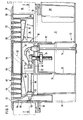
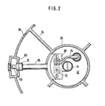
- the floor outlet shown has an upper ring insert 10 and a lower air chamber 12.
- the floor outlet is arranged in a circular floor opening.
- the ring insert 10 is inserted into the ground from above and the air chamber 12 from below.
- the two parts are connected to each other by an axially arranged screw 14 so that they clamp the edge of a base plate 16 between them.
- the air chamber 12 is bowl-shaped. It has an annular flange 18 and a central dome 20 with a flat upper side 22, under which there is a socket for a nut 24 into which the screw 14 is screwed.
- the dome 20 forms a shoulder 26 approximately halfway up, so that the support of the ring insert 10 is improved. This will be explained in detail later.
- An inlet port 20 radially, which can be connected to a ventilation or air conditioning system, not shown.
- a vertical recess 30 is provided in the wall of the air chamber 12 diametrically opposite the inlet connection 28, the purpose of which will also be explained later.
- the air conditioned in the ventilation or air conditioning system enters through the inlet connection 28 into an annular chamber 31 which surrounds the dome 20 and which is open at the top.
- the air chamber accordingly serves to deflect the incoming horizontal air jet vertically upwards and to distribute it over an annular cross section.
- the ring insert 10 has a central collar which is formed in one piece with radial webs 34 and a cylindrical jacket 36 which is coaxial with the collar 32.
- the upper edge of the jacket 36 merges into an annular flange 38.
- the ring flange 38 extends over the edge of a bottom opening, so that the associated bottom plate is clamped between the ring flange 38 of the ring insert 10 and the ring flange 18 of the air chamber 12.
- the central collar carries a mounting plate 40 which extends across the interior of the collar 32.
- the screw 14 is passed through an opening in the mounting plate 40.
- a guide body 42 is supported on the upper edge of the collar 32.
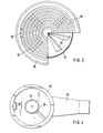
- This guide body consists of a disk 44, from which a plurality of guide vanes 46 extend in the radial direction.
- FIGS. 1 and 3 A comparison of FIGS. 1 and 3 reveals that the planes of the guide vanes 46 are inclined to the vertical.
- the guide body 42 has been produced from a sheet metal disk which has been provided with radial incisions. The guide vanes 46 between the cuts were then twisted.
- a recess 47 for receiving the guide body 42 is provided on each radial web 34.
- the ring insert 10 forms a recess defined by its jacket 36, in which a circular grate 48 is arranged directly above the guide body 42.
- the grate consists of several concentrically arranged ring elements 50, the thickness of which decreases vertically downwards.
- the ring elements 50 are connected to one another via four ribs 52 arranged at the same angle, which start from the innermost ring element and extend beyond the outermost ring element and are supported on the inside of the jacket 36.
- Each rib 52 has the same depth as the ring elements 50. However, the ribs 52 are inclined, as is shown in FIG. 1 with dashed lines. The angle of incidence of the ribs 52 is approximately 40 ° to the vertical.
- the circular region which is defined by the innermost ring element 50, is covered by a continuous plate 54, which has two circular and concentric recesses 56 on its upper side.
- the dimensions of the recesses 56 correspond to the dimensions of the spaces between the ring elements 50.
- a similar ring-shaped recess 58 is located on the ring flange 58 of the ring insert 10, so that the impression is created that ring-shaped openings extend over the entire surface of the floor outlet.
- a vertical channel 60 is arranged.
- This channel 60 has an opening 62 which is arranged in the region of the recess 58 of the ring flange 20.
- Most of the channel 60 has a rectangular cross section, the dimension of which is the same as the dimension of the mouth 62 in the circumferential direction, but the radial dimension of which is considerably larger.
- the radial dimension of the channel 60 in the illustrated embodiment is greater in the radial direction by a factor of 1.75 than at the mouth 62.
- the channel 60 extends in the vertical direction approximately to the lower edge of the collar 32 and within the recess 30 on the Air chamber 12.
- a constriction 64 is located between the mouth 62 and the region of essentially the same cross-section, the smallest radial dimension of which, in the embodiment shown, is approximately half the size of the corresponding radial dimension at the mouth 62.
- a temperature sensor 63 is arranged on an arm 66 in the area of the constant cross sections within the channel 60, which extends in the radial direction up to a bracket 68 which is arranged on the top of the mounting plate 40.
- a conical sealing ring 70 on the outer end of the arm 66 seals an associated opening for the arm in the air chamber 12.
- the temperature sensor can be a thermocouple, a thermostat or a semiconductor element. Regardless of its structure, the temperature sensor 63 delivers an electrical signal, which is indicated on the console 68 ordered circuit is compared with the signal of a set potentiometer 72. The comparison signal is passed on to a remote controller via lines 74.
- the air entering the air chamber 12 through the inlet connector 28 is deflected upward in an annular air flow.
- the air chamber 12 defines an annular chamber 31, which is designed from a fluidic point of view.
- the dome has the shoulder 26 so that the lower edge of the collar 32 of the ring insert 10 does not form a protruding edge.
- the annular chamber 31 serves to calm the horizontally entering Air jet, which is deflected upwards with low losses and especially with low noise.
- the upward-directed annular air flow then strikes the guide vanes 46 of the guide body 42.
- the guide vanes 46 generate a vortex, the vortex axis of which is directed essentially perpendicular to the plane of the floor.
- the annular air jet set in rotation in the region of the guide body 42 then passes through the annular channels between the ring elements 50, which do not provide any significant resistance to the rotary movement.
- the ribs 52 could form a resistance to the rotational movement of the air jet, but, as described above, they have approximately the same angle of attack as the guide vanes 46 of the guide body 42 and therefore do not oppose the rotational movement. Accordingly, the vortex generated in the area of the guide body 42 also continues outside the floor outlet in the room.
- the air emerging from the floor outlet mixes quickly with the ambient air, it quickly loses its speed, so that a rapid temperature compensation is guaranteed.
- the vacuum system is designed to generate a differential pressure of no more than 10 Pascals between the room and the piping system located under the floor under the floor.
- this low Differential pressure is sufficient to draw a substantial part of the room air through the mouth 62 into the channel 60 and thus via the temperature sensor 63. It was not to be expected that this would be possible even with such low differential pressures, particularly in the immediate vicinity of the air vortex emerging upwards.
- the signal emitted by the temperature sensor 63 can then be used to regulate the volume of the air to be supplied to the room in question. In practice it is sufficient if one floor outlet of several connected to the same volume flow controllers is equipped with a temperature sensor 63, while the other floor outlets are only controlled as well.
- the ability to carry out precise temperature measurements of the indoor air in the floor makes temperature control much easier and easier. Separate room thermostats and assigned lines to the central controller are unnecessary.
- the electrical connection of the temperature sensor 63 in the floor outlet to the associated volume controller can be very simple and in particular can be laid along the supply line for the air.
- the guide body 42 can also be designed differently. It can have wings or baffle plates which are arranged either in the ring insert 10 or within the air chamber 12.
- the air chamber should, however, be designed as a calming and stabilizing chamber in such a way that it supplies the vortex generating device with an upward, calming air jet with a low noise level.
- the manufacture of the guide body 42 from a sheet metal plate has the advantage of great simplicity. Nevertheless, other constructions are also possible, for example made of plastic injection molding.
- the construction of the guide body 42 on the other hand, can take place solely with a view to producing a vortex according to optimal aerodynamic considerations.
- a temperature sensor can be omitted.
- a temperature sensor may or may not be provided.
- the essential components of the floor outlet should be made of metal. Versions made of plastic can also be used for other applications.
- blind rings can also be inserted into the annular recesses between the ring elements 50 in order to connect the floor outlet to other flow conditions, e.g. at lower flow velocities.
Landscapes
- Engineering & Computer Science (AREA)
- Physics & Mathematics (AREA)
- Chemical & Material Sciences (AREA)
- Combustion & Propulsion (AREA)
- Mechanical Engineering (AREA)
- General Engineering & Computer Science (AREA)
- Fluid Mechanics (AREA)
- General Physics & Mathematics (AREA)
- Automation & Control Theory (AREA)
- Duct Arrangements (AREA)
- Air-Flow Control Members (AREA)
- Ventilation (AREA)
Priority Applications (1)
| Application Number | Priority Date | Filing Date | Title |
|---|---|---|---|
| AT84106284T ATE38553T1 (de) | 1983-06-08 | 1984-06-01 | Fussbodenauslass fuer lueftungs- und klimaanlagen. |
Applications Claiming Priority (2)
| Application Number | Priority Date | Filing Date | Title |
|---|---|---|---|
| GB8315688 | 1983-06-08 | ||
| GB838315688A GB8315688D0 (en) | 1983-06-08 | 1983-06-08 | Air conditioner outlet |
Publications (3)
| Publication Number | Publication Date |
|---|---|
| EP0128485A2 true EP0128485A2 (fr) | 1984-12-19 |
| EP0128485A3 EP0128485A3 (en) | 1986-06-18 |
| EP0128485B1 EP0128485B1 (fr) | 1988-11-09 |
Family
ID=10543959
Family Applications (1)
| Application Number | Title | Priority Date | Filing Date |
|---|---|---|---|
| EP84106284A Expired EP0128485B1 (fr) | 1983-06-08 | 1984-06-01 | Echappement dans un plancher pour des installations de ventilation et de conditionement d'air |
Country Status (6)
| Country | Link |
|---|---|
| US (1) | US4549474A (fr) |
| EP (1) | EP0128485B1 (fr) |
| AT (1) | ATE38553T1 (fr) |
| DE (1) | DE3475099D1 (fr) |
| GB (1) | GB8315688D0 (fr) |
| ZA (1) | ZA844322B (fr) |
Cited By (1)
| Publication number | Priority date | Publication date | Assignee | Title |
|---|---|---|---|---|
| DE8802921U1 (de) * | 1988-03-04 | 1988-05-05 | Mero-Werke Dr.-Ing. Max Mengeringhausen GmbH & Co, 8700 Würzburg | Luftdüsenplatte als Einbauteil für Doppelbodenplatten |
Families Citing this family (9)
| Publication number | Priority date | Publication date | Assignee | Title |
|---|---|---|---|---|
| US5938525A (en) | 1997-07-23 | 1999-08-17 | Tompkins Industries, Inc | Air diffuser, and mold and method for its production |
| US6083100A (en) * | 1999-02-08 | 2000-07-04 | Gebruder Trox Gmbh | Underfloor air diffuser assembly |
| US6361432B1 (en) | 1999-08-17 | 2002-03-26 | Tomkins Industries, Inc. | Air diffuser with air flow regulator |
| US7641125B2 (en) * | 2005-04-29 | 2010-01-05 | E.H. Price Ltd. | Variable air volume ceiling diffuser |
| US20070092374A1 (en) * | 2005-10-12 | 2007-04-26 | Zamalis Michael H | Air Diffuser |
| US9028309B2 (en) * | 2007-05-30 | 2015-05-12 | Price Companies, Inc. | Diffuser mounting flange |
| US20110132022A1 (en) * | 2009-12-03 | 2011-06-09 | Kun-Yu Liang | Air flow regulator for air conditioner |
| CN102313346B (zh) * | 2010-06-29 | 2015-04-08 | 珠海格力电器股份有限公司 | 一种空调室内机 |
| US20190368770A1 (en) * | 2018-05-29 | 2019-12-05 | John P. Hanus | Under Cabinet Ventilation System |
Family Cites Families (14)
| Publication number | Priority date | Publication date | Assignee | Title |
|---|---|---|---|---|
| US280092A (en) * | 1883-06-26 | Feank b | ||
| US1310537A (en) * | 1919-07-22 | Ventilator | ||
| US3118604A (en) * | 1964-01-21 | Directing nozzle for discharging gas | ||
| GB266104A (en) * | 1926-01-18 | 1927-02-24 | Harry Robert Buckeldee | Improvements in and relating to ventilators |
| US2362355A (en) * | 1941-07-12 | 1944-11-07 | Earl H Collicutt | Air mixer |
| US2544689A (en) * | 1946-04-12 | 1951-03-13 | Barber Colman Co | Air distribution unit |
| US2571726A (en) * | 1949-06-02 | 1951-10-16 | Westinghouse Electric Corp | Removable grille for ventilating apparatus |
| US2738719A (en) * | 1951-08-02 | 1956-03-20 | William J Caldwell | Centrifugal nozzle with adjustable outlet vanes |
| FR1140735A (fr) * | 1955-02-02 | 1957-08-12 | Dispositif distributeur d'air | |
| GB1112613A (en) * | 1964-09-30 | 1968-05-08 | Svenska Flaektfabriken Ab | Air distributor |
| DE2421120A1 (de) * | 1974-05-02 | 1975-11-13 | Nordluft Geraetebau Gmbh | Luftauslass fuer lueftungs- und/oder klimaanlagen (deckenluftauslass mit ueberlagertem drall) |
| DE2536840A1 (de) * | 1975-08-19 | 1977-03-03 | Schmidt Reuter | Fussbodenauslass |
| DE2634786A1 (de) * | 1976-08-03 | 1978-02-09 | Brandi Ingenieure Gmbh | Ausblasevorrichtung fuer die fortluft bei lufttechnischen anlagen |
| JPS5788292A (en) * | 1980-11-25 | 1982-06-02 | Sanyo Electric Co Ltd | Fan |
-
1983
- 1983-06-08 GB GB838315688A patent/GB8315688D0/en active Pending
-
1984
- 1984-06-01 EP EP84106284A patent/EP0128485B1/fr not_active Expired
- 1984-06-01 AT AT84106284T patent/ATE38553T1/de not_active IP Right Cessation
- 1984-06-01 DE DE8484106284T patent/DE3475099D1/de not_active Expired
- 1984-06-07 ZA ZA844322A patent/ZA844322B/xx unknown
- 1984-06-08 US US06/618,501 patent/US4549474A/en not_active Expired - Lifetime
Cited By (1)
| Publication number | Priority date | Publication date | Assignee | Title |
|---|---|---|---|---|
| DE8802921U1 (de) * | 1988-03-04 | 1988-05-05 | Mero-Werke Dr.-Ing. Max Mengeringhausen GmbH & Co, 8700 Würzburg | Luftdüsenplatte als Einbauteil für Doppelbodenplatten |
Also Published As
| Publication number | Publication date |
|---|---|
| GB8315688D0 (en) | 1983-07-13 |
| ZA844322B (en) | 1985-01-30 |
| ATE38553T1 (de) | 1988-11-15 |
| DE3475099D1 (en) | 1988-12-15 |
| US4549474A (en) | 1985-10-29 |
| EP0128485A3 (en) | 1986-06-18 |
| EP0128485B1 (fr) | 1988-11-09 |
Similar Documents
| Publication | Publication Date | Title |
|---|---|---|
| EP0128485B1 (fr) | Echappement dans un plancher pour des installations de ventilation et de conditionement d'air | |
| EP3101184B1 (fr) | Unité d'insertion sanitaire | |
| DE3205845A1 (de) | Verfahren zur erzeugung einer luftzirkulation und -konvektion in einer aufheizanlage sowie deren vorrichtung | |
| CH453629A (de) | Einrichtung zur Belüftung von Gebäuderäumen | |
| DE2303592C3 (de) | Lüftungstechnisches Bauelement | |
| DE1148725B (de) | Klimaanlage | |
| DE2801368C2 (fr) | ||
| DE3242215C2 (fr) | ||
| EP3686505B1 (fr) | Entrée d'air et dispositif de guidage de l'air | |
| DE2847017B1 (de) | Zuluftauslass fuer die Decke von zu belueftenden und zu klimatisierenden Raeumen | |
| EP0043504B1 (fr) | Boîte à monter dans un mur extérieur pour les conduits de l'air de combustion et du gaz d'échappement d'un appareil fonctionnant avec un système à brûleur | |
| EP3628163A1 (fr) | Boîtier de commande pour un appareil de cuisson, appareil de cuisson doté d'un boîtier de commande ainsi que procédé de commande de la formation de pression dans un appareil de cuisson | |
| DE3004073A1 (de) | Raumlueftungseinrichtung | |
| DE202006007846U1 (de) | Luftauslass | |
| EP0601440B1 (fr) | Sortie d'air | |
| EP1496318B1 (fr) | Dispositif de sortie d'air pour les plafonds | |
| DE69201505T2 (de) | Luftauslassplatte. | |
| EP0130558B1 (fr) | Chambre d'échantillon à grandeur usuelle pour l'installation d'un insert pour alarme de fumée du type ionisation | |
| DE2401801A1 (de) | Luftverteilervorrichtung | |
| DE3025342A1 (de) | Vorrichtung zur belueftung von arbeitsraeumen, insbesondere von fabrikhallen | |
| DE69526402T2 (de) | Dachlüftung | |
| AT410057B (de) | Gehäuse für eine lufttechnische einrichtung | |
| DE19924030C1 (de) | Auslass für Zuluft | |
| DE2938401A1 (de) | Vorrichtung zur abschwaechung von windeinfluessen fuer anlagen zur kontaktierung eines fluids mit atmosphaerischer luft | |
| EP0669511A1 (fr) | Dispositif pour refroidir de l'eau à contre-courant |
Legal Events
| Date | Code | Title | Description |
|---|---|---|---|
| PUAI | Public reference made under article 153(3) epc to a published international application that has entered the european phase |
Free format text: ORIGINAL CODE: 0009012 |
|
| AK | Designated contracting states |
Designated state(s): AT BE CH DE FR GB IT LI LU NL SE |
|
| PUAL | Search report despatched |
Free format text: ORIGINAL CODE: 0009013 |
|
| AK | Designated contracting states |
Kind code of ref document: A3 Designated state(s): AT BE CH DE FR GB IT LI LU NL SE |
|
| 17P | Request for examination filed |
Effective date: 19860627 |
|
| 17Q | First examination report despatched |
Effective date: 19861031 |
|
| D17Q | First examination report despatched (deleted) | ||
| GRAA | (expected) grant |
Free format text: ORIGINAL CODE: 0009210 |
|
| AK | Designated contracting states |
Kind code of ref document: B1 Designated state(s): AT BE CH DE FR GB IT LI LU NL SE |
|
| PG25 | Lapsed in a contracting state [announced via postgrant information from national office to epo] |
Ref country code: SE Effective date: 19881109 Ref country code: BE Effective date: 19881109 |
|
| REF | Corresponds to: |
Ref document number: 38553 Country of ref document: AT Date of ref document: 19881115 Kind code of ref document: T |
|
| REF | Corresponds to: |
Ref document number: 3475099 Country of ref document: DE Date of ref document: 19881215 |
|
| ET | Fr: translation filed | ||
| GBT | Gb: translation of ep patent filed (gb section 77(6)(a)/1977) | ||
| ITF | It: translation for a ep patent filed | ||
| PG25 | Lapsed in a contracting state [announced via postgrant information from national office to epo] |
Ref country code: LU Free format text: LAPSE BECAUSE OF NON-PAYMENT OF DUE FEES Effective date: 19890630 |
|
| PLBE | No opposition filed within time limit |
Free format text: ORIGINAL CODE: 0009261 |
|
| STAA | Information on the status of an ep patent application or granted ep patent |
Free format text: STATUS: NO OPPOSITION FILED WITHIN TIME LIMIT |
|
| 26N | No opposition filed | ||
| PGFP | Annual fee paid to national office [announced via postgrant information from national office to epo] |
Ref country code: GB Payment date: 19900521 Year of fee payment: 7 |
|
| ITTA | It: last paid annual fee | ||
| PG25 | Lapsed in a contracting state [announced via postgrant information from national office to epo] |
Ref country code: GB Effective date: 19910601 |
|
| PGFP | Annual fee paid to national office [announced via postgrant information from national office to epo] |
Ref country code: NL Payment date: 19910630 Year of fee payment: 8 |
|
| PGFP | Annual fee paid to national office [announced via postgrant information from national office to epo] |
Ref country code: FR Payment date: 19911211 Year of fee payment: 8 |
|
| PGFP | Annual fee paid to national office [announced via postgrant information from national office to epo] |
Ref country code: CH Payment date: 19911218 Year of fee payment: 8 |
|
| PGFP | Annual fee paid to national office [announced via postgrant information from national office to epo] |
Ref country code: AT Payment date: 19911223 Year of fee payment: 8 |
|
| GBPC | Gb: european patent ceased through non-payment of renewal fee | ||
| PGFP | Annual fee paid to national office [announced via postgrant information from national office to epo] |
Ref country code: DE Payment date: 19920122 Year of fee payment: 8 |
|
| PG25 | Lapsed in a contracting state [announced via postgrant information from national office to epo] |
Ref country code: AT Effective date: 19920601 |
|
| PG25 | Lapsed in a contracting state [announced via postgrant information from national office to epo] |
Ref country code: LI Effective date: 19920630 Ref country code: CH Effective date: 19920630 |
|
| PG25 | Lapsed in a contracting state [announced via postgrant information from national office to epo] |
Ref country code: NL Effective date: 19930101 |
|
| NLV4 | Nl: lapsed or anulled due to non-payment of the annual fee | ||
| PG25 | Lapsed in a contracting state [announced via postgrant information from national office to epo] |
Ref country code: FR Effective date: 19930226 |
|
| REG | Reference to a national code |
Ref country code: CH Ref legal event code: PL |
|
| PG25 | Lapsed in a contracting state [announced via postgrant information from national office to epo] |
Ref country code: DE Effective date: 19930302 |
|
| REG | Reference to a national code |
Ref country code: FR Ref legal event code: ST |