EP0128519A2 - Générateur tachymétrique sans balais - Google Patents
Générateur tachymétrique sans balais Download PDFInfo
- Publication number
- EP0128519A2 EP0128519A2 EP84106449A EP84106449A EP0128519A2 EP 0128519 A2 EP0128519 A2 EP 0128519A2 EP 84106449 A EP84106449 A EP 84106449A EP 84106449 A EP84106449 A EP 84106449A EP 0128519 A2 EP0128519 A2 EP 0128519A2
- Authority
- EP
- European Patent Office
- Prior art keywords
- tachometer
- switching circuit
- windings
- field effect
- switches
- Prior art date
- Legal status (The legal status is an assumption and is not a legal conclusion. Google has not performed a legal analysis and makes no representation as to the accuracy of the status listed.)
- Granted
Links
Images


Classifications
-
- G—PHYSICS
- G01—MEASURING; TESTING
- G01P—MEASURING LINEAR OR ANGULAR SPEED, ACCELERATION, DECELERATION, OR SHOCK; INDICATING PRESENCE, ABSENCE, OR DIRECTION, OF MOVEMENT
- G01P3/00—Measuring linear or angular speed; Measuring differences of linear or angular speeds
- G01P3/42—Devices characterised by the use of electric or magnetic means
- G01P3/44—Devices characterised by the use of electric or magnetic means for measuring angular speed
- G01P3/46—Devices characterised by the use of electric or magnetic means for measuring angular speed by measuring amplitude of generated current or voltage
- G01P3/465—Devices characterised by the use of electric or magnetic means for measuring angular speed by measuring amplitude of generated current or voltage by using dynamo-electro tachometers or electric generator
Definitions
- This invention relates to rate sensitive devices, and more particularly, to brushless tachometers and servo systems using such tachometers.
- Semi-conductor switches find ever increasing use for controlling commutation in bushless DC motors and variable frequency AC motors. Such motors have the advantage of high operating speeds and increased useful life. Furthermore, they are more readily utilizable with electronic control systems.
- Brushless motors are capable of reaching higher speeds than conventional DC motors. The same is true for brushless rate sensitive feedback devices.
- a conventional DC tachometer cannot reach similarly high speeds due to brush bounce at high speeds caused by small commutator eccentricities.
- One such method employs an incremental sensor which indicates each increment of movement and produces a signal having a frequency proportional to speed.
- the frequency signal is then converted to either an analog signal proportional to speed or a digital word indicating speed.
- Such systems are relatively inexpensive but lack precise speed information at very low speeds near zero rpm. In order to provide any rate information at very low speeds (other than zero rpm) the rotor must move until a mark is detected. The time between mark detection can be too long to provide a meaningful frequency indication of speed. Also, such systems do not inherently provide directional information and become more complex when directional information is required.
- Optical encoder systems have also been employed. In such systems, a digital word appears at the encoder output representing the shaft position and this information can be processed to provide rate information. This approach is less expensive than that using resolvers, but suffers from low speed limitations similar to those with the incremental sensor mentioned above.
- Still another approach is to use an alternator with rotating permanent magnets.
- the signal produced by the stator windings is proportional in amplitude and frequency to the shaft speed.
- diodes rectifying the alternator output will provide a DC signal proportional to speed.
- Bi-polar switching transistors controlled by position sensors can be used to get a bi-directional speed indication.
- these approaches using an alternator have a dead band near zero rpm because of the threshold conduction properties of diodes and transistors used in such systems.
- the system according to this invention includes a brushless DC tachometer comprising an alternator including a stator provided with windings for producing an alternating signal proportional to the speed of rotation; a rotor; and a rotor position sensor, characterized in that it comprises a field effective transistor switching circuit controlled by said position sensor for producing a DC signal proportional to rotor speed from said alternating signal.
- the brushless tachometer included in the system according to this invention uses field effective transistors (FET's) for switching the output signal from a multi- phased stator winding of a permanet magnet alternator.
- FET's field effective transistors
- the resistive conduction characteristics of the FET's make it possible to achieve linearity in the zero speed region which cannot be achieved using other bi-polar semi-conductor devices.
- a read only memory is preferably utilized to control the commutation switching from the alternator output in accordance with a position sensor control. This combination results in a moderately priced brushless DC tachometer providing a bi-polar speed signal with linearity in the zero speed region.
- the alternator generated speed signal, and the associated solid state commutation switches are directly connected to the current summing junction of the servo amplifier controlling the motor in the system.
- the tachometer according to the invention thus functions in a current mode rather than in the conventional voltage mode. This approach has been found to substantially increase low speed sensitivity without requiring expensive high voltage switching components. It has also been found that lower ripple in the output signal can be achieved using line-to-neutral commutation rather than line-to-line commutation.
- the tachometer system shown in Fig. 1 includes a three-phase alternator 10 coupled to a six transistor switching bridge 12 via a voltage divider network 14.
- the switching logic is provided by a programmable read only memory (PROM) 16 addressed by a rotor position sensor 18.
- PROM programmable read only memory
- the alternator 10 includes stator windings 20 to 22 connected in a three phase delta configuration and a permanent magnet rotor 23, mechanically coupled to position sensor 18 which can be a conventional array of Hall sensors arranged to provide a six position indication in three digit code.
- position sensor 18 can be a conventional array of Hall sensors arranged to provide a six position indication in three digit code.
- Other types of position sensors can also be used such as optical or magnetic encoders.
- the three digit position code from position sensor 18 is supplied as the address input (1), (2), (3) to a 3x6 PROM 16.
- the logic table stored in PROM 16 is shown in Fig. 1. For example, if the input address from the position sensor is "000", as in the top line of the table, the digital word "100100" appears on the six output lines (a) to (f) meaning that lines (a) and (d) are high ("1") and that the remaining lines (b), (c), (e) and (f) are low ("0").
- Resistors 30 to 35 make up the three phase voltage divider network 14.
- Resistors 30 to 32 are connected in series in the lines between the windings of alternator 10 and the switches of switching bridge circuit 12.
- Resistors 33 to 35 are connected between the three phase lines. The resistance values are selected to reduce the alternator output voltages to values within the range that can be handled by the switching transistors.
- Transistor bridge circuit 12 is made up of field effect transistors (FET's) which are CMOS (complementary metal oxide semiconductors) bilateral switches. These transistors are available at modest cost and have adequate capacity for most tachometer applications.
- the peak controllable voltage is in the range of between +8 and -8 Volts.
- the junction AB between windings 20 and 21 is connected to switches A and B in bridge circuit 12 via resistor 30, whereas junction CD between windings 21 and 22 is connected to switches C and D via resistor 31 and junction EF between windings 20 and 22 is connected to switches E and F via resistor 32.
- Output lines (a) to (f) from PROM 16 are connected to control the conductive states of transistor switches A to F, respectively.
- Switches B, D and F are connected to a common ground connection 41, whereas switches A, C and E are connected to a common tachometer output line 40.
- the position sensor 18 and PROM 16 render the switches conductive in pairs according to rotor position to provide a DC signal with a value and polarity proportional to the rotor speed and direction. It is significant that FET's are used in the switching bridge circuit since these transistors do not have a threshold offset as is the case with the normal transistors. As a result, the output voltage is proportional to speed throughout the range of operation and particularly in the range near zero.
- Alternator 10 is preferably of a type which produces flat top sine waves so that the voltage is reasonably constant during the conduction intervals of the respective switches to reduce ripple in the tachometer output.
- the alternating outputs Preferably, the alternating outputs have a trapezoidal shape and are flat from 60 to 120 degrees and from 240 to 300 degrees. Alternator designs to achieve this objective are described in co-pending applications "Flux Contoured Rotary Electromagnetic Machine” by Thomas R. England, and “Brushless DC Tachometer” by Robert L. Fisher, filed on even date with the present application.
- circuit in Fig. 1 is suitable for many installations, it does have a limited range due to the voltage divider and limited range of the FET's. This can pose a problem at low speeds, where output signals are small, resulting in poor signal to noise ratios. A significant improvement in sensitivity, however, can be achieved as is shown in Figs. 2 to 4.
- Fig. 2 shows a typical connection of the tachometer arrangement of Fig. 1 to an operational amplifier 50 in the servo loop controlling a motor.
- the tachometer output line 40 is connected to the summing junction SJ through an input resistor 51.
- the servo command signal is supplied to the summing junction SJ through an input resistor 52.
- a feedback resistor 53 is connected across the amplifier.
- the summing junction SJ is connected to the inverting input of amplifier 50 and the noninverting input is connected to ground.
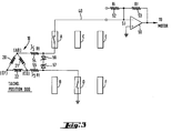
- sensitivity in this arrangement is limited by the voltage range of the transistor switches. Sensitivity of the system can be substantially improved in accordance with a preferred embodiment of this invention.as shown in Fig. 3 wherein the tachometer is operated in a current mode rather than a voltage mode. To achieve this, the resistance seen by the tachometer including the input resistance R t is split and placed in the lines between the windings and the switching bridge. Junction AB of the windings 20 and 21 is connected to switch A through one half of the input resistor 54, and junction CD of windings 22 and 21 is connected to switch D through the other half of the input resistor 55. A bipolar pair of Zener diodes 56 and 57 is connected between the lines connecting to switches A and D. Line 40 at the tachometer output is connected directly to summing junction SJ.
- a summing amplifier circuit such as that including amplifier 50
- the summing junction is at virtual ground. Therefore, when switches A and D are conductive, as shown, the entire path through the switches is at virtual ground.
- the signal developed by windings 20-22 appears as a current through resistors 54 and 55 which is then applied directly to summing junction SJ. Since the circuit through switches A and D remains at virtual ground when the switches are conductive, the operating voltage range of the transistors is not exceeded even at maximum output from the alternator 10. Thus, sensitivity can be substantially increased.
- Zener diodes 56 and 57 are selected having threshold values which limit the potential across the windings to the operating range of the transistors so that the operating ranges are not exceeded when the switches are in the non-conductive state.
- Fig. 4 is a schematic diagram of the complete system of the type shown in Fig. 3.
- the output of operational amplifier 50 is supplied to a drive amplifier 64 which, in turn, is connected to drive motor 65.
- Motor 65 and alternator 10 of the tachometer have a common shaft.
- Junction AB of the tachometer windings 20 and 21 is connected to switches A and B in bridge circuit 12 via resistor 54, whereas junction CD is connected to switches C and D via resistor 55 and junction EF is connected to switches E and F via 58.
- Zener diodes 56 and 57 and 60 to 63 are connected across the three pairs of lines between the windings and the switches to limit the winding output voltages when the respective switches are non-conductive.
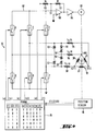
- Fig. 5 is a schematic diagram of another embodiment of the invention wherein the commutation is on a line-to-neutral basis rather than a line-to-line basis in order to reduce ripple content on the tachometer output signal.
- the alternator 100 includes windings 101-103 wound in a three-phase wye configuration.
- One end of winding 101 is connected to switches A and B of a switching bridge circuit 120 via a resistor 110
- one end of winding 102 is connected to switches C and D via resistor 111
- one end of winding 103 is connected to switches E and F via resistor 112.
- the other ends of windings 101-103 are connected to switches G and H.
- Switches A to H are FET's of the type previously described (Fig. 1).
- Switches B, D, F and H are connected to ground whereas switches A, C, E, and G are connected to a common tachometer output line 126.
- Resistors 110-112 are the input resistors of the summing circuit for developing the tachometer output current supplied to summing junction SJ via output line 126.
- a resistor 130 connected to the summing junctions receives the command signal.
- Resistor 131 provides negative feedback around operational amplifier 132.
- the summing junction is connected to the inverting input of amplifier 132 and the non-inverting input thereof is connected to ground.
- the output of amplifier 132 is supplied to a drive amplifier 133 which, in turn, controls energization of motor 134.
- Motor 134, alternator 100 and a position sensor 124 are coupled to a common shaft.
- the position sensor 124 provides a three digit code representative of six shaft positions,and the output code therefrom is supplied as the address to a 32x8 PROM 122.
- the table stored in PROM 122 is shown in Fig. 5.
- the outputs (a) to (h) are connected to control the conductive states of switches A to H, respectively.
- Fig. 5 operates similarly to the one of Fig. 4. It should be noted that in Fig. 5 the Zener diodes are not required to protect the FET switches in bridge circuit 120 since it is possible to connect the open winding across the unused one of resistors 110-112. For example, when the rotor is in position "000" (top line of table stored in PROM 122), switches A, D, E and G are conductive. As a result, current flows from ground through switch D, resistor 111, winding 102, winding 101, resistor 110 and switch A to summing junction SJ to thereby provide the tachometer output signal. Switches E and G connect resistor 112 across the remaining winding 103 to limit the generated potential to a low value within the operating range of transistors in switching bridge circuit 120.
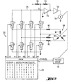
- Fig. 6 is a schematic diagram of still another embodiment of the invention wherein the winding is in a six phase grounded neutral configuration.
- the alternator 150 includes six windings 151 to 156 wound in a six phase common neutral configuration.
- the winding neutral is hard wired to ground.
- the free ends of windings 151 to 156 are connected to switches A to F on switch array 170 via series resistors 161 to 166, respectively.
- Switches A to F can be FET's of the type previously described or can be of a single chip configuration CD 4051B. Switches A to F are connected to a common tachometer output line 177.
- Resistors 161 to 166 are the respective input resistors of the summing junction circuit for developing the tachometer output current supplied to summing junction SJ via output line 177.
- a resistor 171 is connected to the summing junction and receives the command signal for the controlling servo system.
- the series combination of resistor 172 and capacitor 173 provides the feed back across operational amplifier 174.
- Summing junction SJ is connected to the inverting input of amplifier 174 and the noninverting input thereof is connected to ground.
- the output of amplifier 174 is connected to provide energization for the motor 175.
- Motor 175, alternator 150 and position sensor 176 are coupled to a common shaft.
- the position sensor 176 provides a three digit code representative of six shaft positions and this output code is supplied to a PROM 178 as the addressing code.
- the table stored in PROM 178 is shown in Fig. 6.
- the outputs (a) to (f) are connected to control the conductive states of switches A to F, respectively.
- Fig. 6 operates similar to the prior embodiments. In this case, however, for each commutation position only a single switch is required to complete the winding connection from ground to the tachometer output line 177. As a result, since fewer switches are required per winding connection, the switching spikes or transients are reduced with this arrangement. The fact that the winding neutral 157 is hard wired to ground further reduces noise in the tachometer output.
- Open circuit voltage protection is provided for the low voltage FET switches by means of clamping diodes 180.
- Resistors 161 to 166 are connected to a positive reference voltage +V via diodes 181 to 186, respectively, and are connected to a negative reference voltage -V via diodes 191 to 196, respectively.
- the clamping diodes 180 prevent the open circuit voltage across the windings from exceeding reference values + V and -V to thereby provide over voltage protection for the FET switches.
Landscapes
- Physics & Mathematics (AREA)
- General Physics & Mathematics (AREA)
- Control Of Motors That Do Not Use Commutators (AREA)
Applications Claiming Priority (4)
| Application Number | Priority Date | Filing Date | Title |
|---|---|---|---|
| US06/504,121 US4572999A (en) | 1983-06-14 | 1983-06-14 | Brushless tachometer |
| US56083883A | 1983-12-13 | 1983-12-13 | |
| US560838 | 1983-12-13 | ||
| US504121 | 1995-07-19 |
Publications (3)
| Publication Number | Publication Date |
|---|---|
| EP0128519A2 true EP0128519A2 (fr) | 1984-12-19 |
| EP0128519A3 EP0128519A3 (fr) | 1987-07-01 |
| EP0128519B1 EP0128519B1 (en) | 1991-11-21 |
Family
ID=27054733
Family Applications (1)
| Application Number | Title | Priority Date | Filing Date |
|---|---|---|---|
| EP84106449A Expired - Lifetime EP0128519B1 (en) | 1983-06-14 | 1984-06-06 | Brushless tachometer |
Country Status (2)
| Country | Link |
|---|---|
| EP (1) | EP0128519B1 (fr) |
| DE (1) | DE3485279D1 (fr) |
Cited By (2)
| Publication number | Priority date | Publication date | Assignee | Title |
|---|---|---|---|---|
| WO1995005606A1 (fr) * | 1993-08-16 | 1995-02-23 | Robert Bosch Gmbh | Circuit permettant de mesurer la vitesse de rotation d'un alternateur |
| FR2963177A1 (fr) * | 2010-07-22 | 2012-01-27 | Snecma | Controle d'une generatrice tachymetrique dans une turbomachine |
Family Cites Families (4)
| Publication number | Priority date | Publication date | Assignee | Title |
|---|---|---|---|---|
| GB913170A (en) * | 1959-10-09 | 1962-12-19 | Ferranti Ltd | Improvements relating to direct current tachometer generators |
| US4088943A (en) * | 1977-02-25 | 1978-05-09 | Electro-Craft Corporation | Brushless DC tachometer circuit |
| JPS5617887U (fr) * | 1979-07-19 | 1981-02-17 | ||
| CA1142345A (fr) * | 1979-08-31 | 1983-03-08 | Gerald L. Tumbush | Dispositif de mesure du type a reseau de diffraction a detection par photodiode |
-
1984
- 1984-06-06 EP EP84106449A patent/EP0128519B1/en not_active Expired - Lifetime
- 1984-06-06 DE DE8484106449T patent/DE3485279D1/de not_active Expired - Lifetime
Cited By (4)
| Publication number | Priority date | Publication date | Assignee | Title |
|---|---|---|---|---|
| WO1995005606A1 (fr) * | 1993-08-16 | 1995-02-23 | Robert Bosch Gmbh | Circuit permettant de mesurer la vitesse de rotation d'un alternateur |
| US5602470A (en) * | 1993-08-16 | 1997-02-11 | Robert Bosch Gmbh | Circuit arrangement for starting detection of three-phase generator |
| DE4327485B4 (de) * | 1993-08-16 | 2005-10-27 | Robert Bosch Gmbh | Schaltungsanordnung zur Messung der Drehzahl eines Generators |
| FR2963177A1 (fr) * | 2010-07-22 | 2012-01-27 | Snecma | Controle d'une generatrice tachymetrique dans une turbomachine |
Also Published As
| Publication number | Publication date |
|---|---|
| EP0128519A3 (fr) | 1987-07-01 |
| EP0128519B1 (en) | 1991-11-21 |
| DE3485279D1 (de) | 1992-01-02 |
Similar Documents
| Publication | Publication Date | Title |
|---|---|---|
| US4565956A (en) | Fast-acting servo drive system | |
| EP0073503B1 (fr) | Système de commande pour moteurs synchrones sans balais | |
| US4364005A (en) | Brushless tachometer generator | |
| EP0128518B1 (fr) | Tachymètre à courant continu sans balais | |
| CA1222298A (fr) | Servo-moteur a grande resolution commute par reactance | |
| US4392094A (en) | Brushless D-C motor | |
| US4484115A (en) | Brushless motor | |
| US3329852A (en) | Direct-current motor with permanentmagnet rotor and sequentially energized stator windings | |
| US5552682A (en) | Device for detecting rotational position of brushless motor | |
| US4230976A (en) | Brushless, permanent magnet d-c motor with improved commutation control | |
| US4884016A (en) | Closed loop torque angle control of synchronous motor | |
| US4283664A (en) | Control signal generator for the commutating device of a brushless electronics motor | |
| US6313601B1 (en) | Speed control of a motor | |
| US4088943A (en) | Brushless DC tachometer circuit | |
| US4532461A (en) | Rotor position sensor error detection | |
| US4659953A (en) | Magnetic structure for synchro and tachometer | |
| US4066935A (en) | Stator winding control circuit for a brushless d.c. motor | |
| US4572999A (en) | Brushless tachometer | |
| GB2049322A (en) | Direct current motors | |
| US5334921A (en) | Circuit arrangement for operating a multi-phase synchronous motor in a direct voltage network | |
| US3250971A (en) | Direct-current motor with commutator | |
| EP0128519A2 (fr) | Générateur tachymétrique sans balais | |
| JPH0724455B2 (ja) | 励振コイルに対する電子的整流用回路装置 | |
| US4463299A (en) | Capacitive sensor motor control system | |
| JPS648555B2 (fr) |
Legal Events
| Date | Code | Title | Description |
|---|---|---|---|
| PUAI | Public reference made under article 153(3) epc to a published international application that has entered the european phase |
Free format text: ORIGINAL CODE: 0009012 |
|
| AK | Designated contracting states |
Designated state(s): CH DE FR GB IT LI SE |
|
| 17P | Request for examination filed |
Effective date: 19850419 |
|
| PUAL | Search report despatched |
Free format text: ORIGINAL CODE: 0009013 |
|
| AK | Designated contracting states |
Kind code of ref document: A3 Designated state(s): CH DE FR GB IT LI SE |
|
| 17Q | First examination report despatched |
Effective date: 19890718 |
|
| RAP1 | Party data changed (applicant data changed or rights of an application transferred) |
Owner name: KOLLMORGEN CORPORATION |
|
| GRAA | (expected) grant |
Free format text: ORIGINAL CODE: 0009210 |
|
| AK | Designated contracting states |
Kind code of ref document: B1 Designated state(s): CH DE FR GB IT LI SE |
|
| PUAB | Information related to the publication of an a document modified or deleted |
Free format text: ORIGINAL CODE: 0009199EPPU |
|
| PUAC | Information related to the publication of a b1 document modified or deleted |
Free format text: ORIGINAL CODE: 0009299EPPU |
|
| STAA | Information on the status of an ep patent application or granted ep patent |
Free format text: STATUS: THE APPLICATION HAS BEEN WITHDRAWN |
|
| REF | Corresponds to: |
Ref document number: 3485279 Country of ref document: DE Date of ref document: 19920102 |
|
| DB1 | Publication of patent cancelled | ||
| RA1 | Application published (corrected) |
Date of ref document: 19841219 Kind code of ref document: A2 |
|
| 18W | Application withdrawn |
Withdrawal date: 19911116 |
|
| R18W | Application withdrawn (corrected) |
Effective date: 19911116 |
|
| RIN1 | Information on inventor provided before grant (corrected) |
Inventor name: COULON, PHILIP SERGE |